At some points, to create certain designs, you may need certain tools or machines. For example, to give a pipe or profile a certain shape, i.e. there is a need for a change in shape. For such an action, a machine is needed that will help to cope with this work.
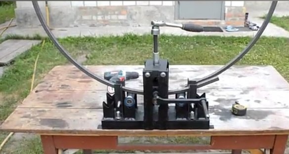
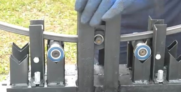
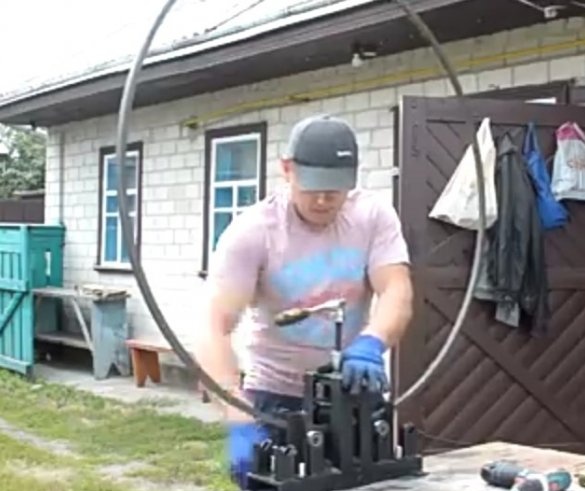
So the author of the YouTube channel Yuri Serbin had such a need. Therefore, for his needs, he assembled a machine that bends profile pipes. The design of this profile bending machine is quite simple to manufacture, the difficulty can only be caused by the need to find a turner in order to grind some details. If you have a lathe or a lathe at your disposal, then there should be no problems in the manufacture.
The tool that the wizard used when working:
-Welding machine,
-USHM (Bulgarian),
-drill,
- magnetic holders.
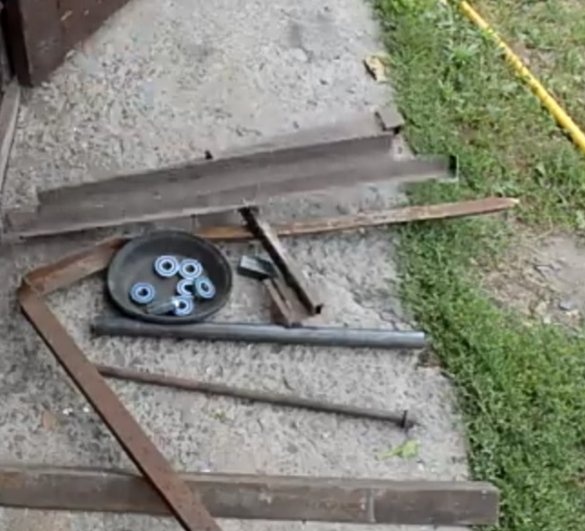
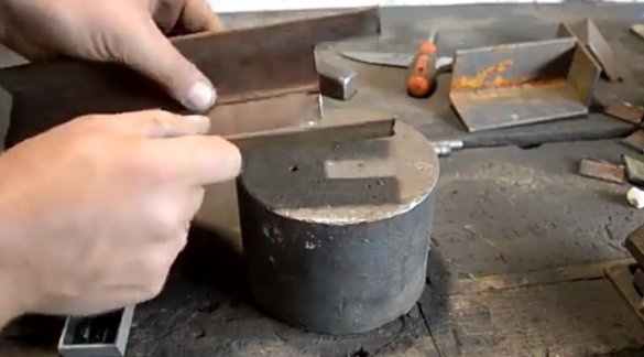
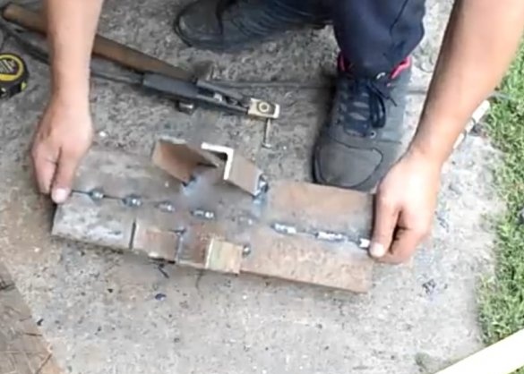
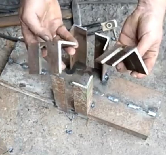
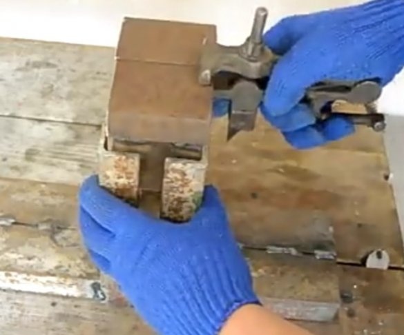
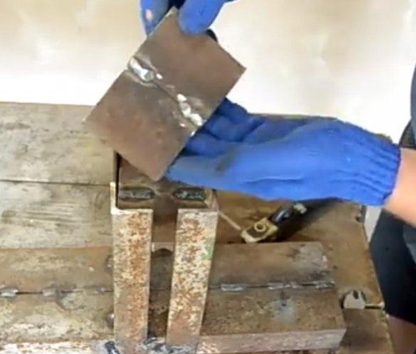
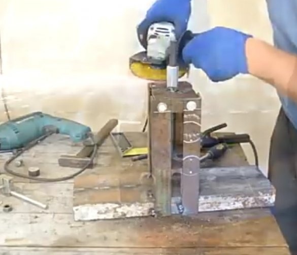
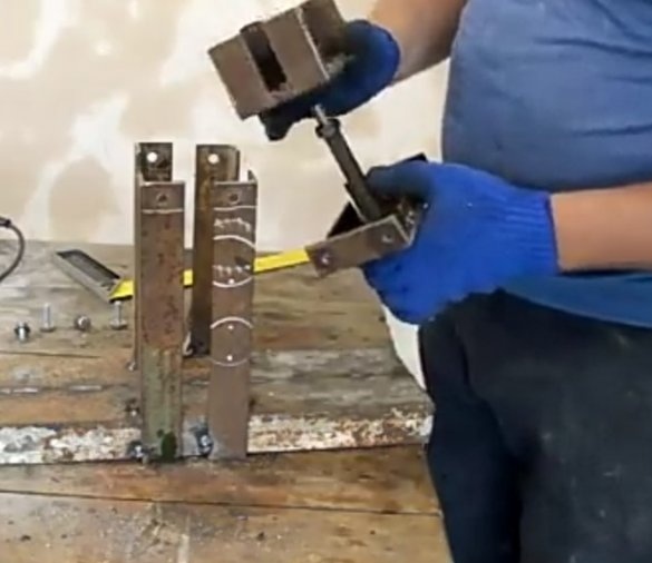
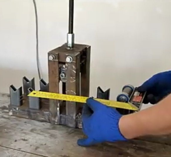
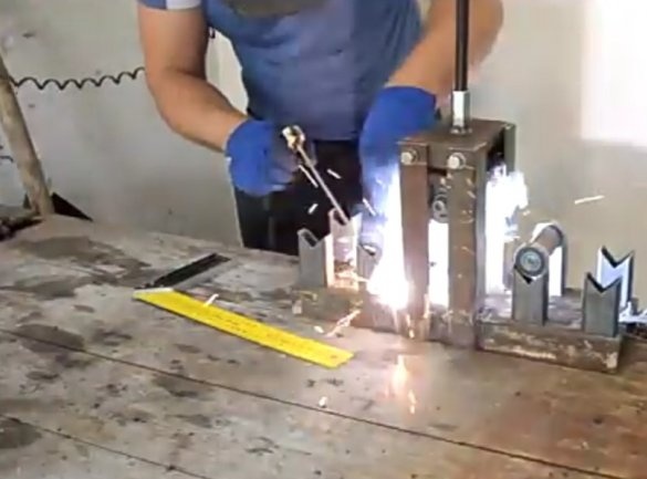
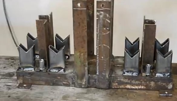
The author took most of the material needed for the manufacture of the machine in his the garage. Old corners and other pieces of iron were used. To begin with, the author makes the foundation of the future profile bending machine. To do this, he takes two corners of 60x40 mm and welds them together. Next, from a corner of size 35x35, workpieces under the rack for the middle roller are sawn off, which will bend the bent part. On one side of each corner, one wall is sawn so that it fits snugly to the base when welding. These parts are set on the base, checked for evenness by a corner and welded.
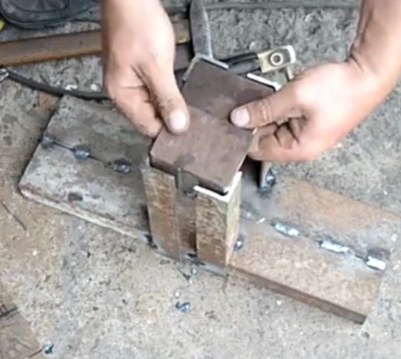
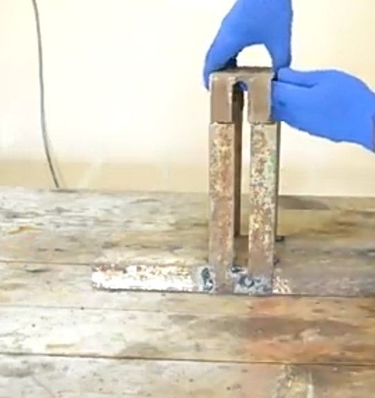
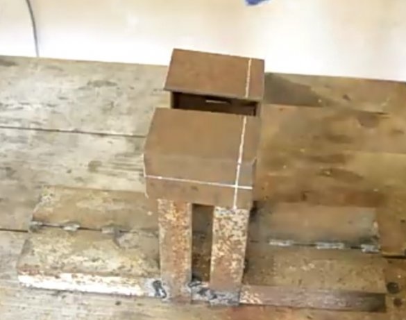
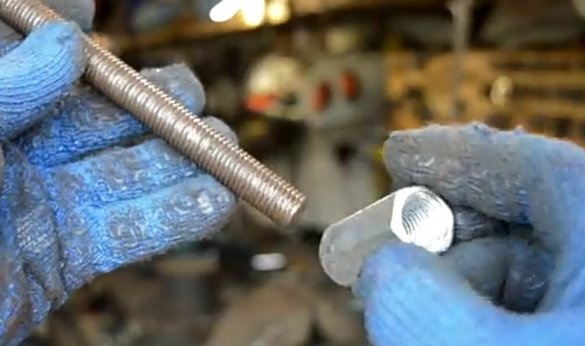
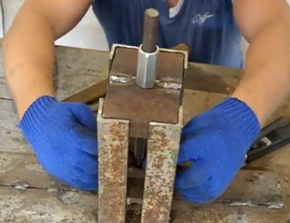
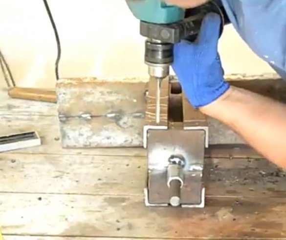
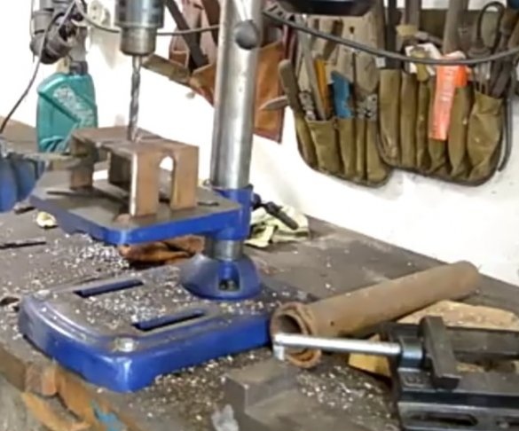
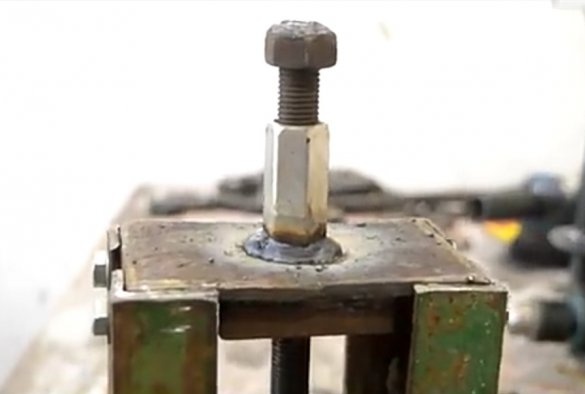
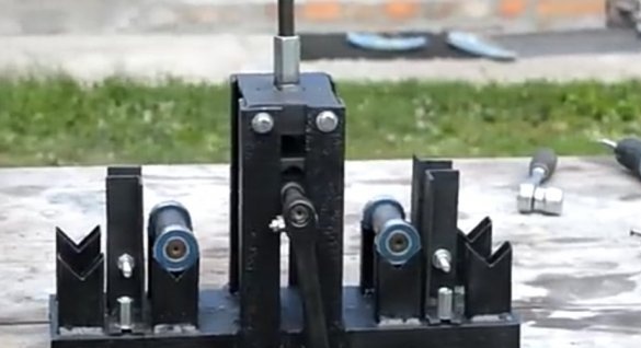
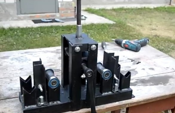
The next step is to make a platform for the twisting roller. Two corners 60x60 in size went on it, in the walls of which slots were made, which coincided with the distances between the racks of the middle roller. These parts are welded. Then, also from the corners, fitting them to the internal size of the support posts, a cover is created, in the middle of which a hole is drilled for the threaded rod. A high nut is welded onto it. Then the part is inserted into the racks so that its edges are flush with the edges of the support corners. Holes are drilled in which the thread is cut.Using a bolted connection, the parts are connected.
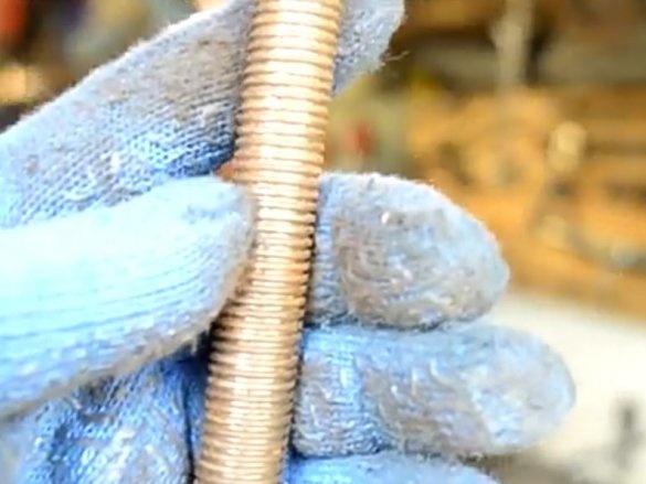
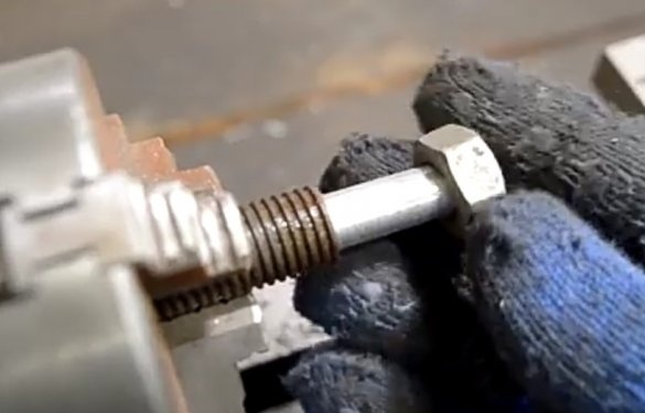
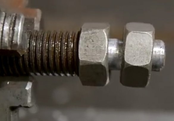
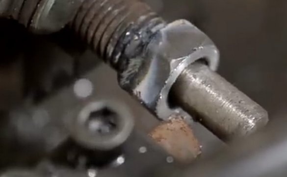
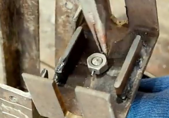
A thread is threaded at the lower end of the pin. A nut is put on this end and welded. A through hole is made in the second nut and end of the stud. A hole for the pin is made in the part on which the roller will be mounted. It is inserted into it, and at the end where there is a hole, a nut is inserted. A lock is passed through the holes so that it does not fly off. With this connection, the pin will spin and raise-lower the machine clamping mechanism.
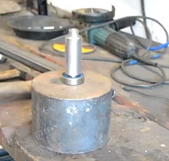
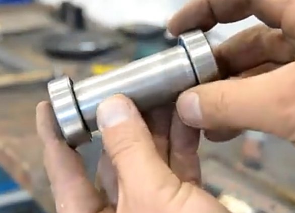
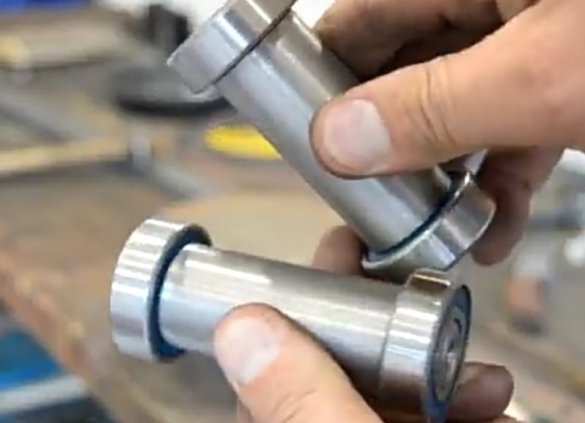
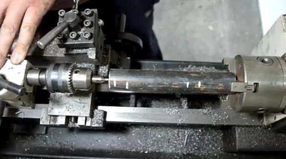
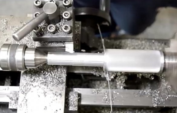
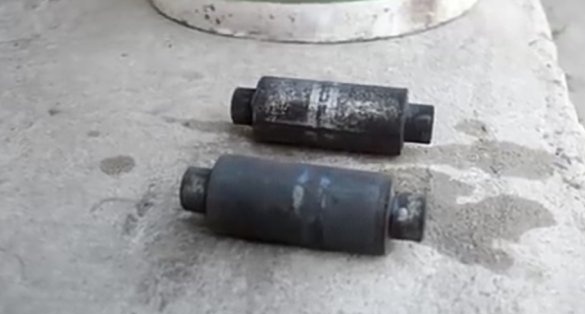
A metal rod is taken and the blanks on which the bearings will be mounted are cut off.
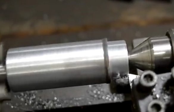
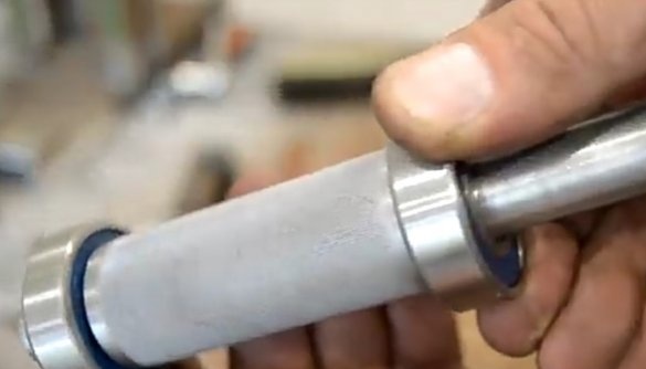
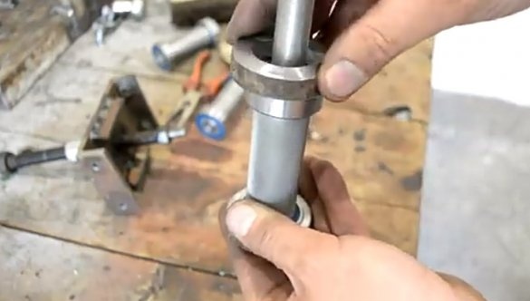
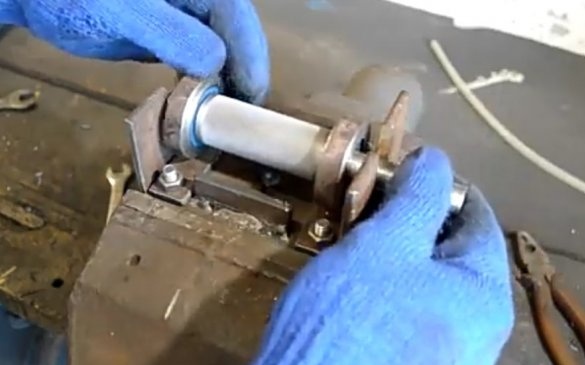
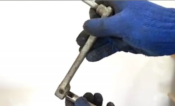
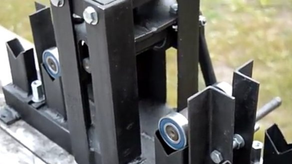
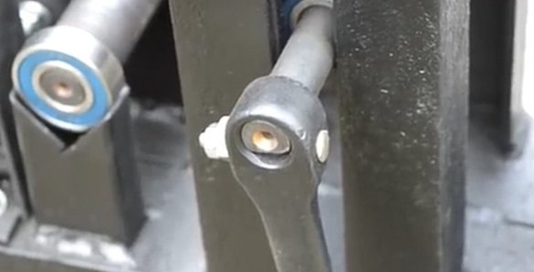
Further, with the help of a lathe, the author grinds the ends of the rollers so that the bearings are worn on them. That roller, which will be installed in the middle part of the machine, has a more elongated ground part. This is necessary so that a handle can be put on it that will power the machine. For bearings installed in the same part of the machine, the author grinds protective covers that are welded to the clamping part of the part.
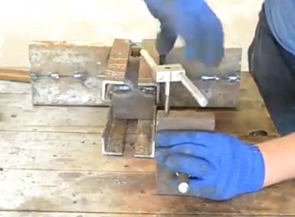
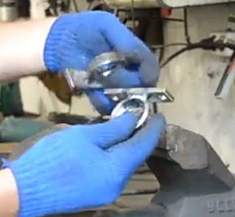
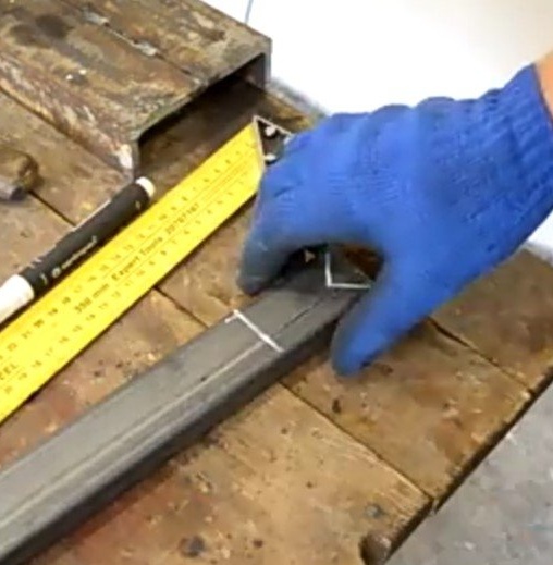
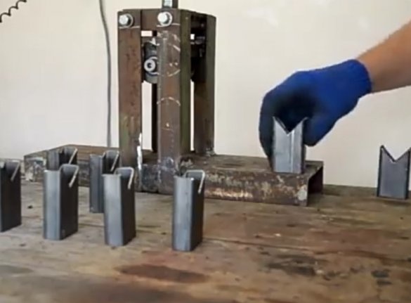
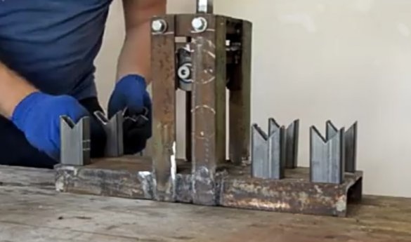
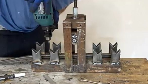
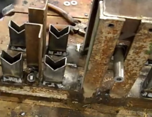
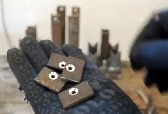
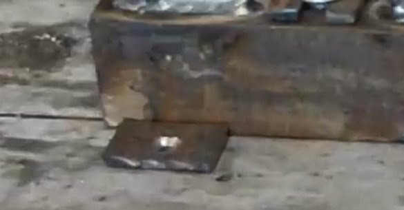
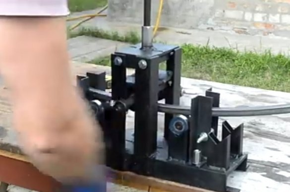
Supports are cut out of the 20x40 profile pipe, but the rollers with bearings will be installed. Sections similar to the structure of a dovetail are made in profiles. Such parts need 8 pieces. They are welded to the base, 4 pieces on each side. Rollers will be installed on them, along which the bent workpiece will ride. Between these supports are installed guides made of a corner. They will not be welded to the base, but mounted on it with bolts in order to be able to adjust the width depending on the bent profile. The next step is to install the handle and mounting plates. Plates are necessary for rigid attachment of the machine to the surface so that it is stable during operation.
The last step is painting and testing performance.
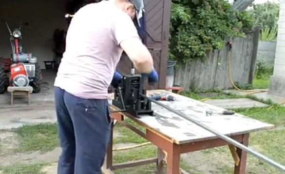
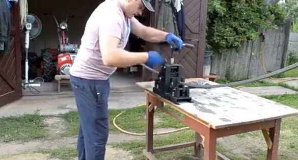
As you can see, the machine confidently copes with its task.

