More recently, 3D printers cost a lot of money and they were produced industrially. Accordingly, printed parts were expensive. Over time, enthusiastic friends began to assemble these devices themselves. A lot of instructions for assembling a 3D printer appeared on the network, and there are a lot of components on sale at affordable prices.
In this article, the Wizard presents its version of the 3D printer assembly. The master purchased most of the components for assembling the device on aliexpress.
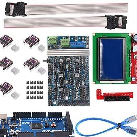
Tools and materials:
-A set of electronics for a 3D printer;
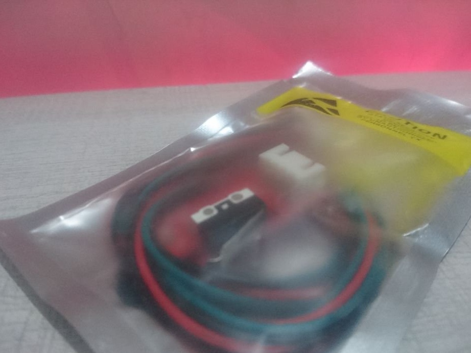
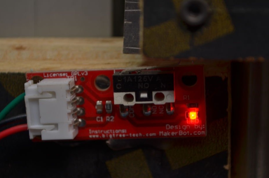
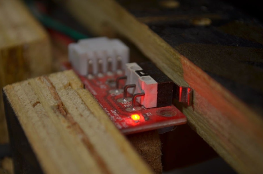
- Limit switch;
-Heating table;
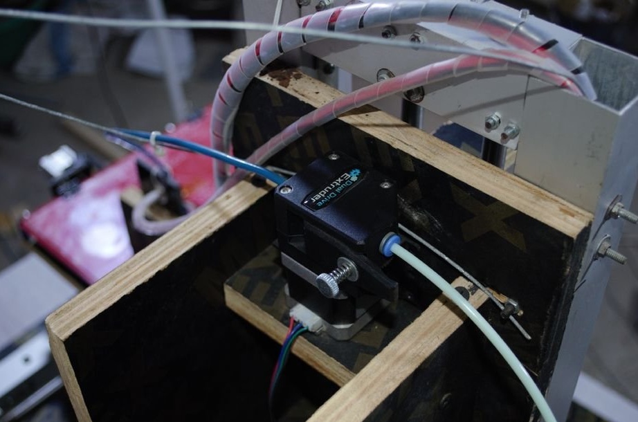
-Extruder;
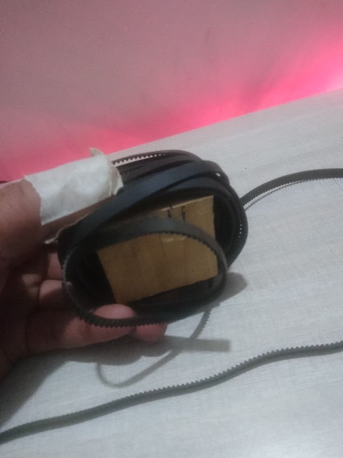
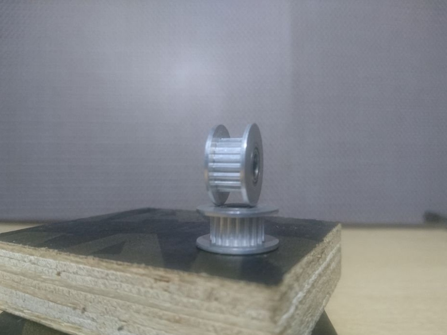
-Belt with pulleys;
-Tension roller;
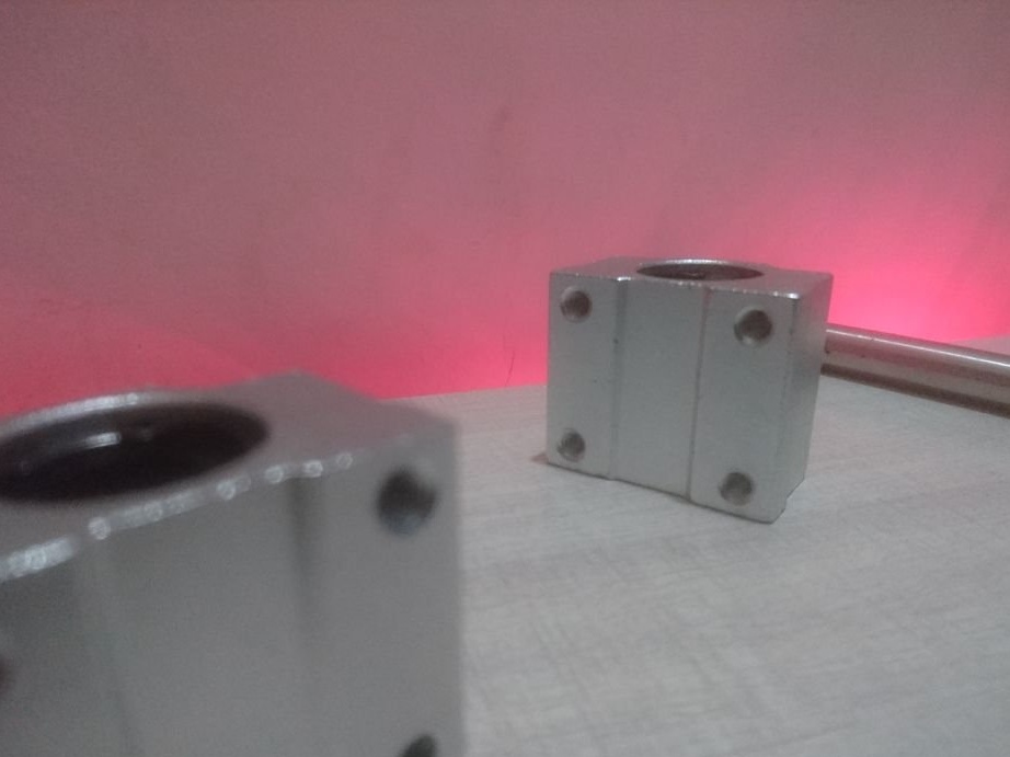
- Linear ball bearing;
-Spring for a warm table;
-Step engine 17HS4401;
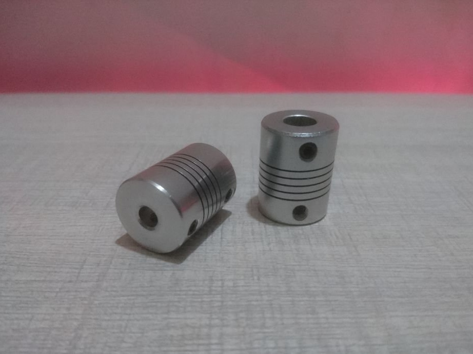
-Coupling;
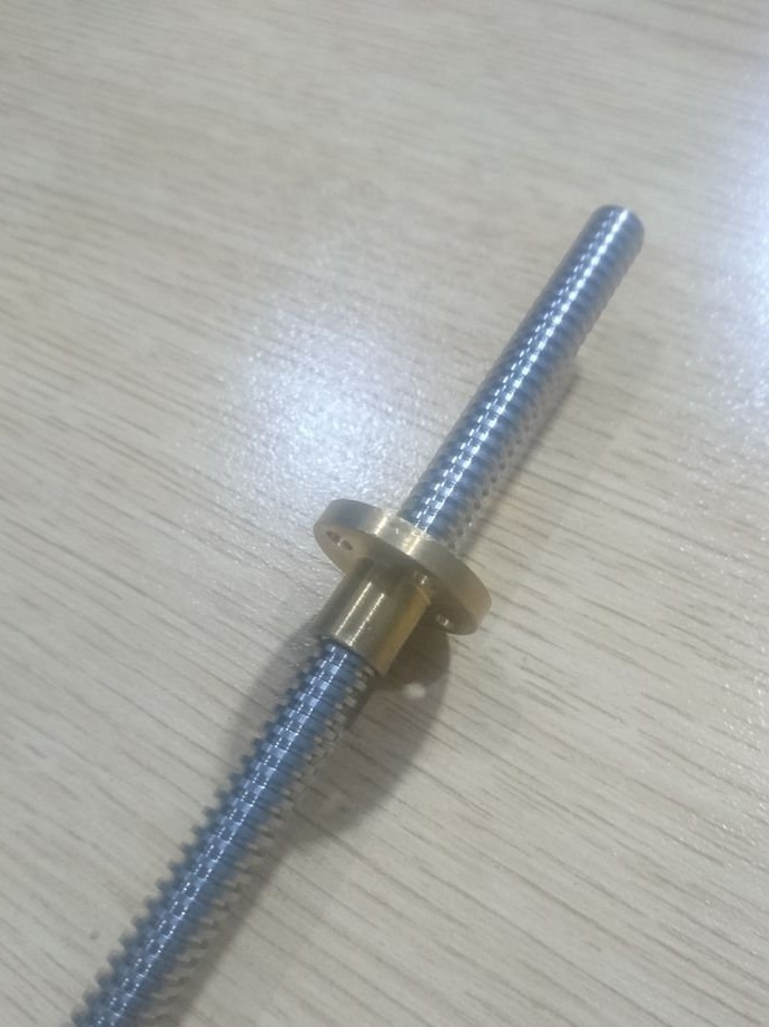
-Threaded stud;
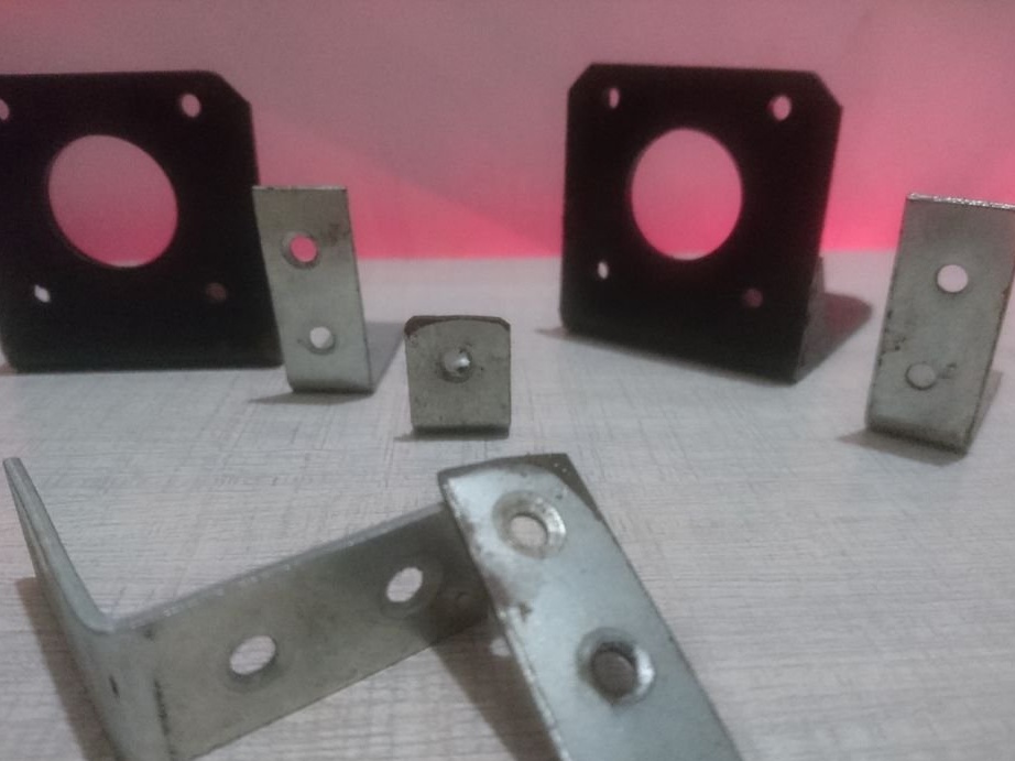
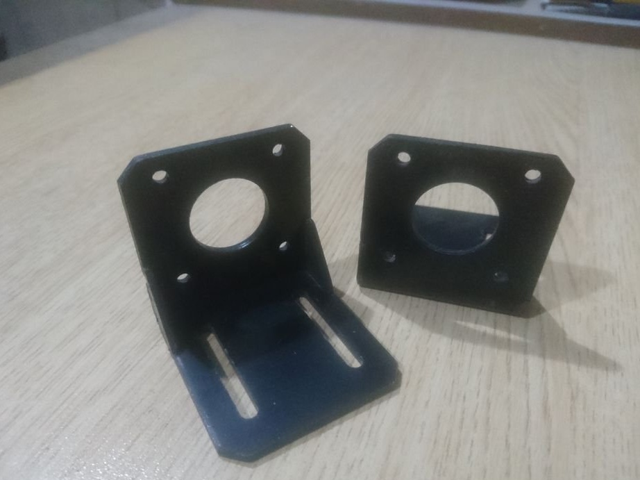
-Bracket;
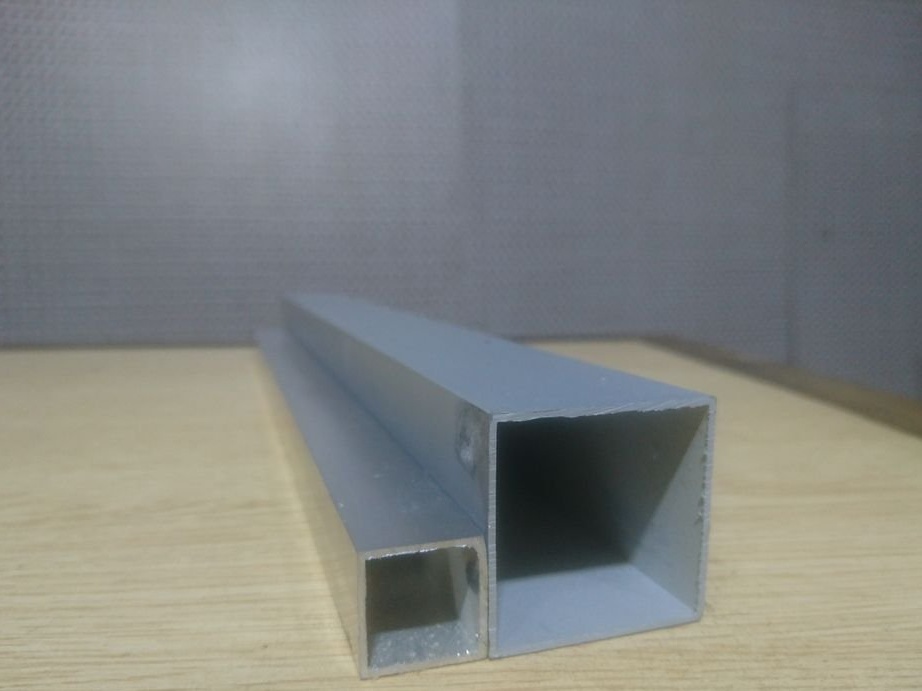
- Aluminum profile 39x39 mm;
- Aluminum profile 19x19 mm;
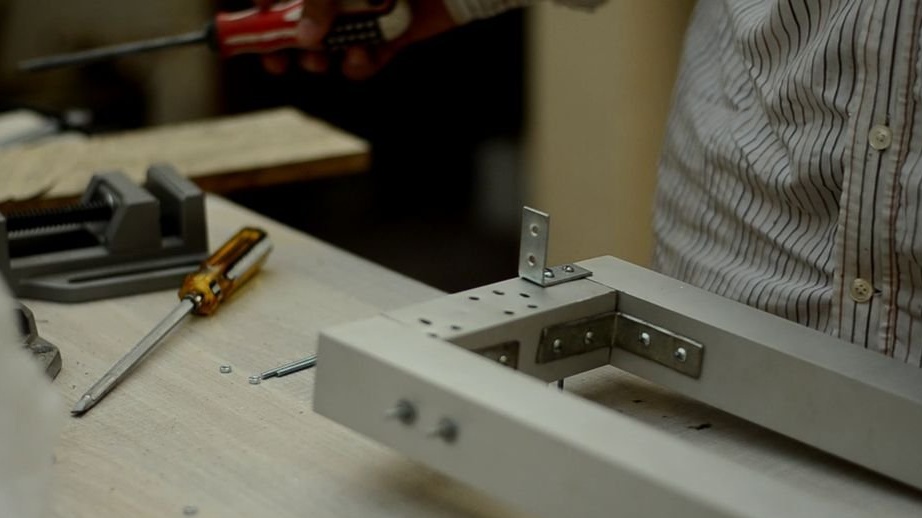
- Bracket 39x39x13mm 36pcs;
-Waterproof plywood 19 mm thick;
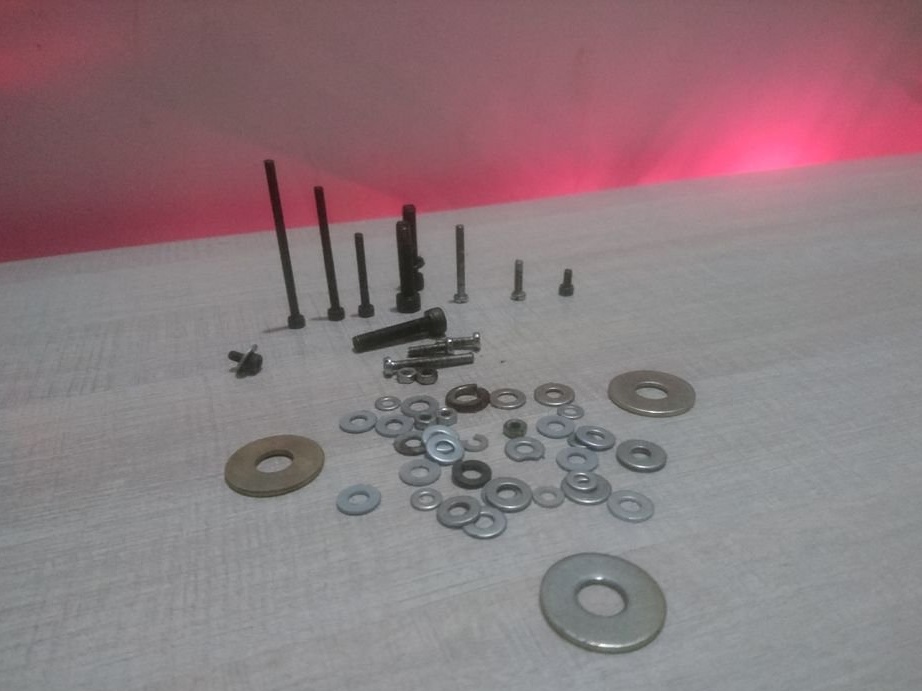
-Fasteners;

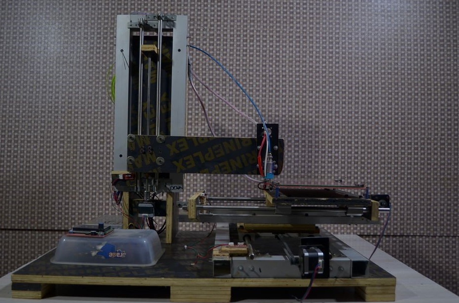
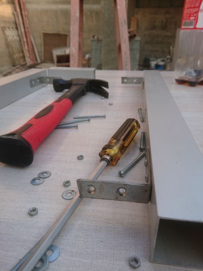
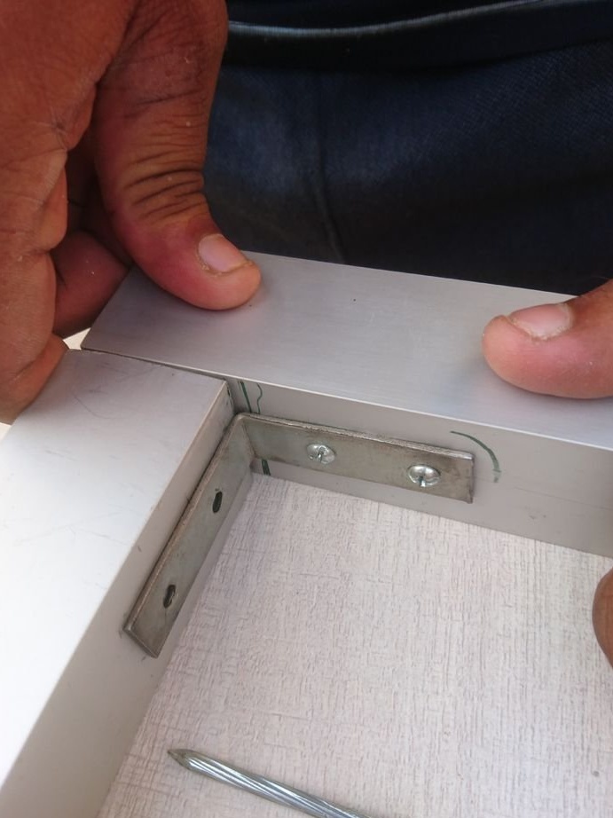
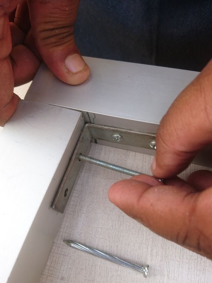
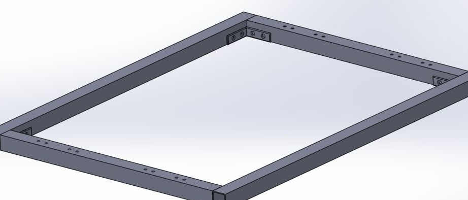
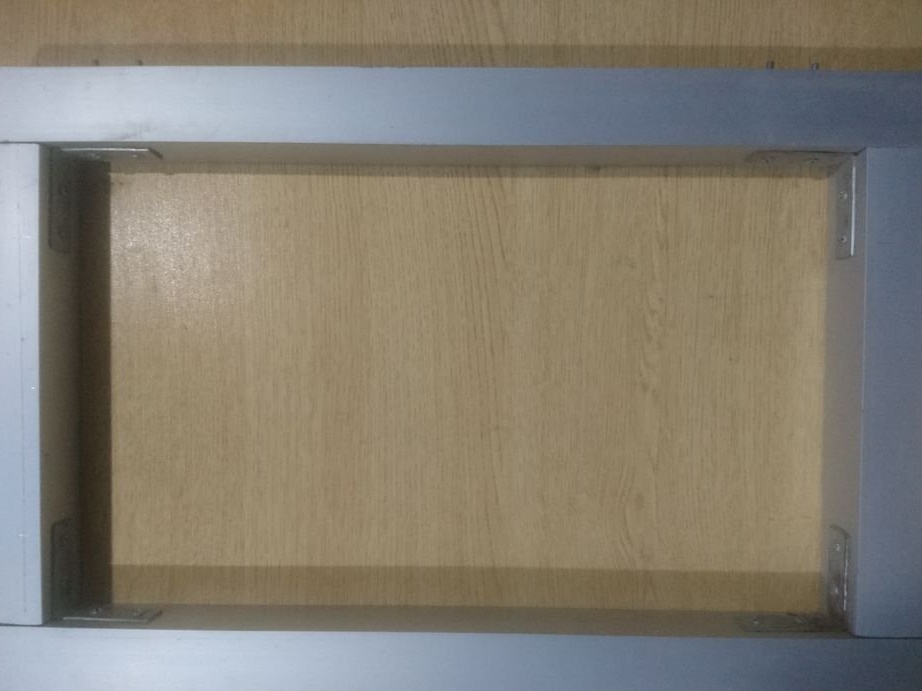
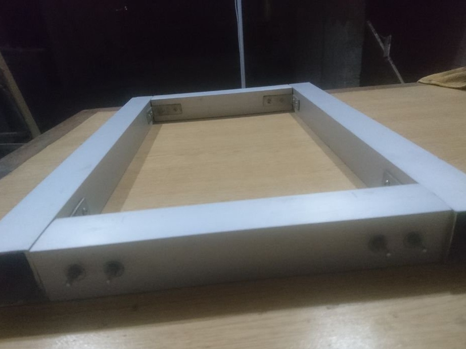
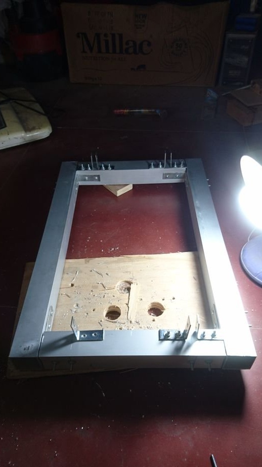
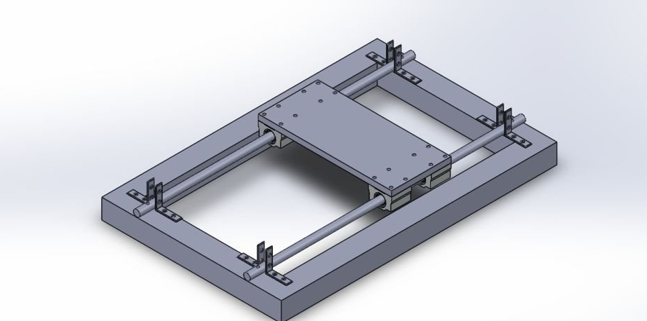
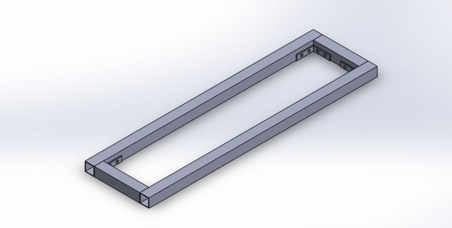
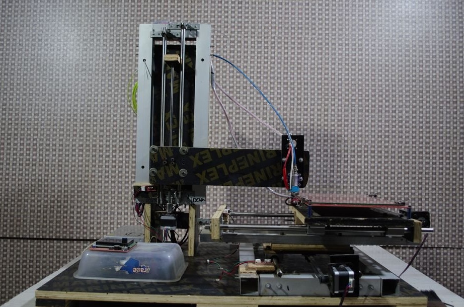
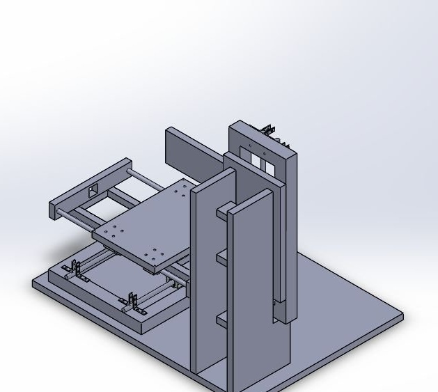
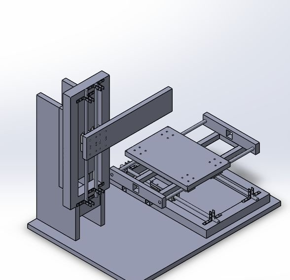
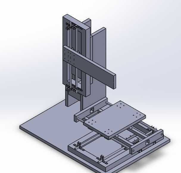
Step One: Frame
The x, y and z axes are built around the frame from aluminum shaped tubes. Axis travel will be
X> 300 mm
Y> 200 mm
Z> 250 mm (can be increased if necessary).
Based on this, the frame will be 420 mm (X, Z) x 460 mm (Y).
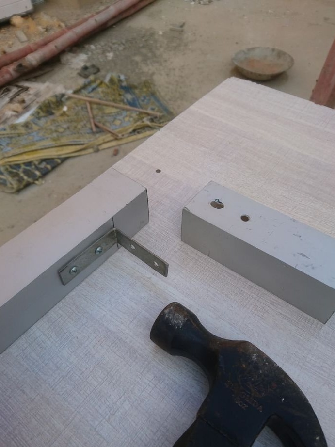
The wizard cuts the profile, and collects the frame.
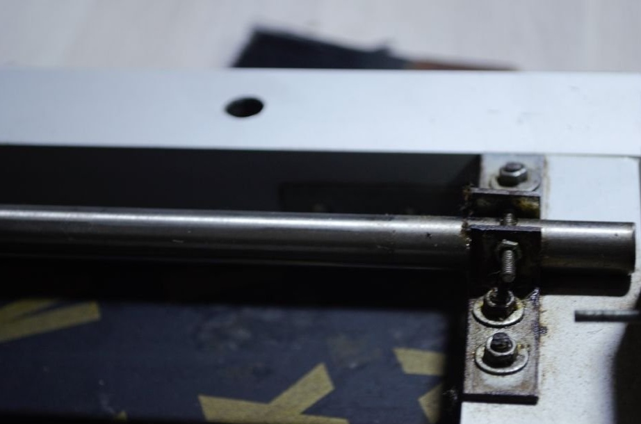
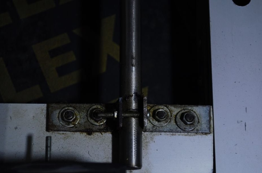
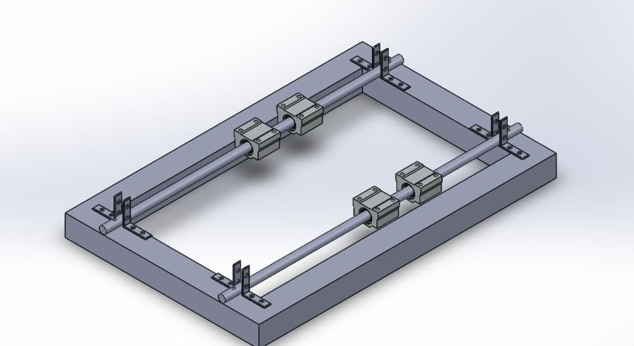
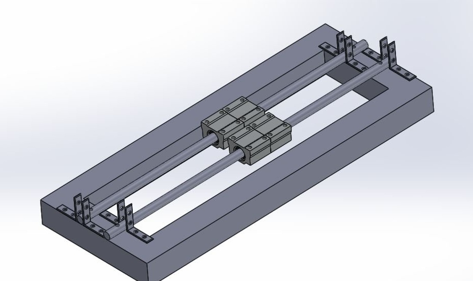
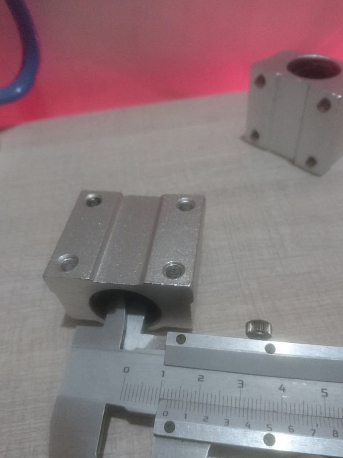
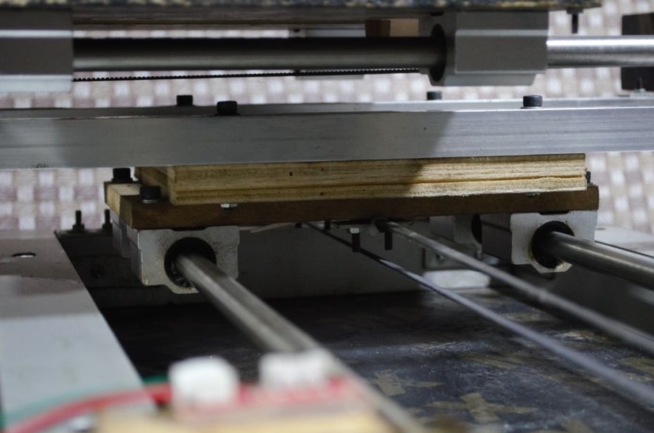
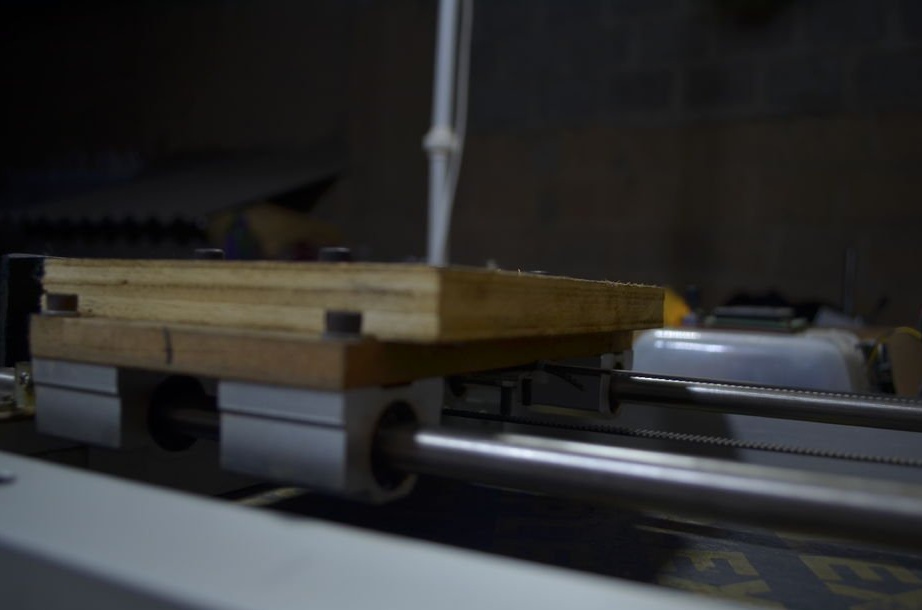
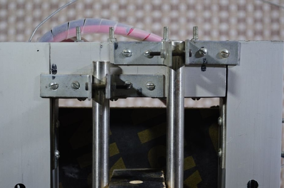
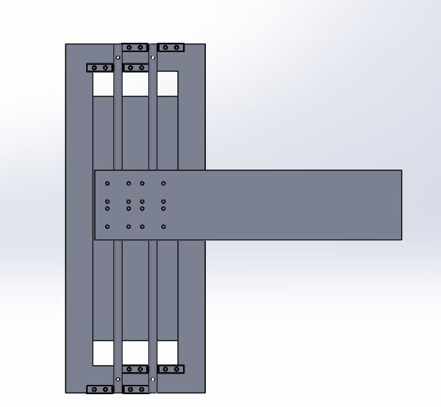
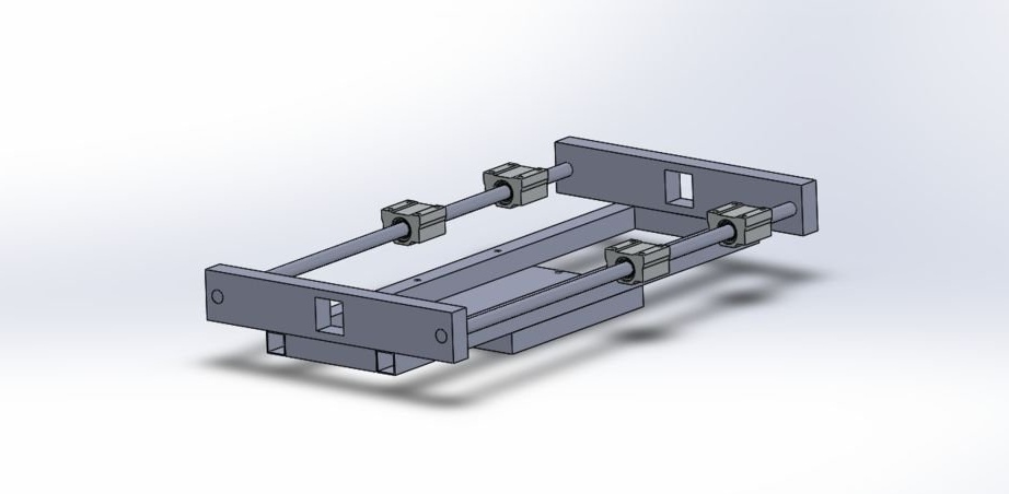
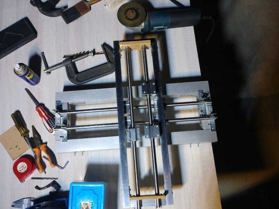
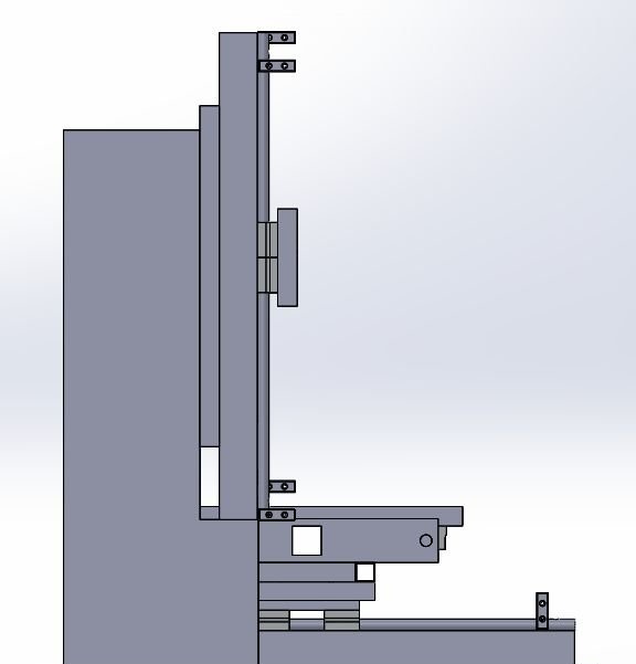
Step Two: Guide for X and Z Axis
For the X axis, 12 mm shafts with SC12UU linear bearing are used.
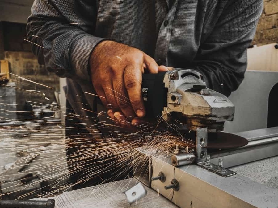
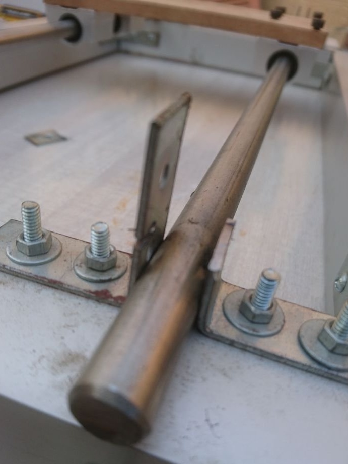
Two 12 mm rods are mounted on the frame using 8 corner brackets.
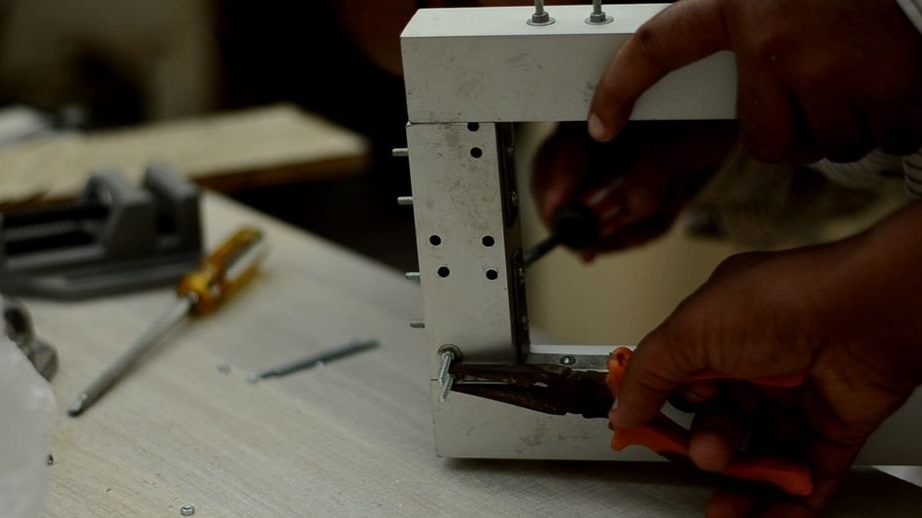
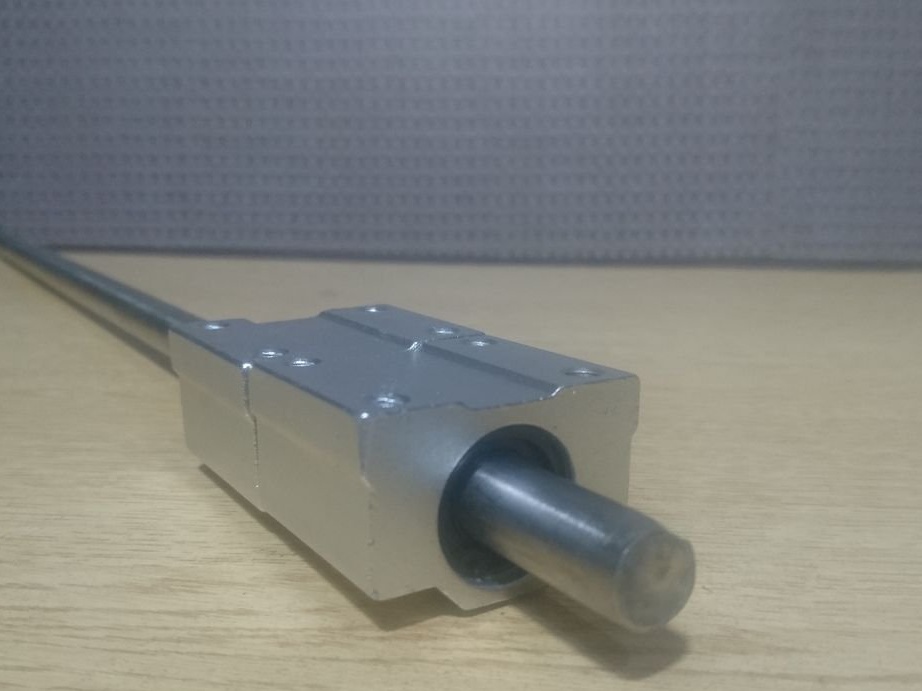
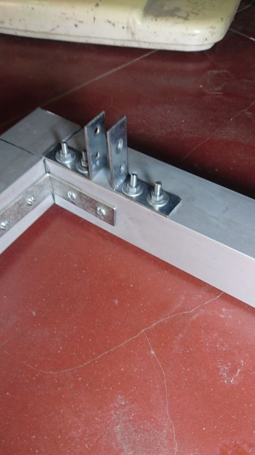
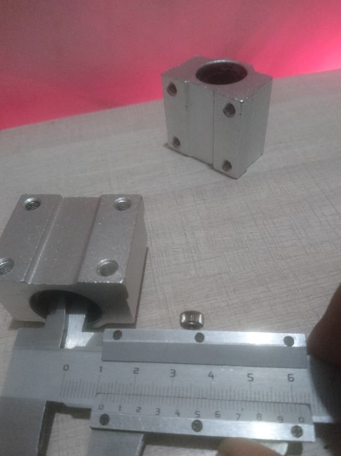
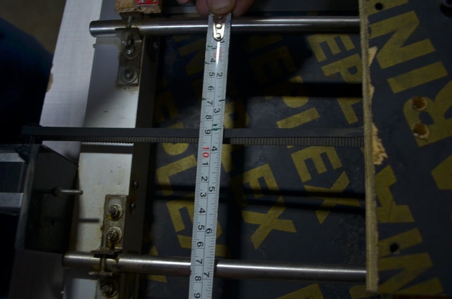
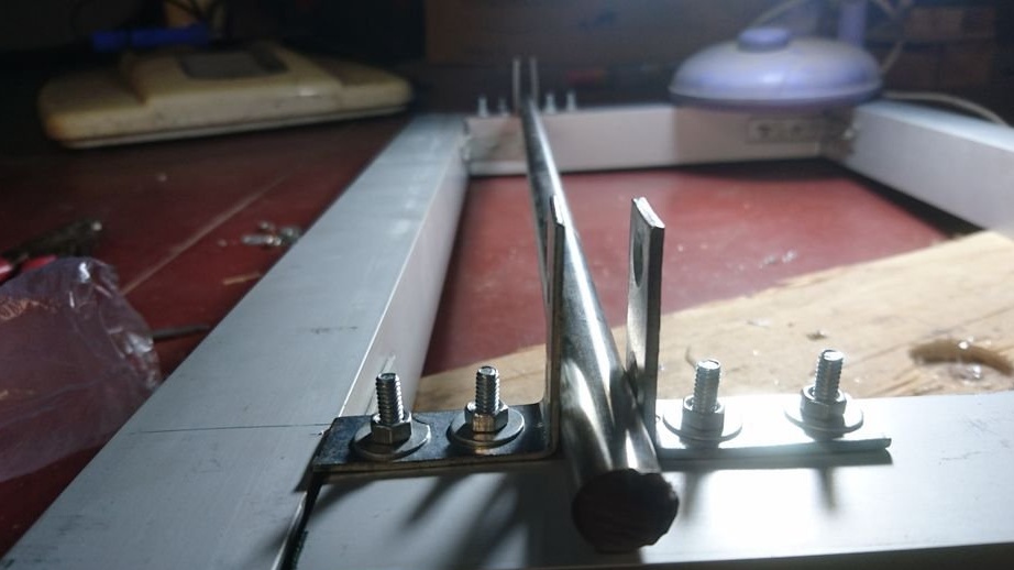
The excess part of the corner is cut off.
For the Z axis, only the frame size is changed, which is 500x200 mm.

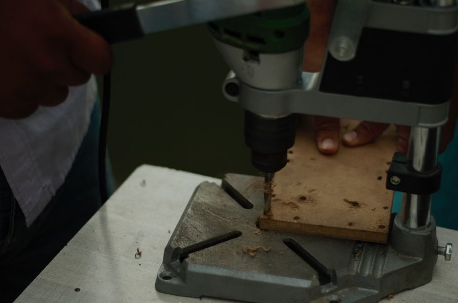
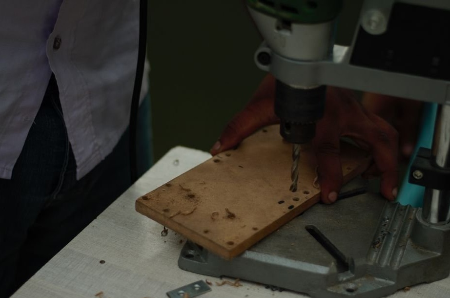
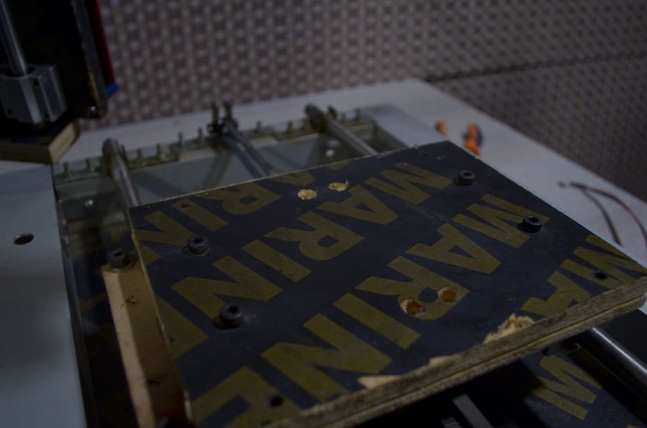
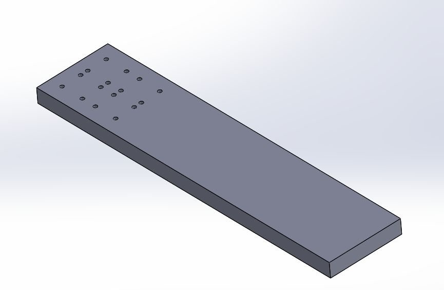
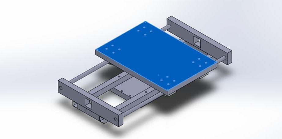
Step Three: X-axis table
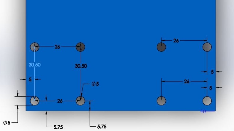
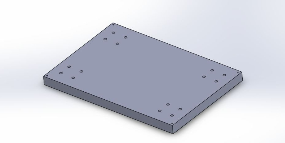
To make a table for the X axis, the master used a 10 mm thick MDF sheet. Cut MDF 210x110 mm. Drill mounting holes.
Sets guides.
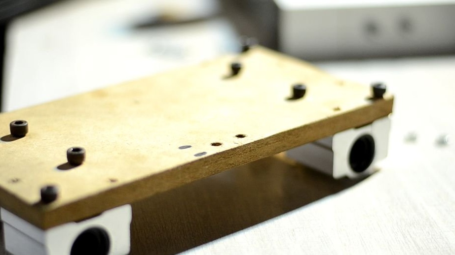
Sets the belt.
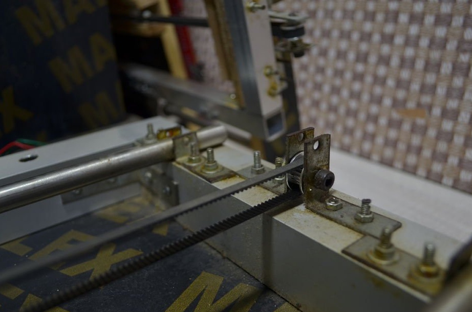
Installs the engine.

Sketches with hole sizes.
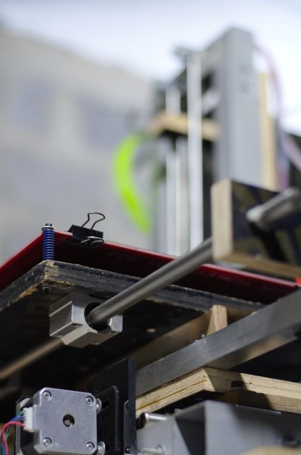
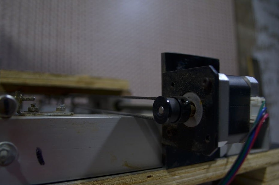
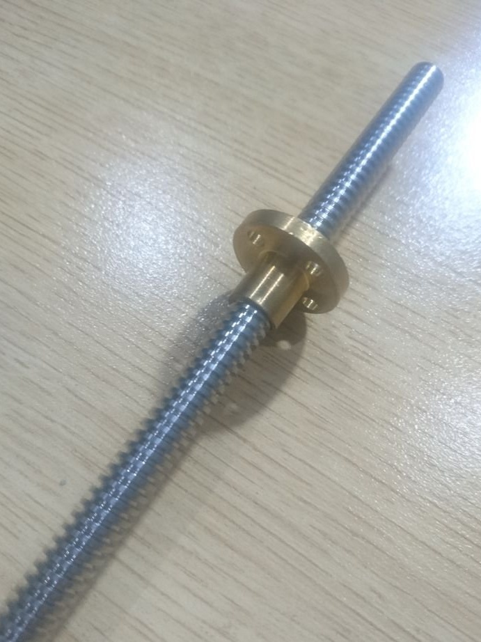
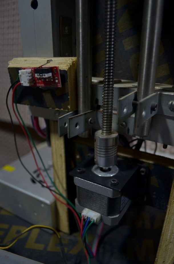
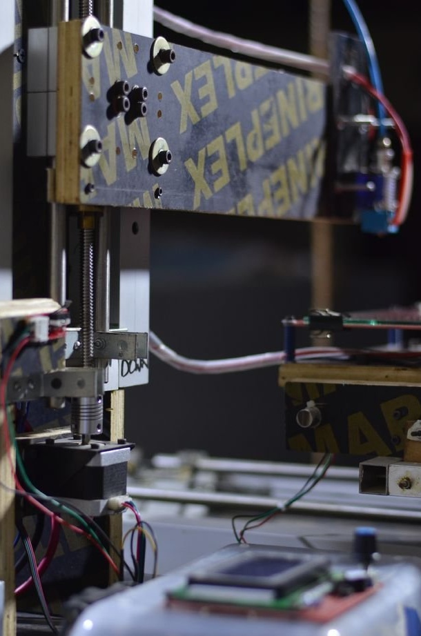
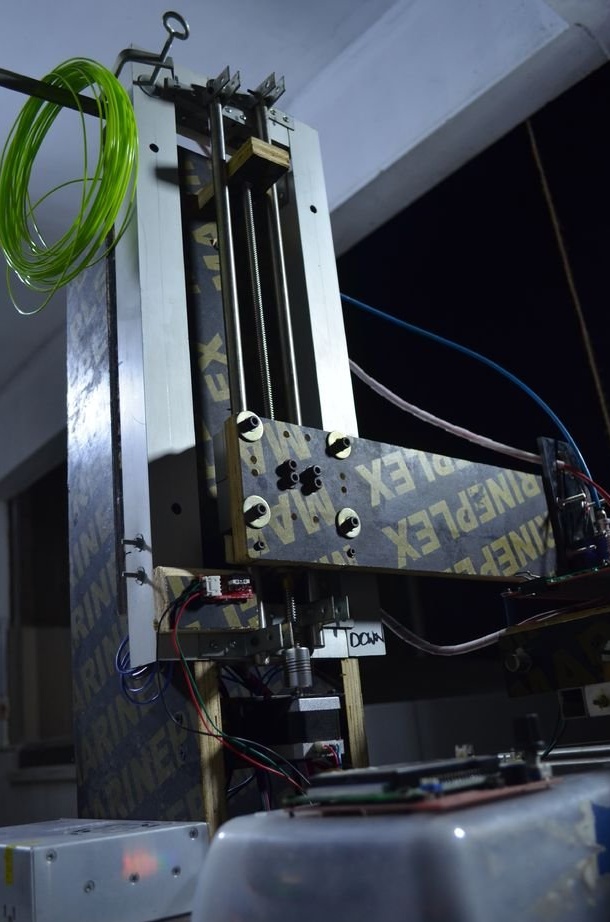
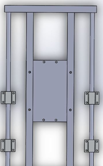
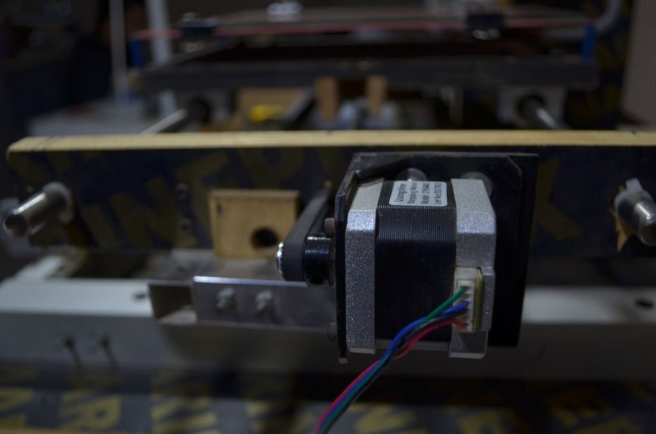
Step Four: Z Axis
The Z axis frame is attached to a rack of 19 mm plywood.
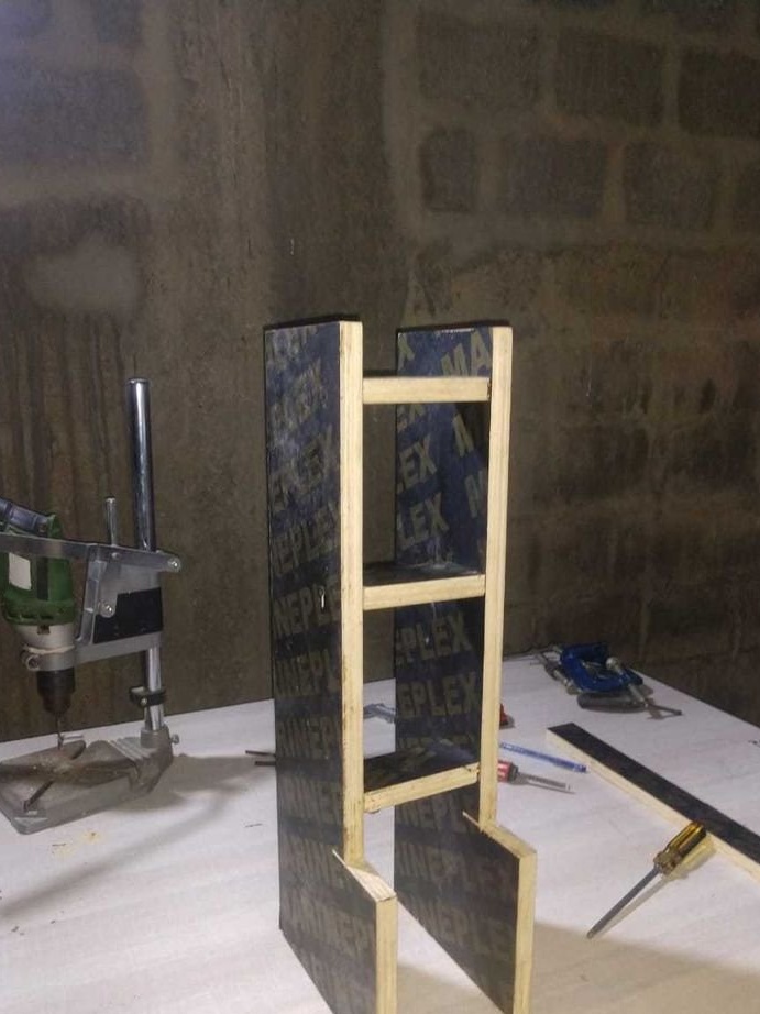
Attaches a frame to the rack.
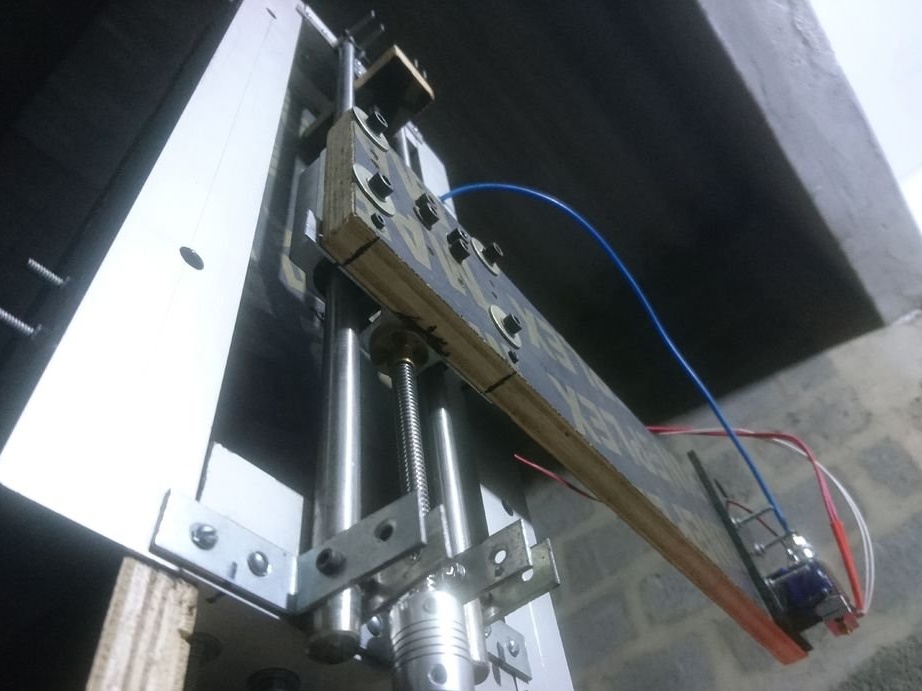
Installs propeller and motors.
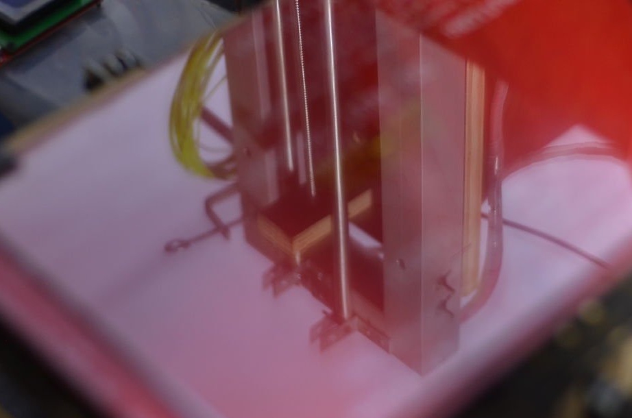
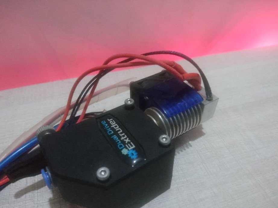
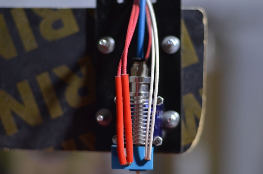
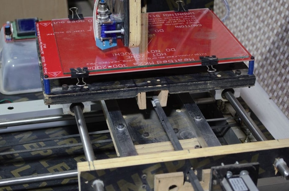
Step Five: Extruder
To install the extruder, the master cut a spacer from the PCB.

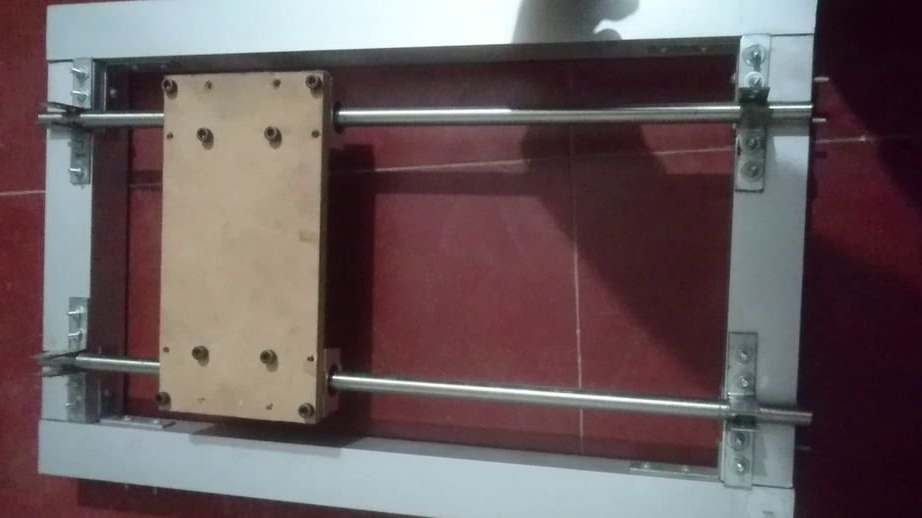
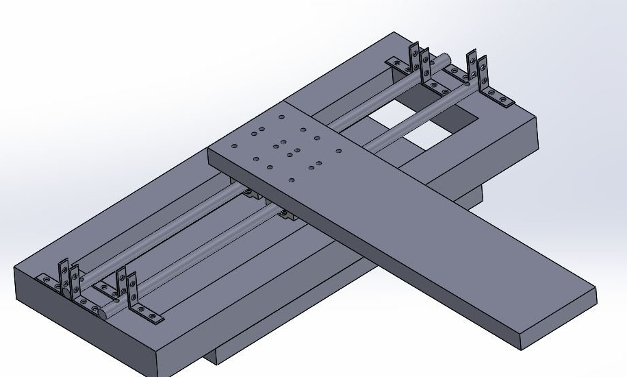
Step Five: Y-axis Guide
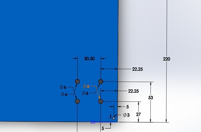
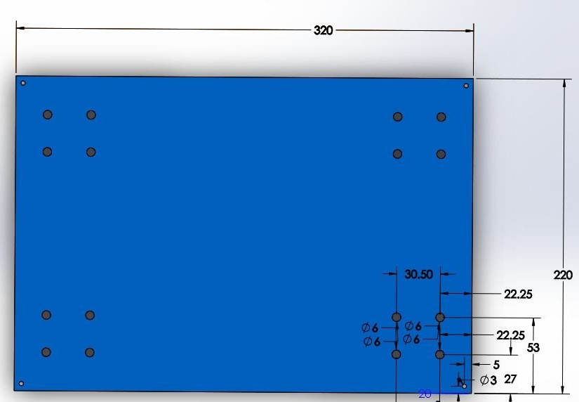
For the linear guide along the Y axis, the master used two parts from plywood. On these two parts along the center line, he drilled two 12 mm holes at a distance of 116.5 mm from the center for cylindrical rods. Now these plywood products can be easily fixed to the frame using 2 corner brackets and screws. The master also drilled a 15 mm hole in the center of these belt parts.

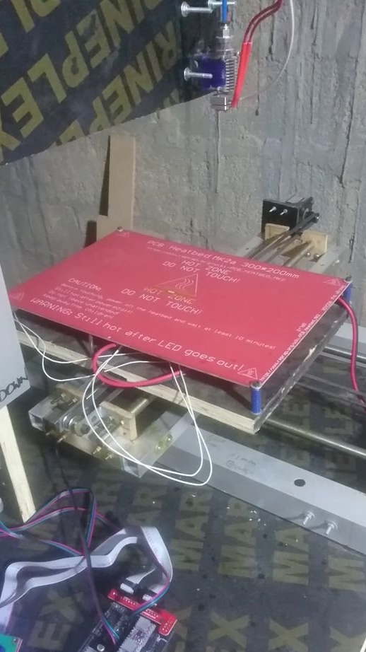
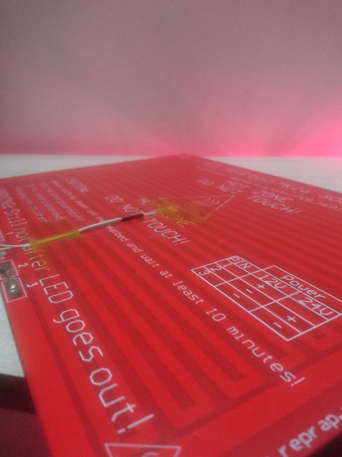
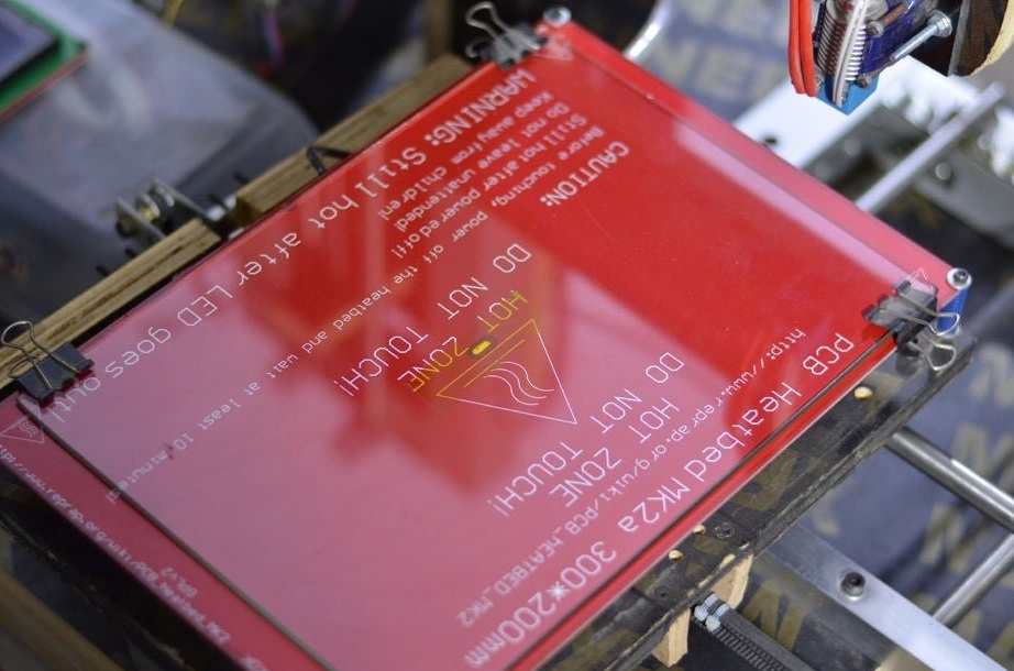
Step Six: a heating table
Next, the master sets the heating table.

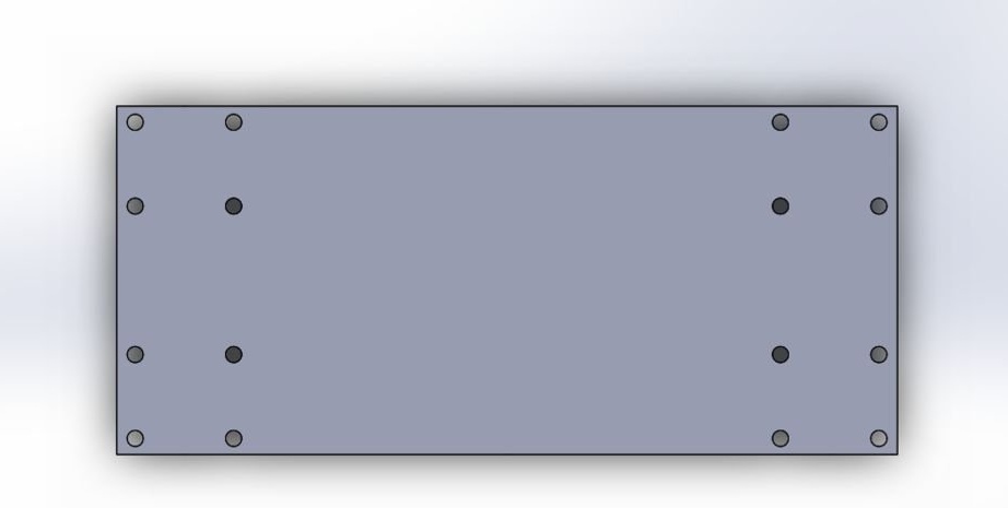
Seventh step: base
The basis for the machine is a plywood sheet.The master fixes a frame and a rack on it.
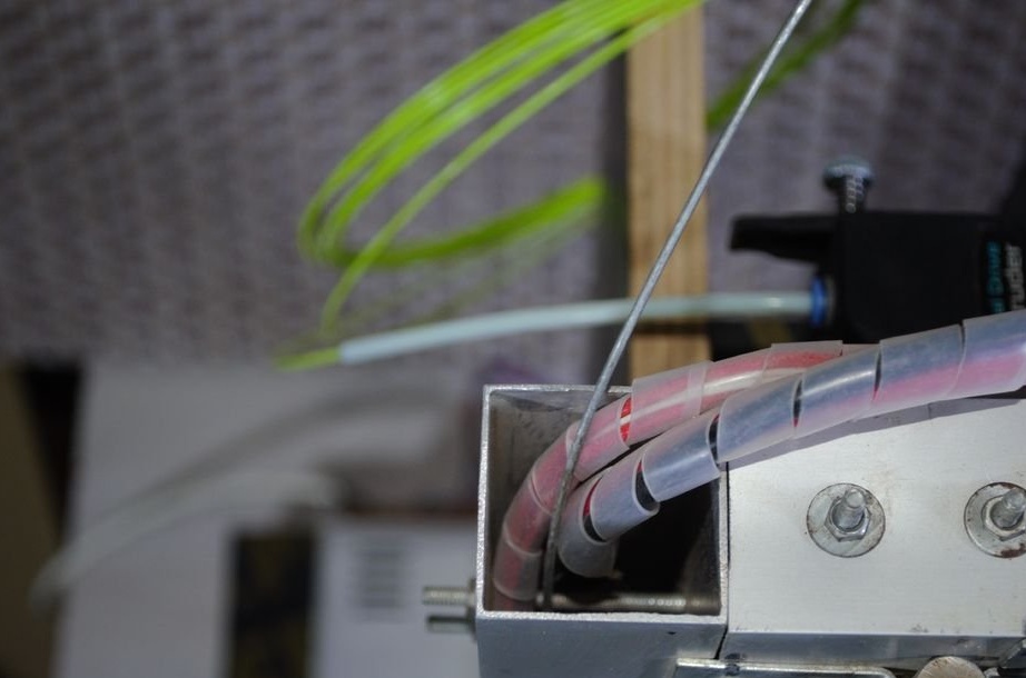
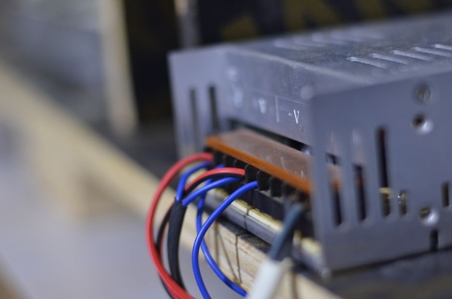
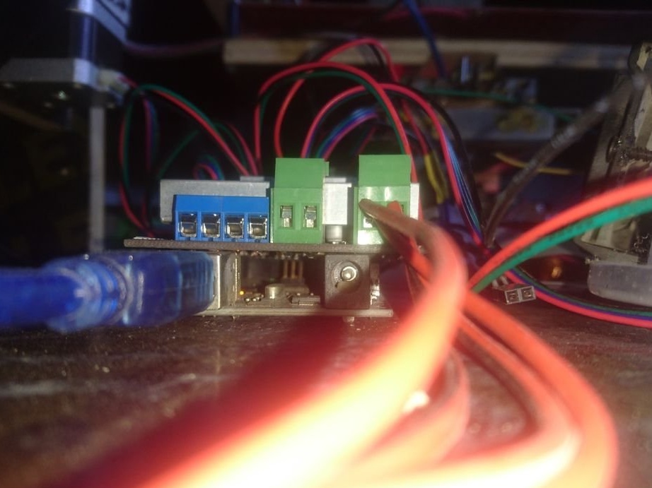
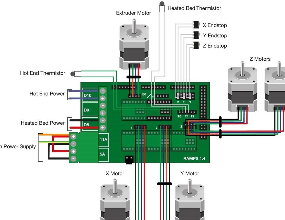
Step Eight: Wiring
Performs electrical installation.
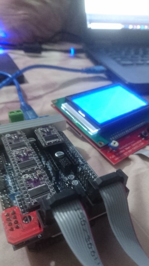

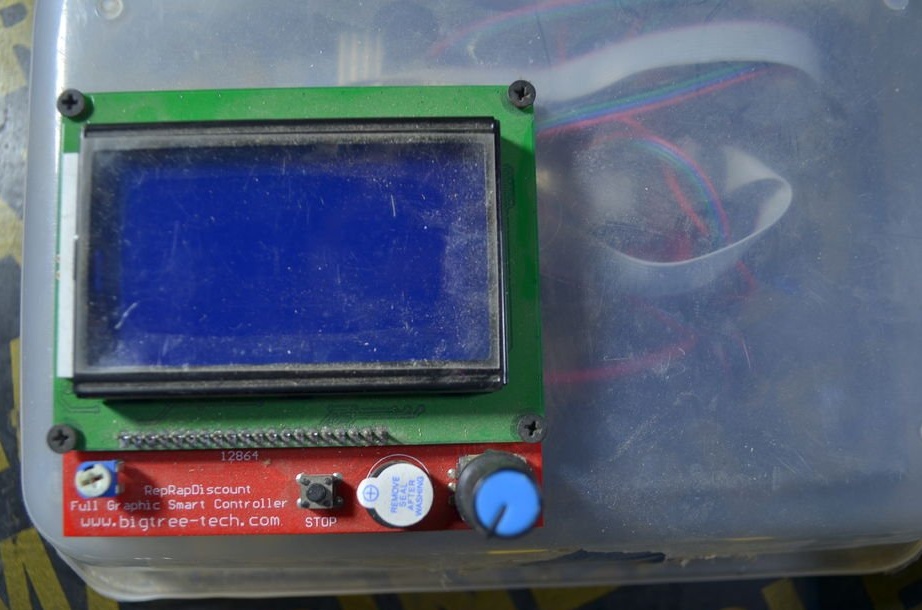
Installs the firmware.
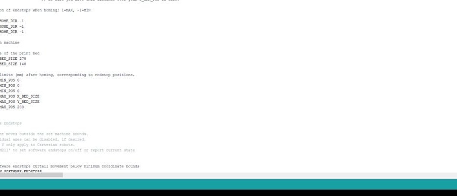
You can download the firmware here.
The wizard also provides 3D models.
Download models and edit to your sizes below.
X axis
Y axis
Z axis
Full model
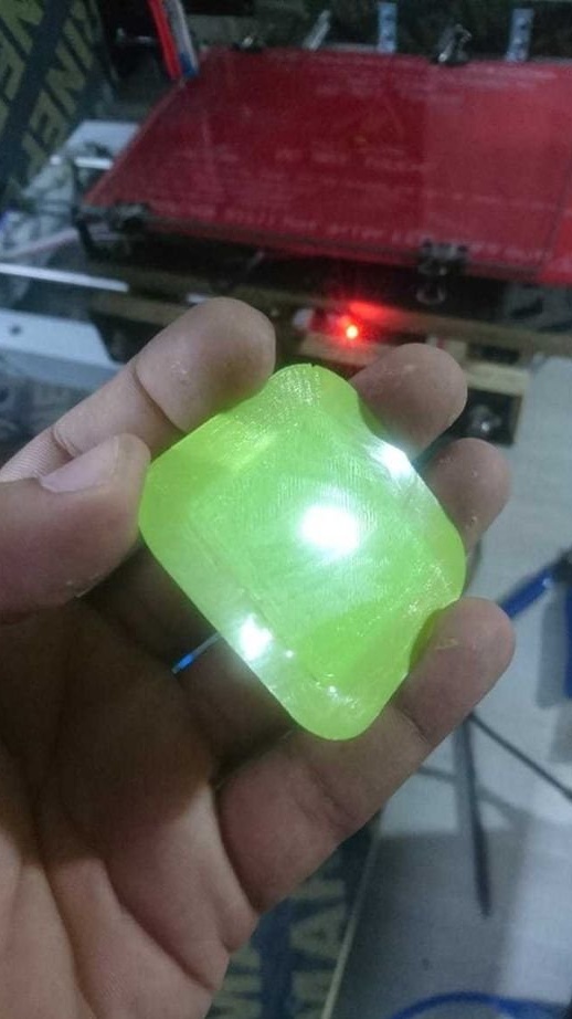
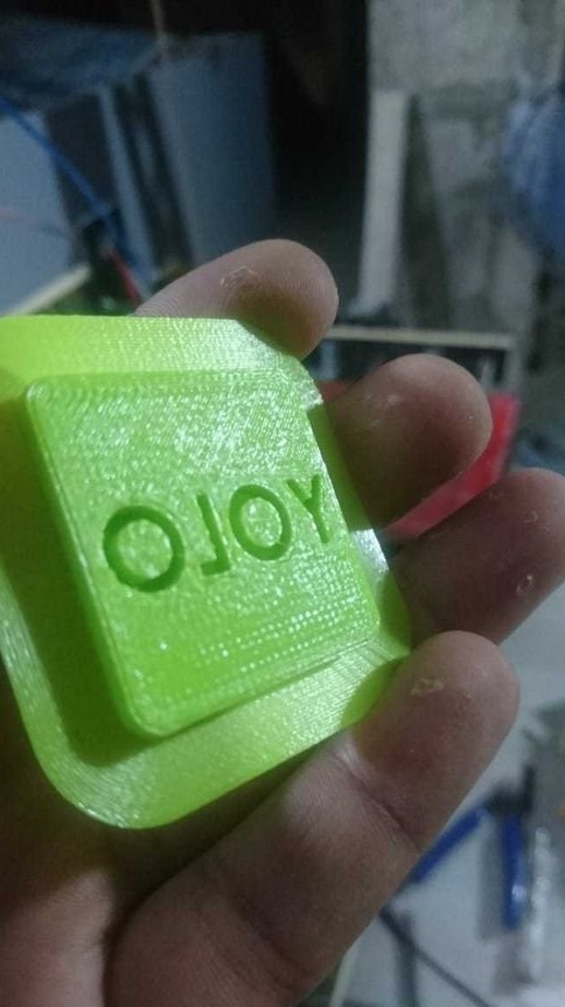
All is ready.