

Hello to all lovers homemade, as well as those who like to take videos, as this article will be useful to you.
Many who are engaged in video shooting know that you can get a good picture provided that you have a good camera shoot, and also have good lighting. But how to get out of the situation, if the camera is good, but the lighting is poor, an autonomous searchlight will certainly help here, which will serve as an on-camera light, the creation of which I will discuss in this article. The main task was autonomy, as well as reliability. All components can be purchased at electronics stores or in China through an online order. Before proceeding with the assembly of the searchlight, we will determine what we need for this.
In order to make a home-made on-camera light, we need:
* Spotlight purchased at the store.
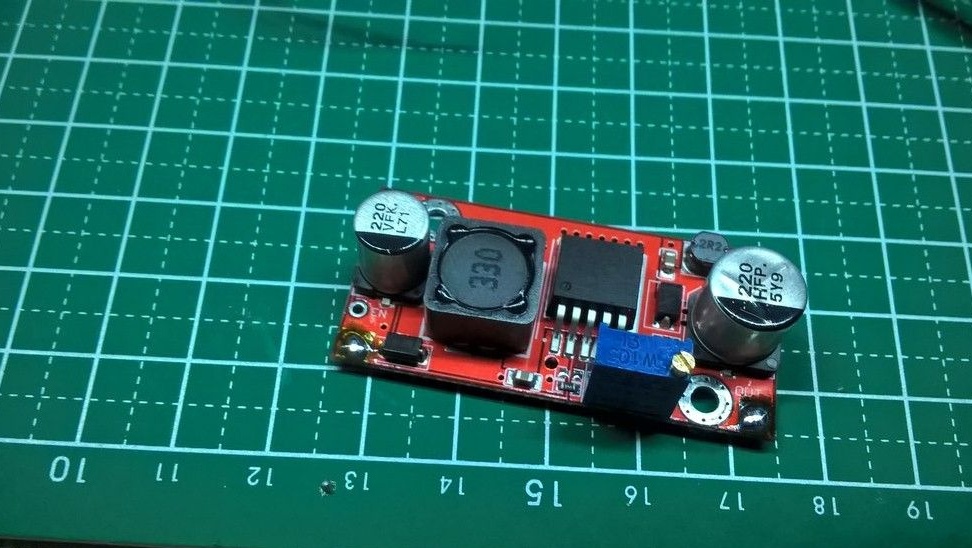
* Boost module to get about 30V output.
* Charging module for 18650 battery.
* 18650 battery.
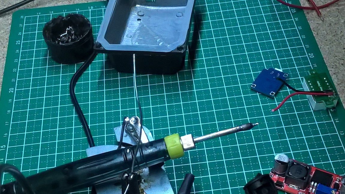
* Soldering iron.
* Rosin and solder.
* Wires.
* Power button.
* Shrink.
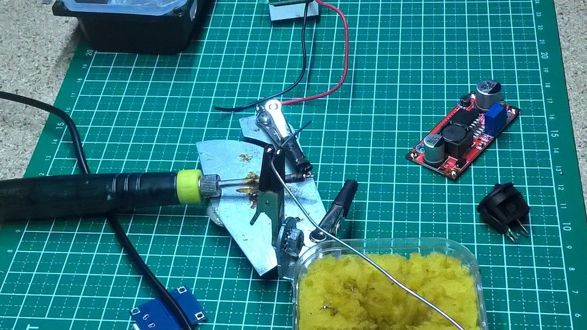
* Assistant or "third hand".
* Files round and square.
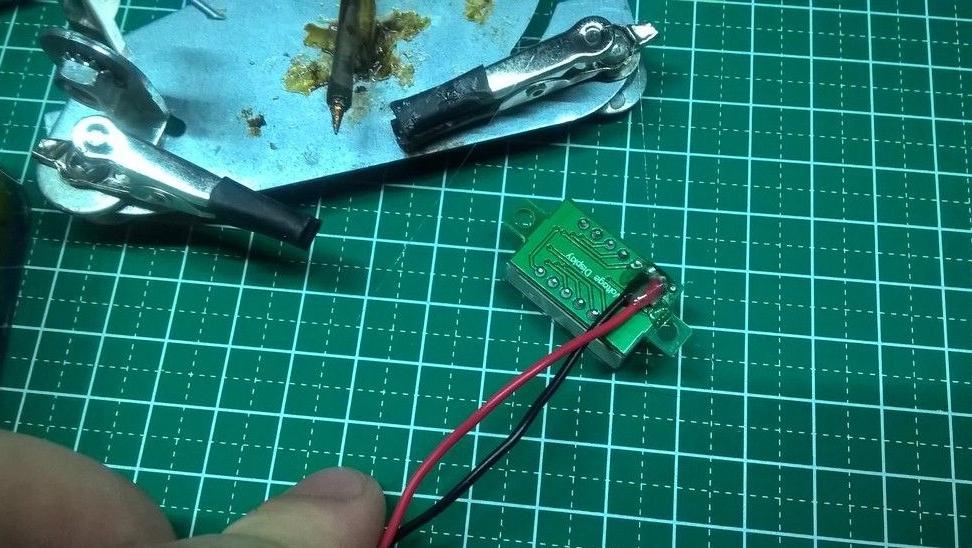
* Voltmeter.
* Double-sided tape.
* Hot melt adhesive.
* Thermal grease or thermal pad.
* Insulation tape.
That's all you need to build an autonomous spotlight, most of the parts purchased in China.
We proceed directly to the assembly.
See the build process here.
Step one.
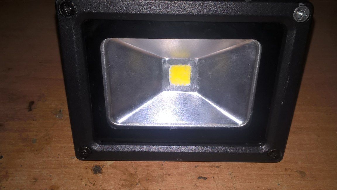
Let's start from the very beginning, we need a spotlight, which I purchased in a store, it cost me about 400 rubles and had a 10-watt LED on board, which was powered by a power supply installed in a case with an output voltage of 30 V.
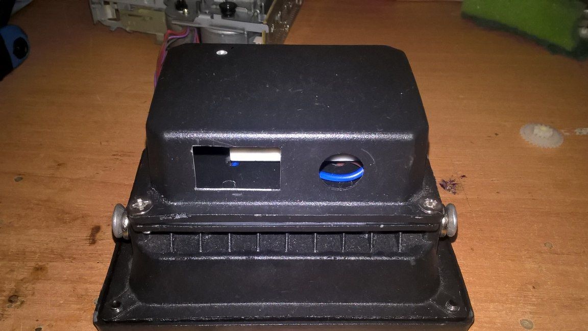
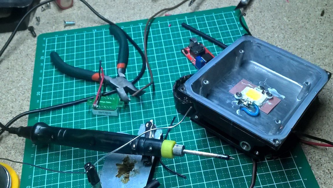
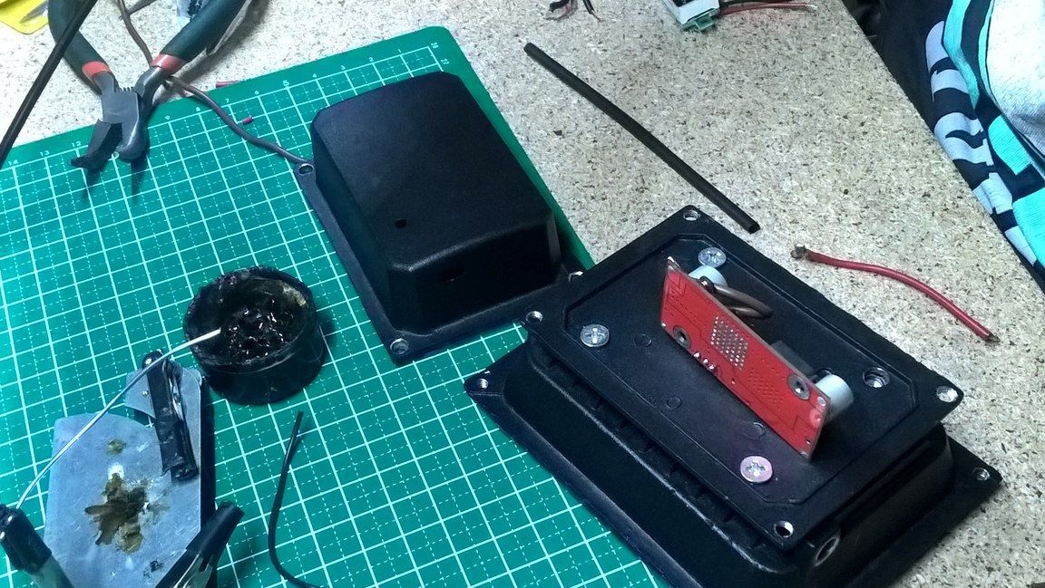
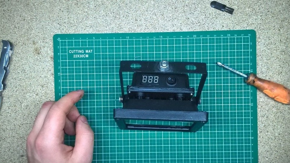
In the compartment where the block was previously located, you need to make a hole for the voltmeter, the charging module light bulb, the switch and the USB plug. This is all done quite easily, but it takes time, in this case we work with a file. In the process, we check how the components are installed, like a voltmeter, etc., if everything went well, then go on.
Step Two
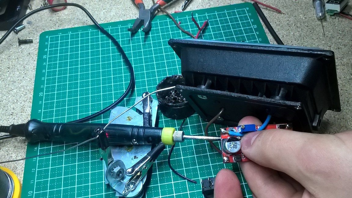
We approximately install the components in those places as planned and check that there is enough space for installation. With a tuning resistor, we set up a boost module to get 28 V at the output, and at the input we have the same 18650, the maximum voltage of which is 4.2 V.
The connection scheme is as follows, first the terminals go from the 18650 battery to the charging module, then the minus of the battery goes to the voltmeter and it goes to the boost module, the minus and plus of which goes directly to the LED, and the plus of the module is connected to the gap by the voltmeter with the plus of the battery . The video also details how to connect all the details.
Step Three
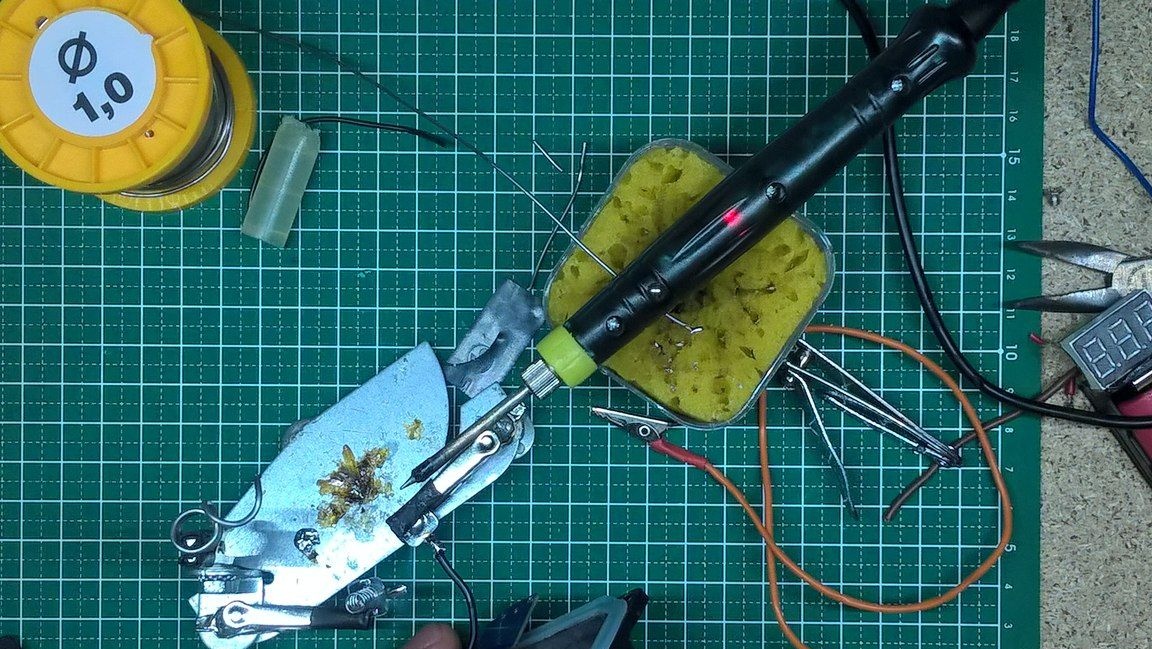
Now turn on the soldering iron and wait until it warms up to working temperature, after which we tin the sting to get to work. The first thing we solder the wires to is a voltmeter, solder the small wires and clean the solder spots from the remains of the flux.
The voltmeter will be attached using hot melt adhesive. We turn to the boost module, do the same thing as with a voltmeter, for convenience we do this with a "third hand", and you can fix it on a double-sided tape, which will not allow the module case to accidentally close.
Do not forget to remove the flux residues at the end of the soldering of each element, since this can adversely affect the operation of the entire system as a whole.
Step Four
Now we will deal with the main hero of the occasion, namely the LED. Solder the wires to the LED, which is mounted on thermal grease and secured with bolts in the spotlight.
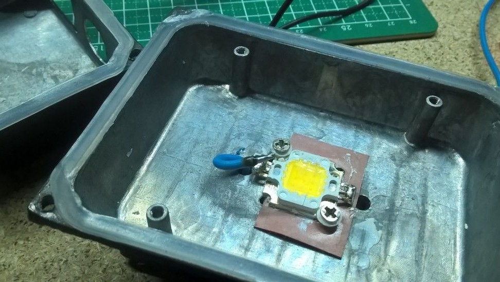
Also try not to overheat the LED, as its overheating will order it to "live long." Solder the wires of the boost module to the LED.
The LED is soldered, you can check, but at the same time and see if the voltmeter is working. If everything is successful, then move on.
Next, solder the wires to the charging module, then attach it to hot-melt adhesive in the spotlight body.
Please note that the input of the module must fit snugly in the spotlight, otherwise it will stagger and may break off afterwards. Wearing heat shrink on the wires, solder them to the switch according to the scheme.
Step Five
The case is protected by an insulating tape from accidental short circuits, and a double-sided tape is also perfect.
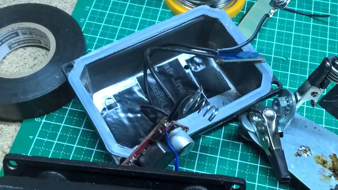
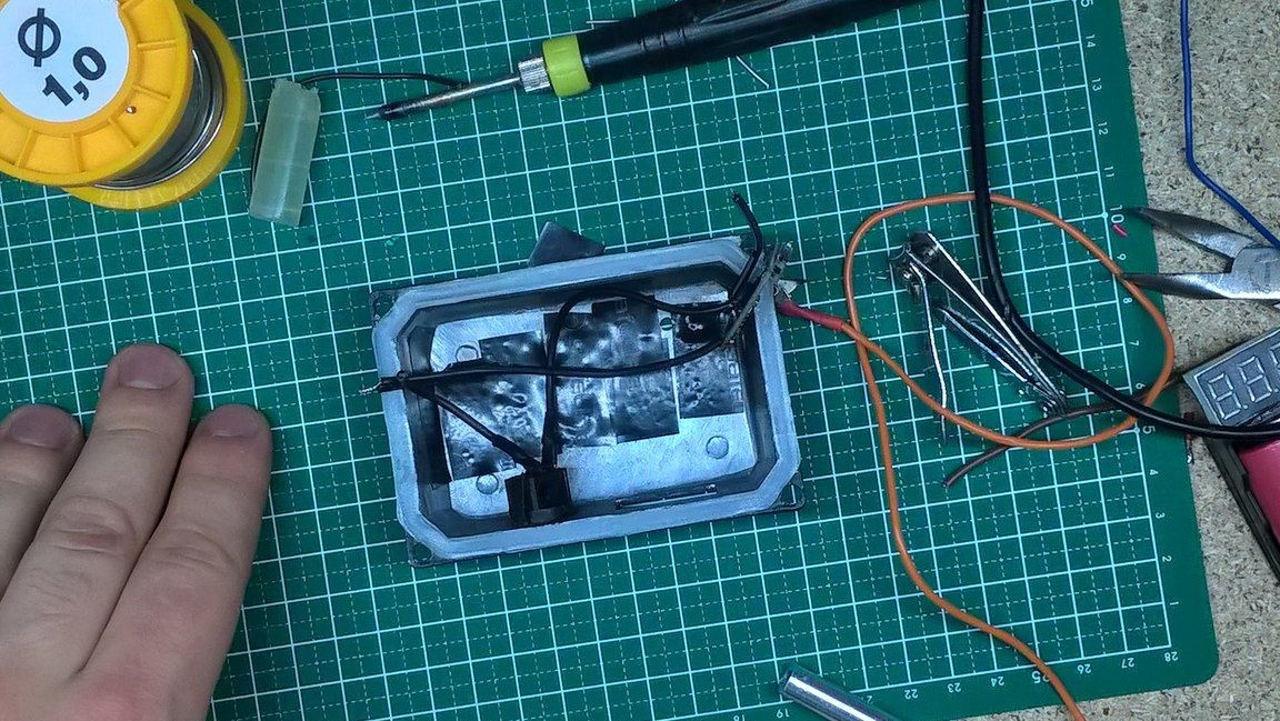
Soldering wires to the battery itself is not so convenient, so it was decided to make connections using springs borrowed from the battery box, solder them to two wires, and then glue the hot melt to the case and put the battery.
Step Six
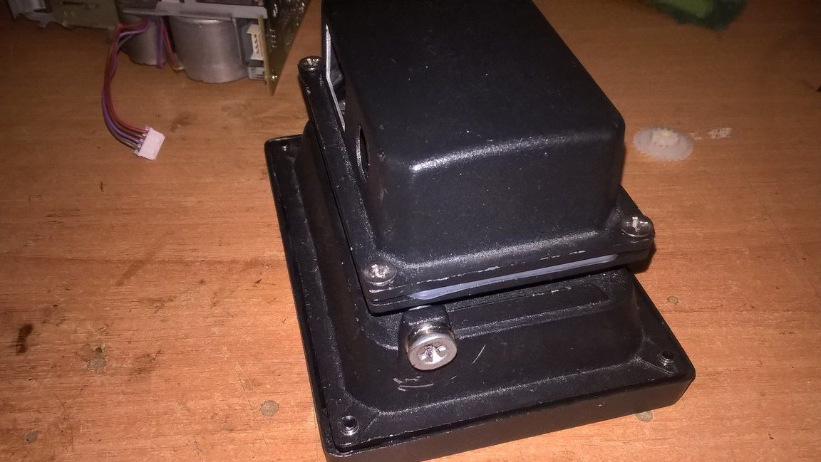
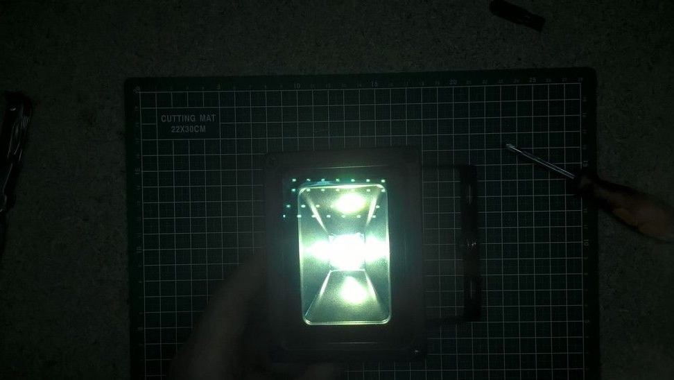
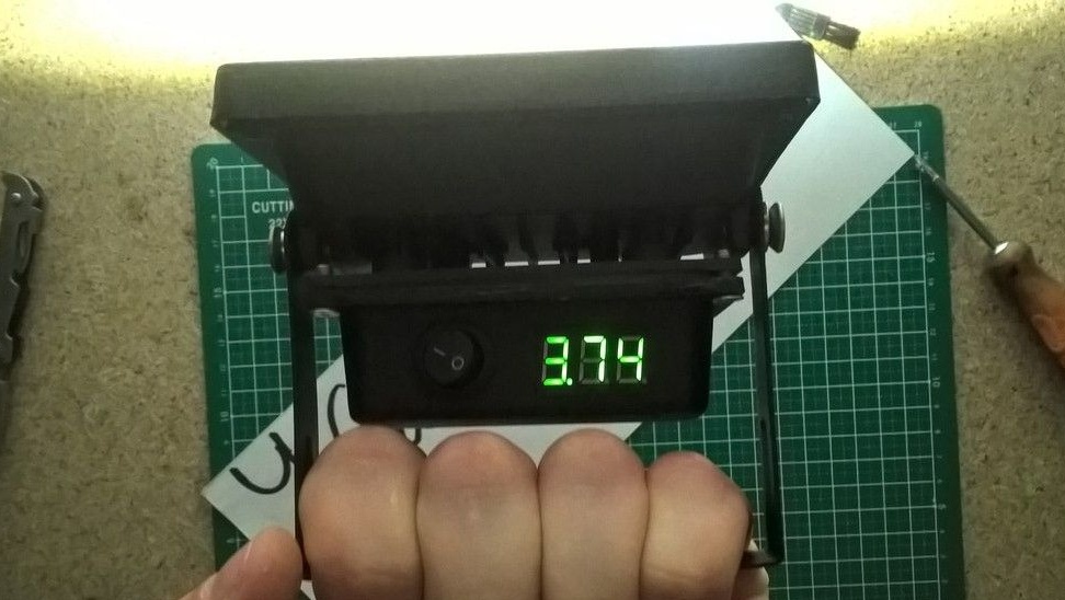
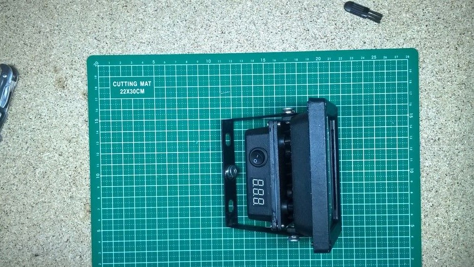
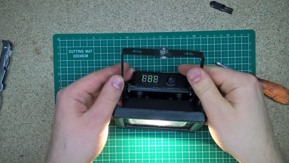
Having installed all the insides and twisting the housing, you can check the spotlight for operability and the functioning of indicators, we also fasten the mount on the housing, which can later be fixed in a place convenient for you. With the switch, we put the spotlight in working condition, in the dark it can be seen that the voltmeter is working and shows the voltage at the battery terminals, it will be convenient to use it to monitor the battery discharge and roughly estimate how long it will last.
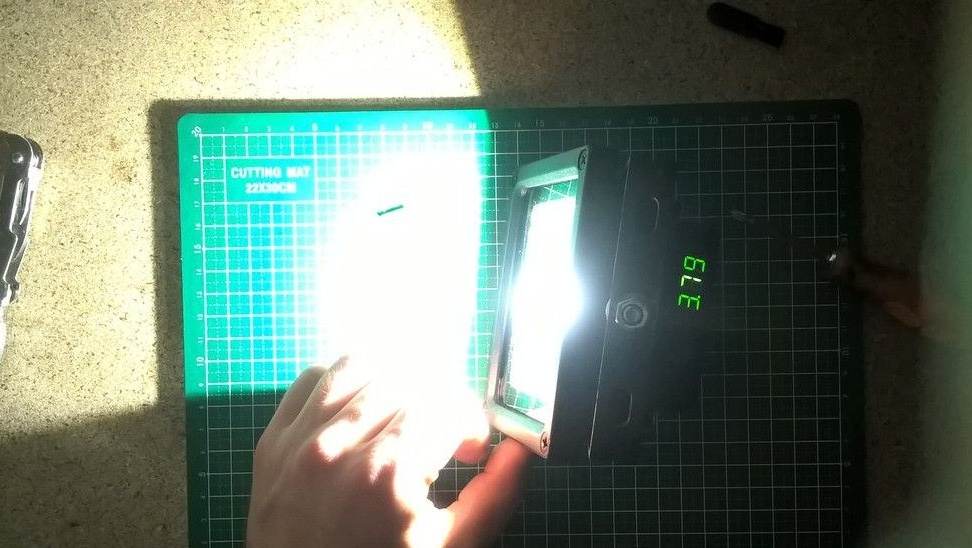
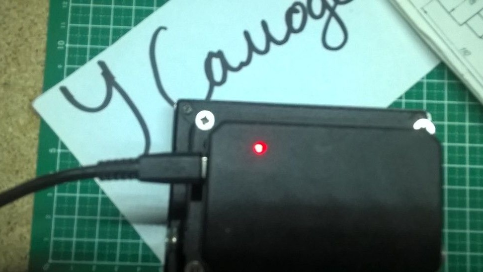
We also check the charge module, when the charger is connected, the bulb lights up red, which indexes us from the fact that the battery is not charged, the blue color of the bulb indicates that charging is complete and the spotlight is completely ready for use.
The homemade product is ready for this, the floodlight turned out as it was intended, namely autonomous, bright and reliable, thanks to the not well-known 18650 battery and a 10-watt LED.
Thank you all for your attention and creative ideas to all.