Good day dear the inhabitants of our site!
The proposed device enables the lamp to be turned on using a button without fixing.
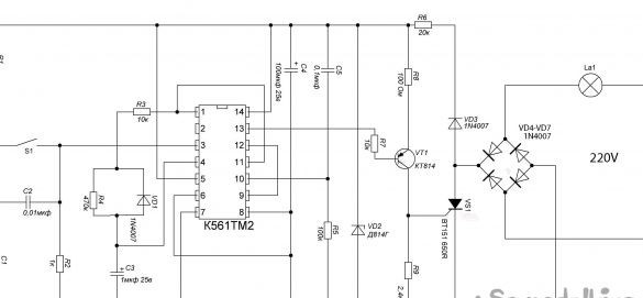
The device is powered by AC 220 V using a rectifier bridge VD4-VD7. The lamp lamp is included in one diagonal of the bridge, and the thyristor VS1 in the other. The lamp lights up only if the thyristor is open. The maximum lamp power is determined by the permissible rectified current of the bridge diodes and when using 1N4007 diodes is 100 W
Step one
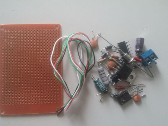
We need a breadboard, a convenient thing for assembling and configuring devices. A soldering iron, wires, solder and a bunch of radio components according to the list.
Radio Parts List
9pcs R1-330k, R2-1k, R3-10k, R4-470k, R5-100k, R6-20k, R7-10k, R8-100ohm, R9-2.4k resistors
Capacitors 5pcs C1, C2-0.01mkf, C3-1mkf 25v, S4-100mkf 25v, C5-0.1mkf
Diodes 6pcs 1N4007
Zener diode VD2 D814G
Transistor VT1 KT814B
Thyristor VS1 BT151-650R
Chip K561TM2
Power connector
Button without fixing
Second step
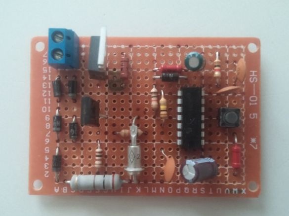
We solder all our radio components as shown in the diagram
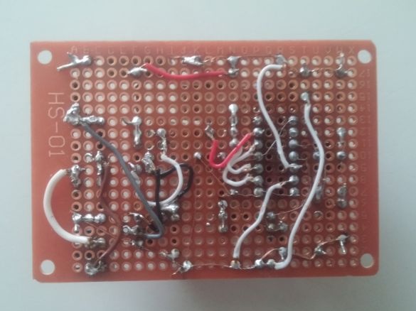
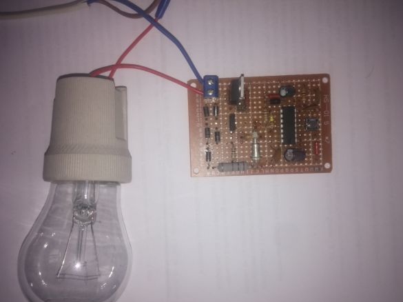
I got it like this.
Step three
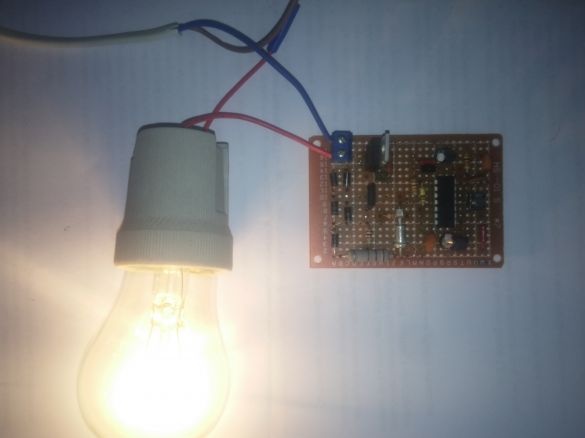
Checking the operation of the circuit, my circuit worked the first time! Attention in the circuit there is a life-threatening voltage of 220 V so use all safety precautions!
It is advisable to use a resistor of R6 20k with a power of 2W since it heats up during operation
Thyristor VS1 can be replaced by domestic KU202N, KU202K
Chip K561TM2 can be replaced with a foreign analog CD4013
When the device is operating for about two hours with a 60W lamp, heating the parts is not a significant radiator on the transistor and thyristor can be omitted
It was a prototype of the device fully configured and tested, in the future I will reduce it by 2 times and will use it as a passage switch!
A short video on the operation of the device
I hope my homemade product will be useful for both beginners and experienced radio amateurs!
See you all! See you soon!


