In this case, the circuit allows you to independently turn on and off the lighting, both from the remote control and through the manual switch.
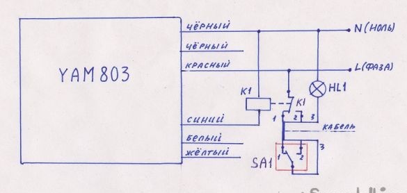
A circuit based on the YAM-803 switch has been created, but other options are possible. It is simple enough and does not cause special difficulties in assembly. Three intermediate relays for 220 volts with a contact current of at least 5A and three pass-through switches are enough if you decide to use all three channels. Consider this device as an example of one channel (additional will be identical). Intermediate relay K1 is connected
(see diagram) between the phase output wire (let it be blue) and the common neutral wire (black). And the contacts of the relay and switch SA1 are connected, as shown in the diagram. At the same time, this combination allows you to turn the load on and off independently, that is, both using the remote control and manually, with a passage switch. It is advisable to install the relay next to the remote switch of the module, and the switches in any convenient place. The switches are connected to the circuit with a 3-core cable, with a cross section of at least 1.5 mm2.
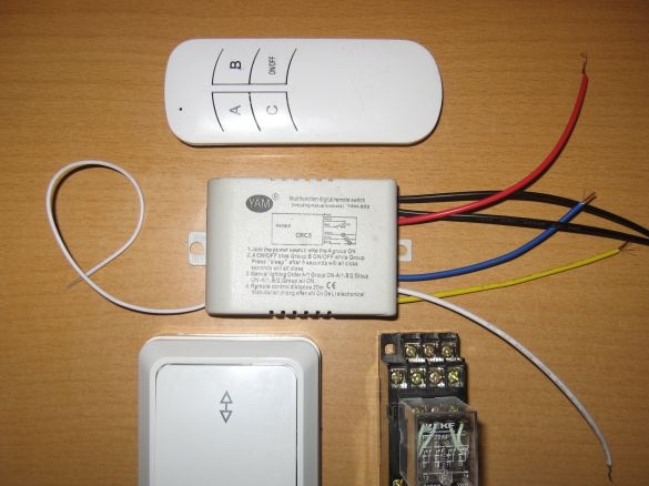
Figure 2 shows all the parts involved in this scheme, except for an incandescent lamp (lamp). The remote control is included in the kit of the remote switch and is not shown in the diagram (Figure 1).
Picture 1.
Figure 2


