

The circuit is based on the NE555 universal timer and decimal counter with the K561IE8 decoder.
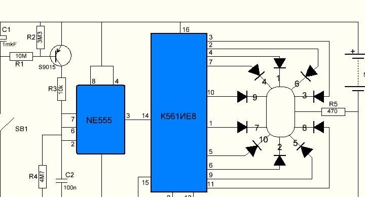
When the clock button SB1 is pressed, the electrolytic capacitor C1 is charged. Its capacity is 10 times greater than the capacity of the frequency-setting non-polar capacitor C2. Therefore, when the button is released, the charge of this large capacitor is enough for many more charge-discharge cycles of the frequency-setting capacitor. In this case, the voltage at the electrolytic capacitor C1 gradually decreases during the discharge process, and more and more time is spent on the charge of the frequency-setting capacitor C2. And the spectacular effect of the gradual stop of the "roulette" is achieved.
Materials:
microcircuit NE555 (domestic analogue KR1006VI1);
K561IE8 chip (foreign analogue of CD4017);
transistor S9015 (PNP transistor);
LEDs 10 pcs;
clock button;
electrolytic capacitor 1uF;
non-polar capacitor 0.1 uF;
470 ohm resistor;
10 kΩ resistor
3.3 megohm resistor;
4.7 megohm resistor;
10 MΩ resistor;
AA-3pcs battery;
wires
textolite foil.
Instruments:
soldering iron, solder, flux;
electric drill;
glue gun;
drill
Step-by-step instructions for manufacturing LED roulette
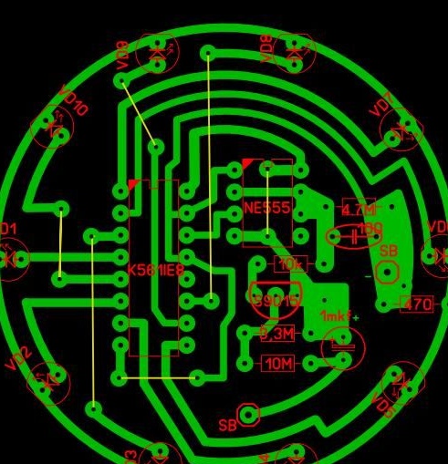
To get started, I drew a printed circuit board in the program SprintLayout_6.0 with a convenient arrangement of parts for me
Transferred the image to foil textolite according to the LUT method (laser-ironing technology - the Internet is full of descriptions of this process).
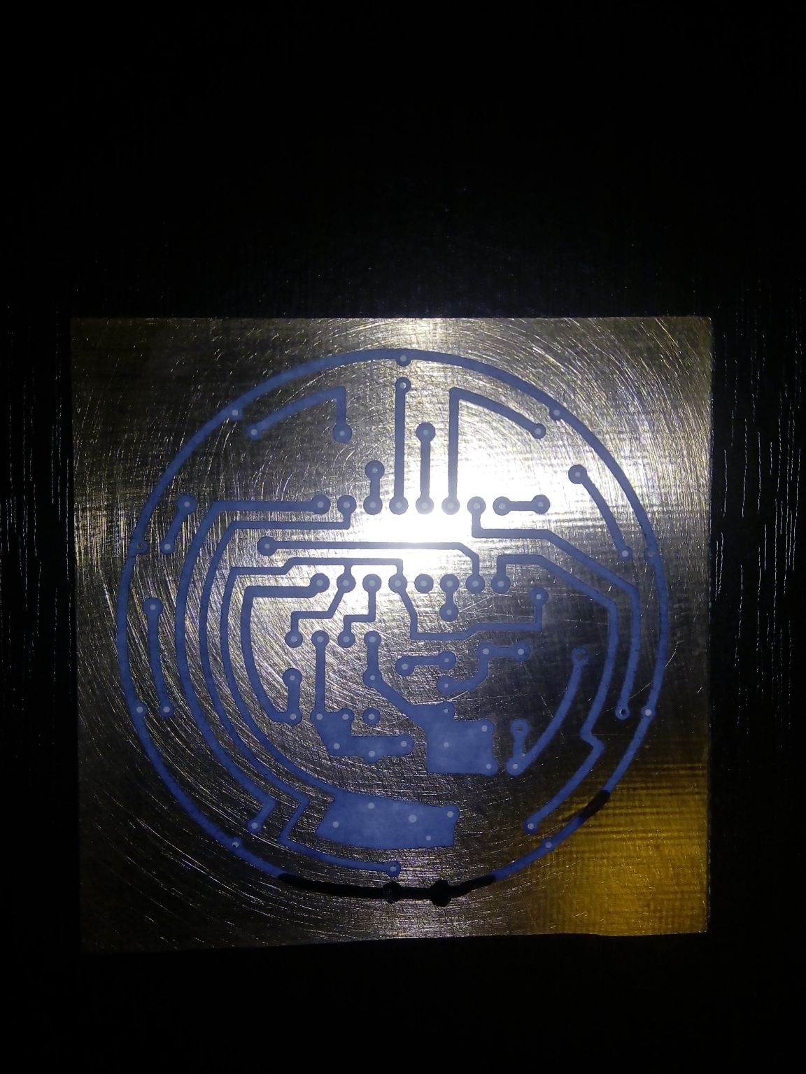
Etched board in etching solution. As such a solution, I use hydrogen peroxide in combination with citric acid. He drilled holes on the printed circuit board and tinned printed current paths with tin-lead solder.
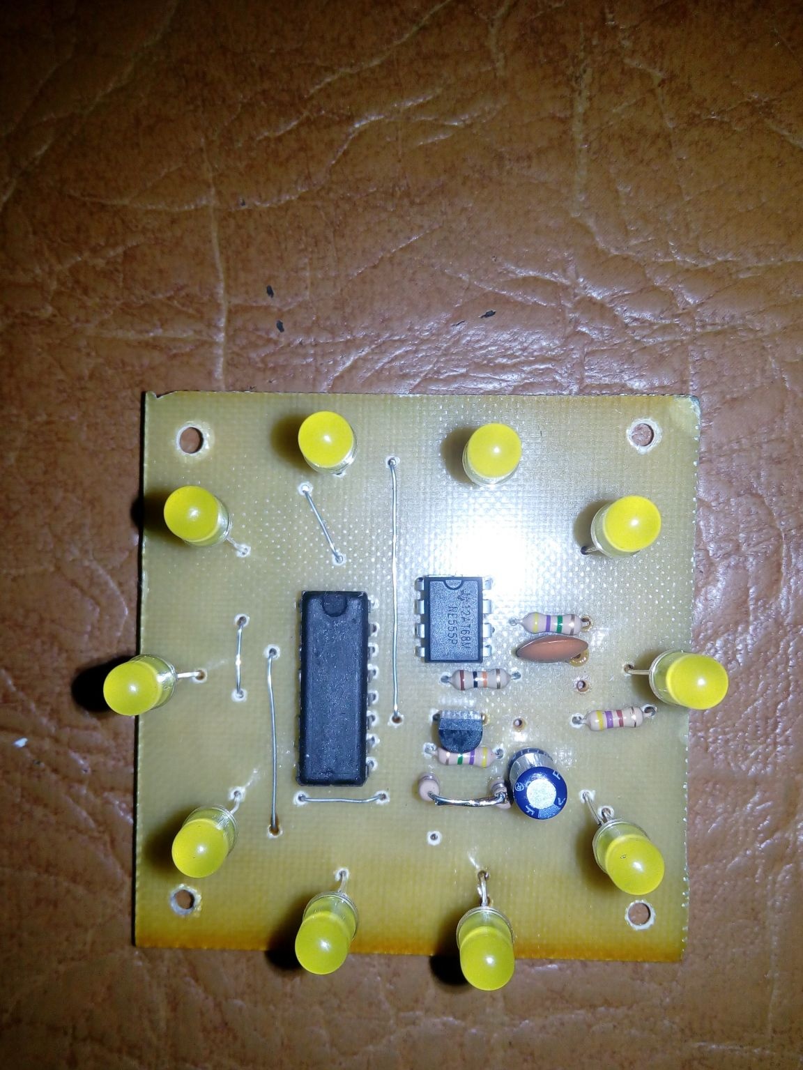
I soldered the radio components on the printed circuit board in accordance with the circuit diagram. I took out the clock button for starting roulette to the housing of the finished device, so it is not on the printed circuit board.
Transistor S9015 can be replaced with any low-power transistor PNP structure, taking into account the location of the conclusions.
It is possible to replace NE555 with a domestic analogue KR1006VI1 or foreign analogues ICM7555, LM555, AN1555 and others (different manufacturers, but the purpose does not change).
The K561IE8 chip can be replaced with a foreign analogue of CD4017.
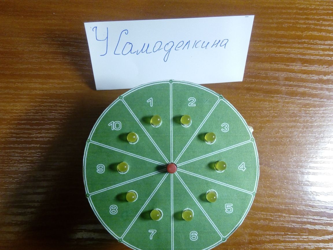
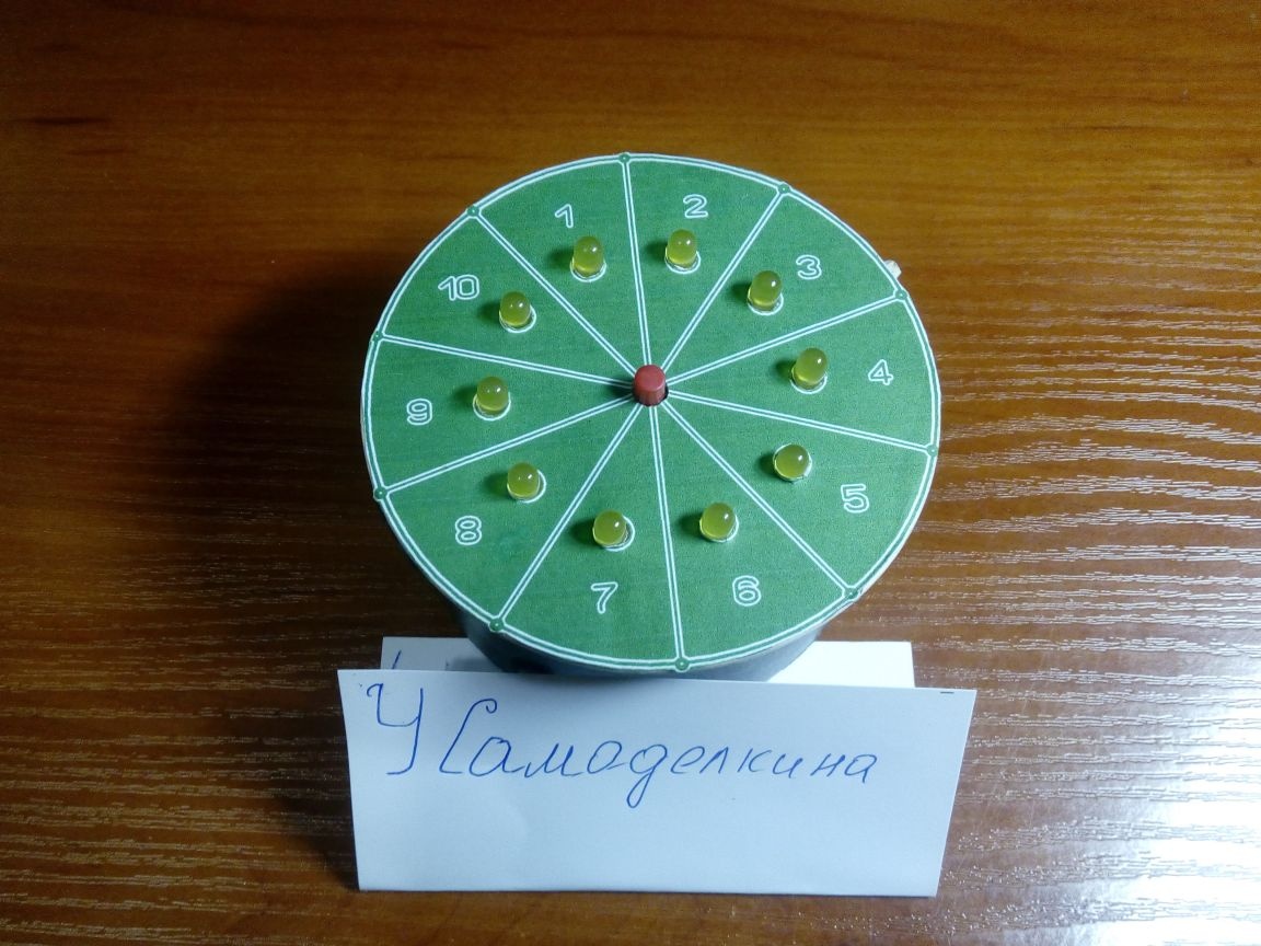
I used LEDs with a diameter of 5 mm bright, yellow glow, although as an experiment I tried both green and red - it works with them.
The duration of LED flashing (roulette rotation) depends on the time-consuming R4 and C2, which can be changed to fit your needs. With the R4 and C2 indicated on the circuit diagram, the LED flashing time is 22 s. To increase the duration, it is necessary to reduce R4 or increase C2, to reduce the duration of the “rotation”, perform the opposite actions.
The resistance R2 was replaced by 4.7MOhm, and R1 was replaced by two resistors also connected in series with 4.7MOhm. Only those were available, hence the replacement.
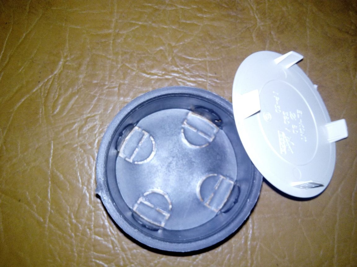
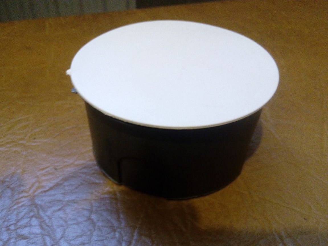
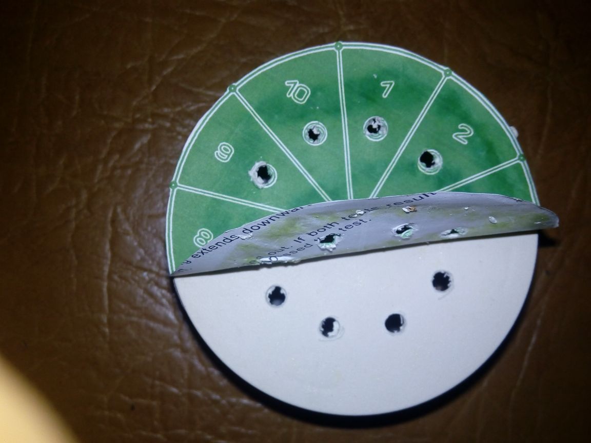
I did not bother with the manufacture of the case, but took the first suitable one and adjusted the dimensions of the printed circuit board for it. This turned out to be a junction box for wiring.
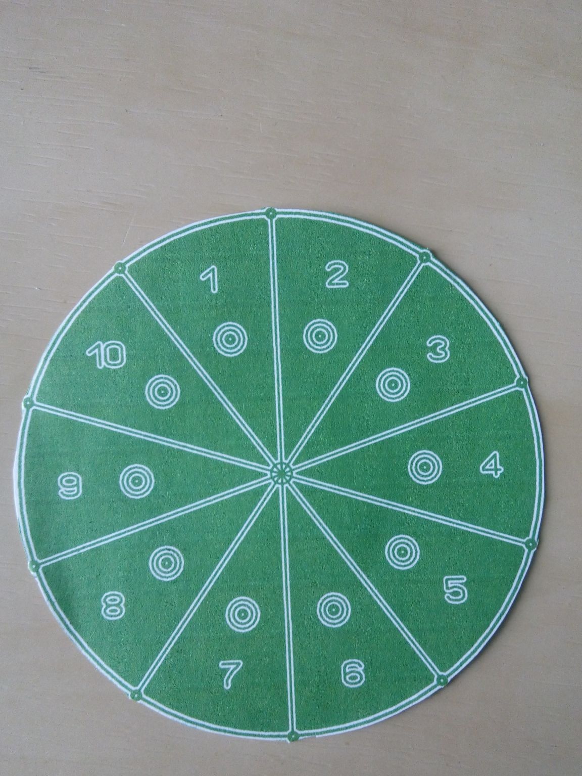
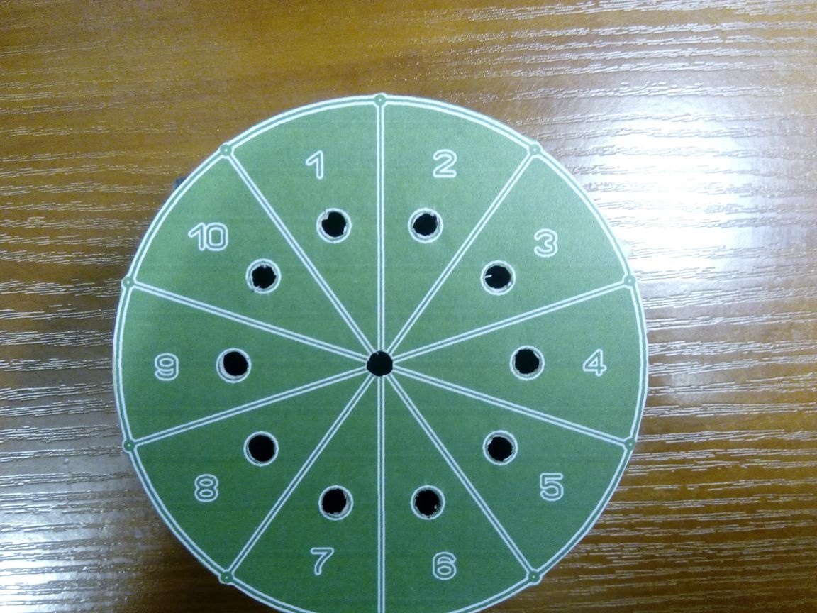
I made a marking for the LEDs and a clock button on a piece of paper, which will become the working field for the LED roulette, and glued it to the case.
Drilled holes with an electric drill
I installed the finished circuit in the case and additionally fixed the LEDs with hot glue.
I used 3 AA batteries to power the device. It is possible to use a 5V power supply from household appliances.
Conclusion
The LED roulette scheme is easy to repeat, so even a novice ham radio can assemble it. The circuit works immediately after assembly and does not need adjustment, provided that the radio components are in good condition and properly installed.
A simple game will be something new for you and your environment, which will bring joy and pleasure!