
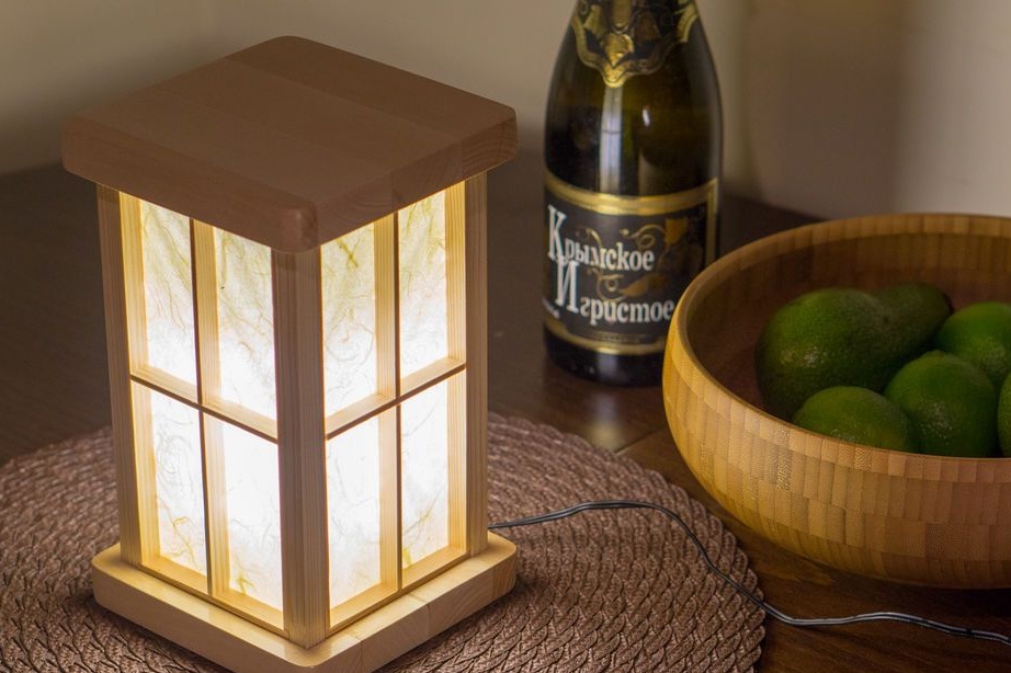
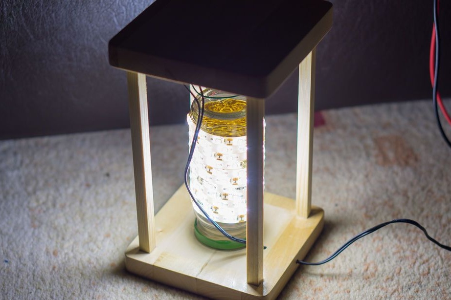
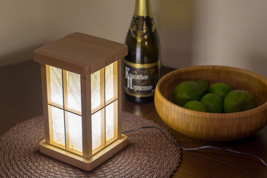
In this article, we will consider the manufacture of an LED lamp with touch control. If you bring your hand to the top surface, the lamp lights up. A second gesture turns off the lamp. Let's watch a video showing the lamp.
For the manufacture of the lamp master master needed the following
Tools and materials:
-Board;
-Bar;
-Rail;
-Rice paper;
- Electric jigsaw;
- Clamps;
-Pencil;
-Gon;
-Grinding unit;
-Hacksaw;
-Bit;
-Glue;
-Dremel;
-The wire;
-Drill;
-Varnish;
- Paint tape;
-12V power supply;
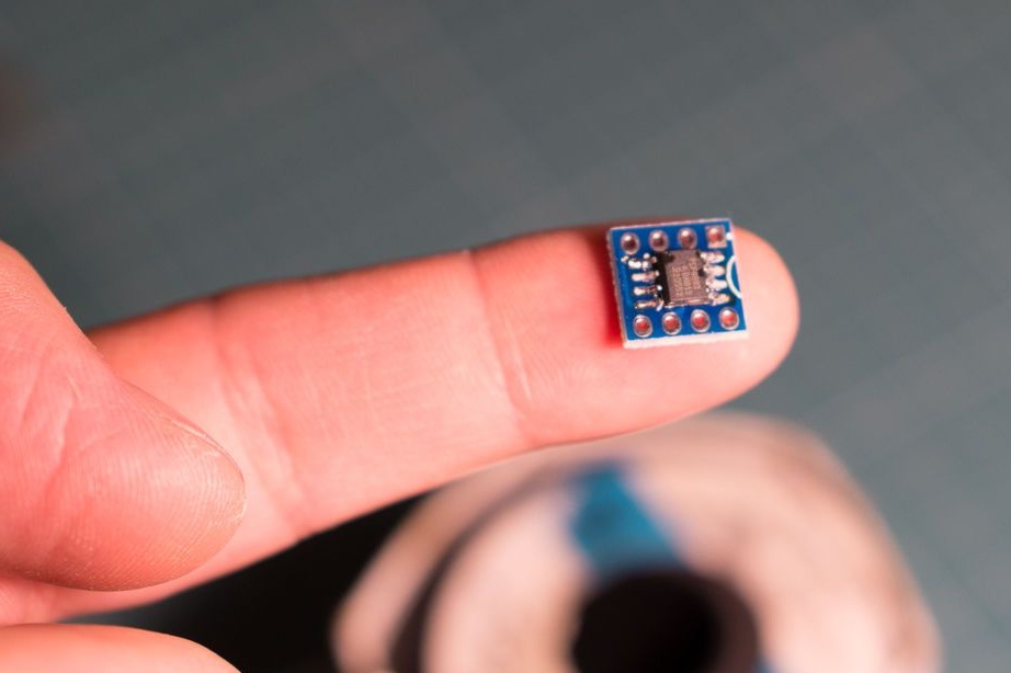
- Microcircuit PCF8883;
- SOIC8 board adapter;
Transistor IRF 520;
-Circuit board;
- Voltage Regulator LM7805;
-Capacitors;
-LED Strip Light;
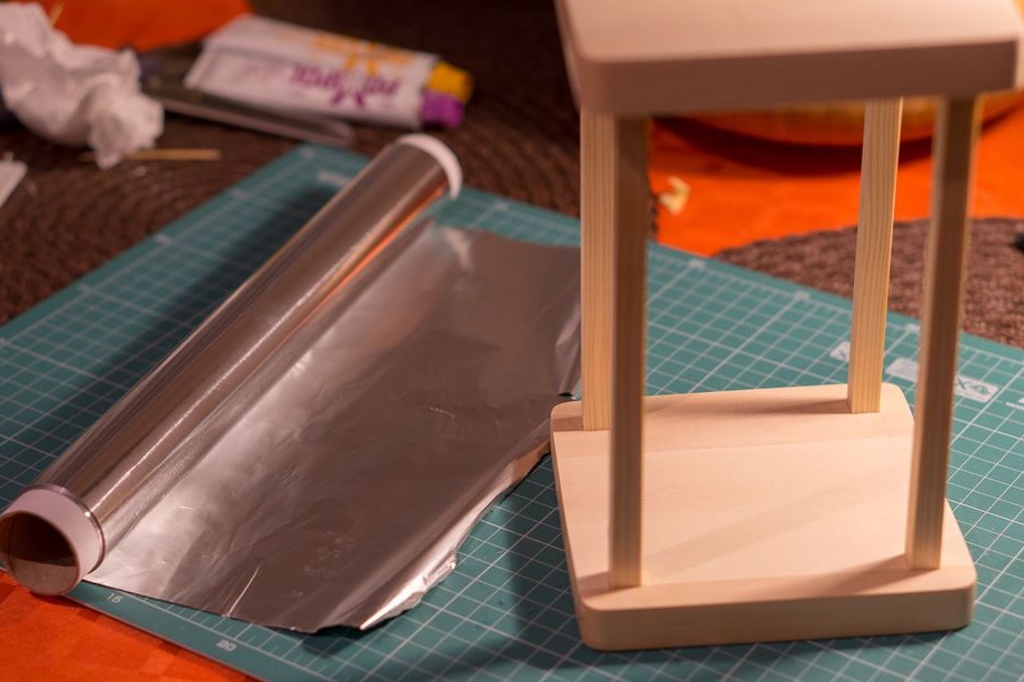
-Foil;
-Glass jar with a screw cap;
-Screwdriver;
-Fasteners;
-Knife;
-Soldering iron;
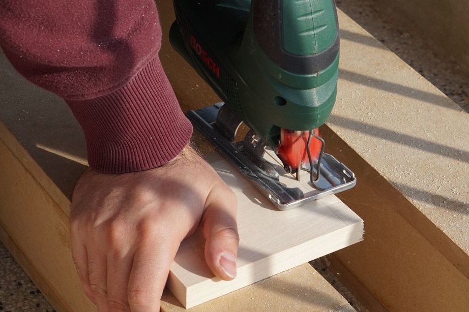
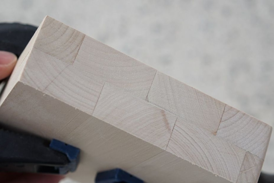
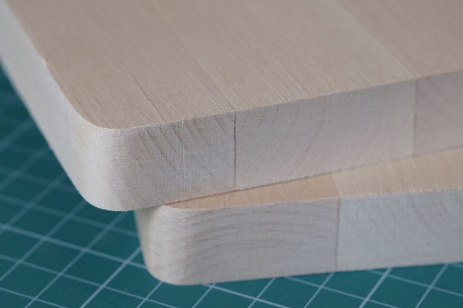
Step One: Top and Bottom
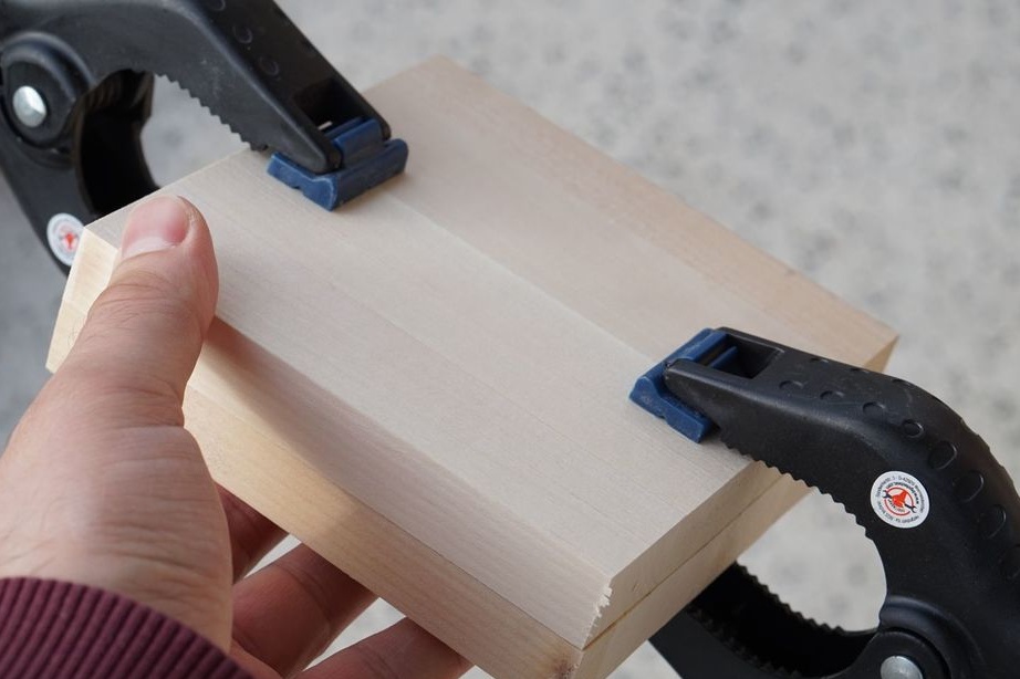
From the board, the master cuts out two 13 * 13 cm squares with a jigsaw. He clamps the workpiece with clamps and grinds the surface. Rounds corners of preparations.
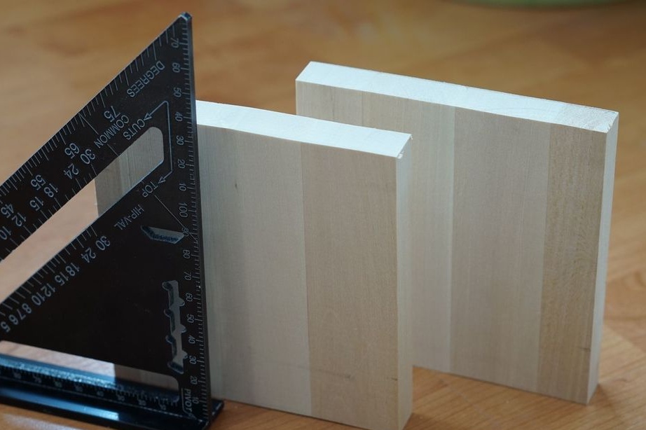
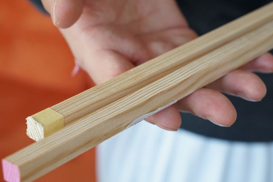
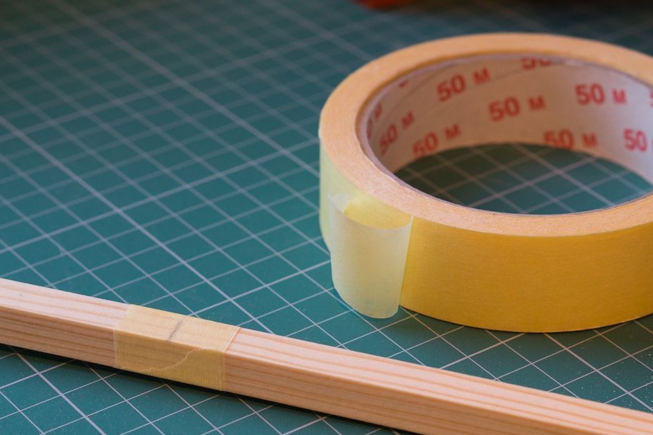
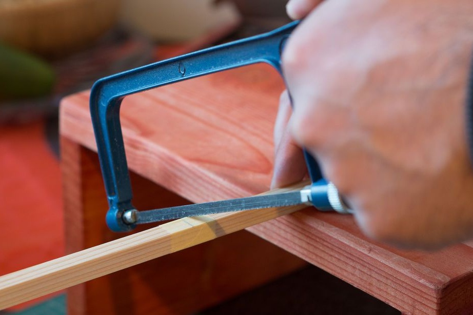
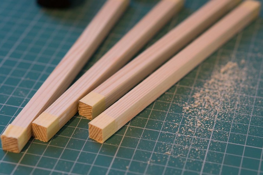
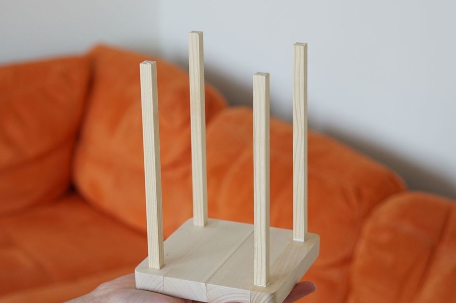
Step Two: Racks
Four racks 19 cm long are cut from a 1 * 1 cm bar. To prevent chipping, a masking tape is glued before sawing. Grinds them.

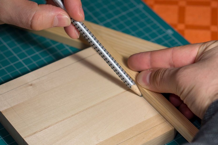
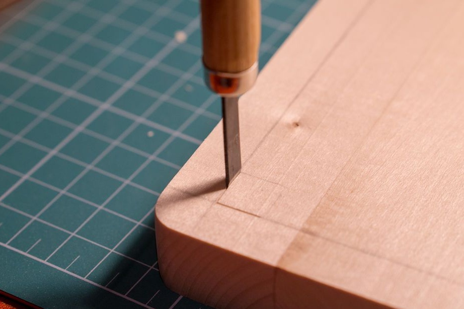
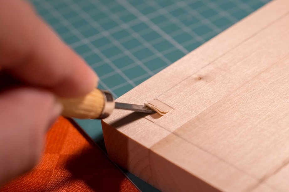
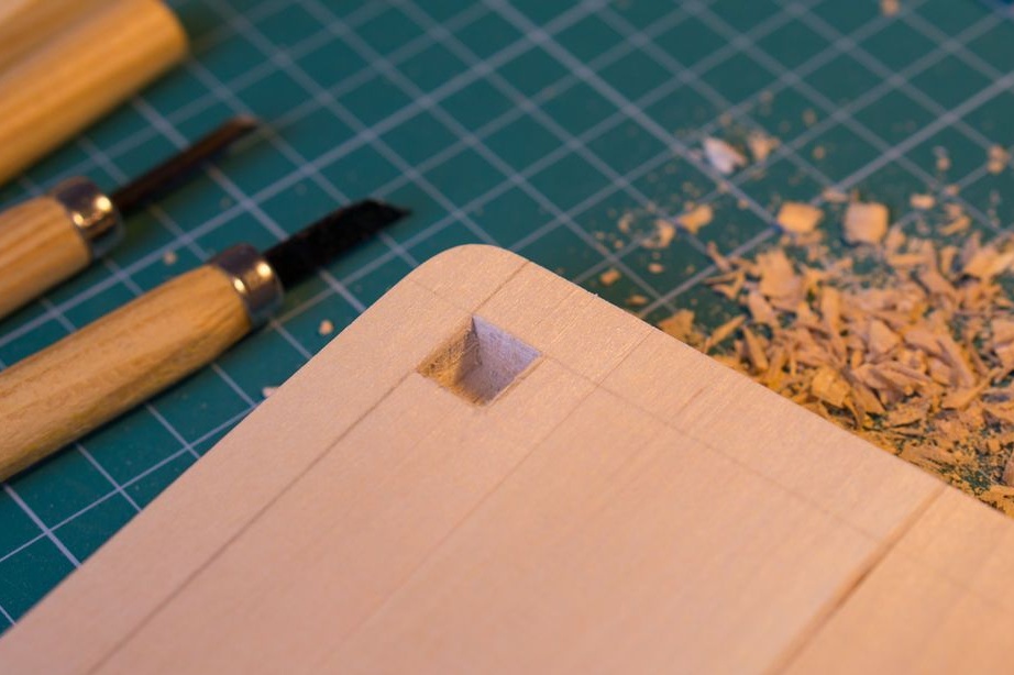
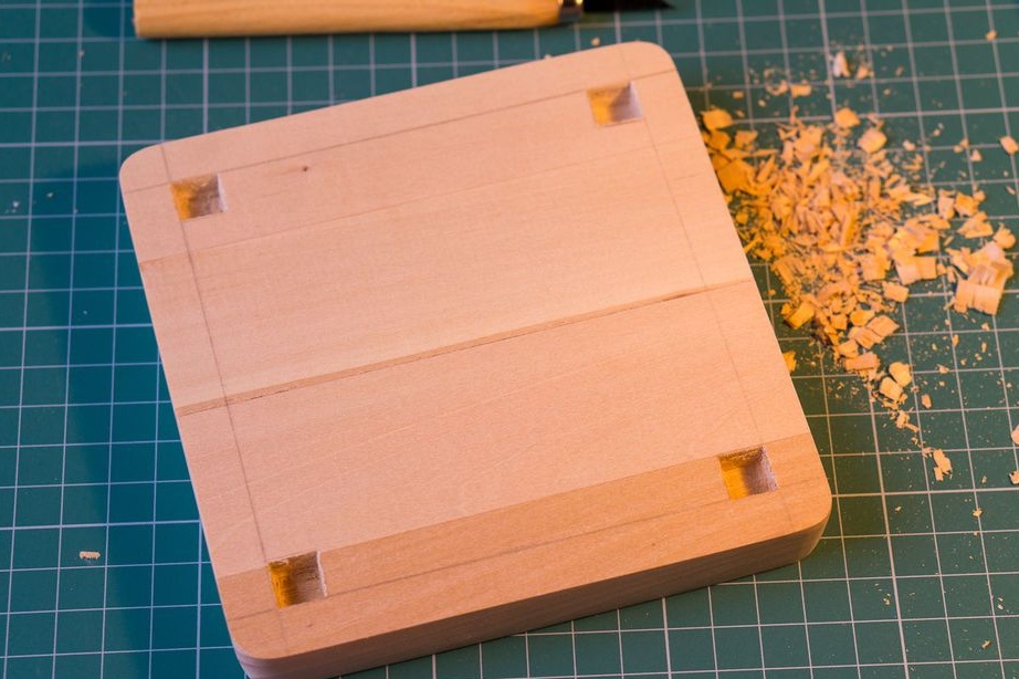
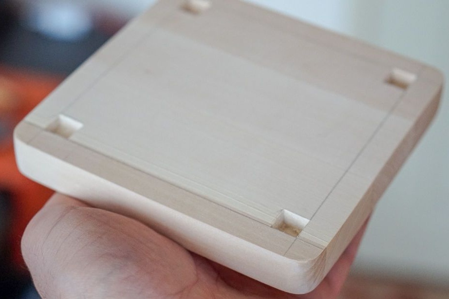
Step Three: Bottom
Makes markup on the workpiece. Selects 1 * 1 cm grooves in the corners. Grinds again.
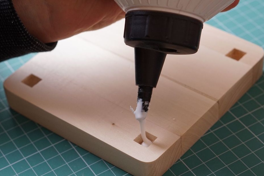
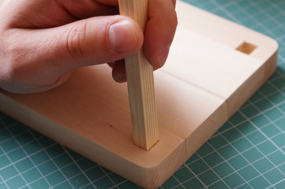
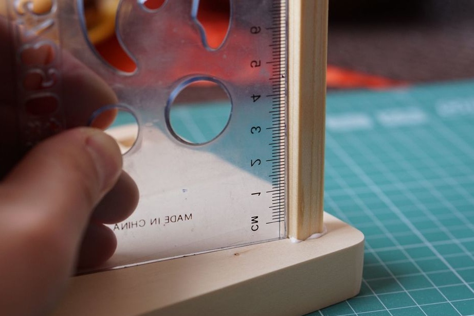
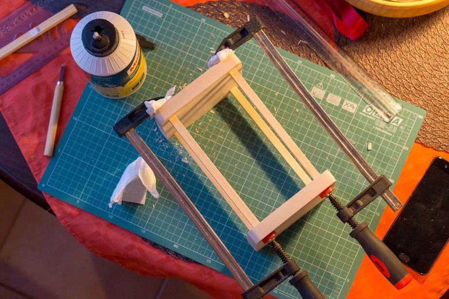
Step Four: Install Racks
Applies glue to the grooves, installs racks. Using a square aligns the racks relative to the surface.
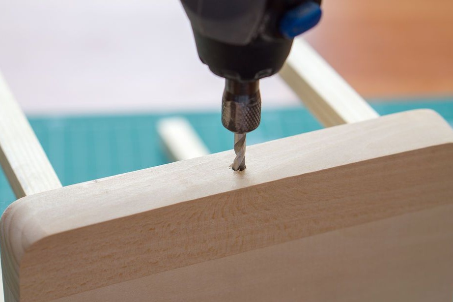
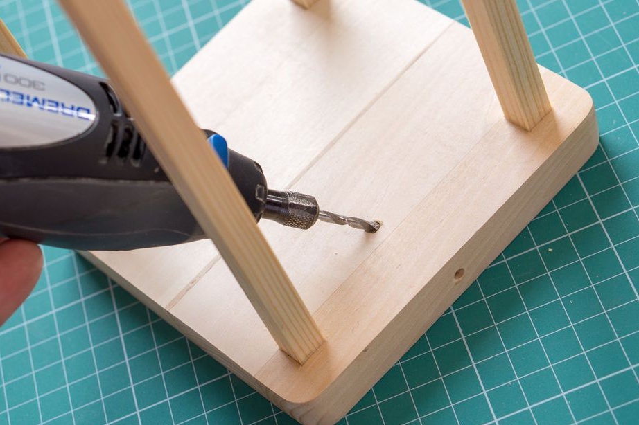
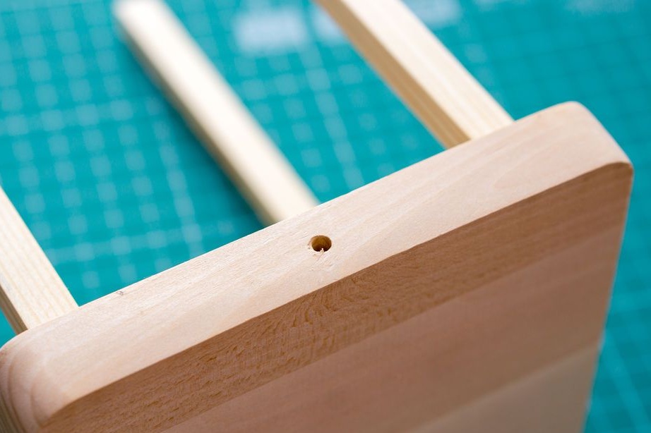
Step Five: Hole
Drills a hole for the wire.
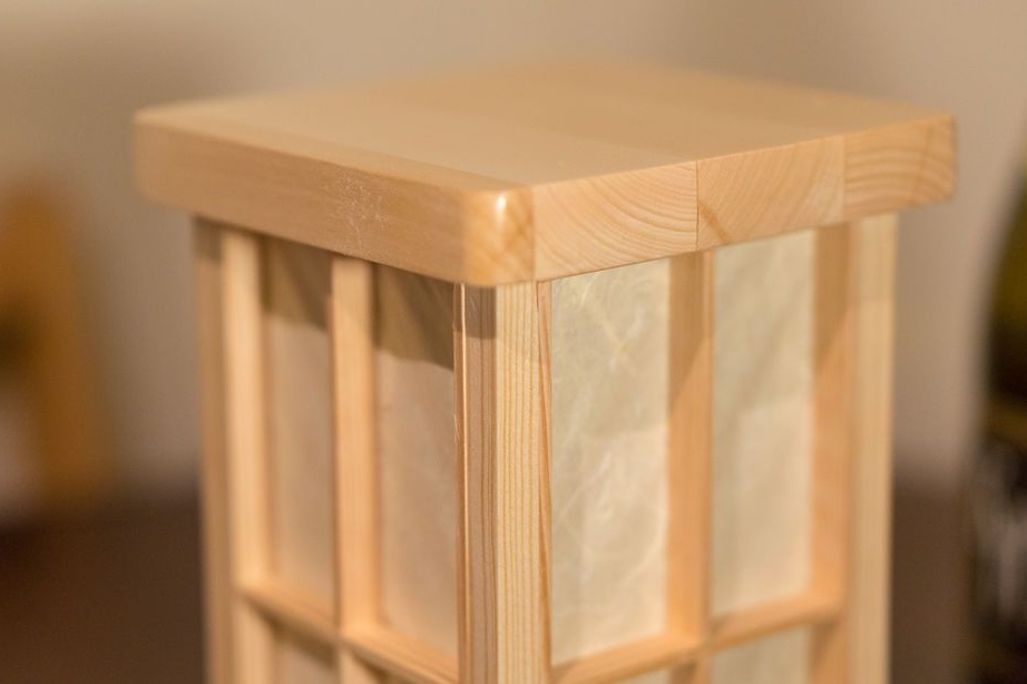
Step Six: Top
Cut grooves in the top cover. Glues the workpiece.
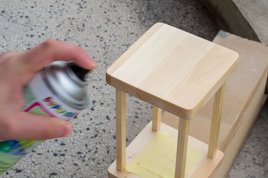
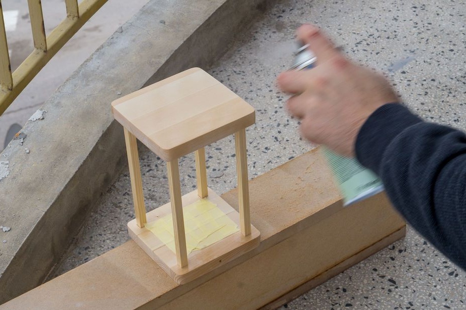
Seventh step: varnishing
The inner lower part is covered with masking tape. Apply varnish on the body in two layers.
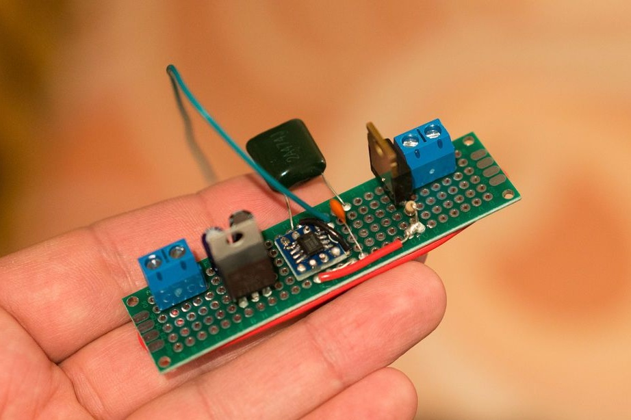
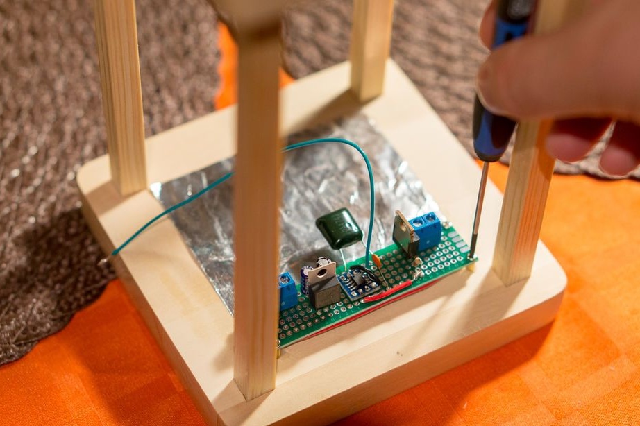
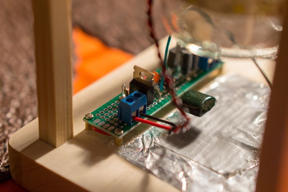
Step eight: electrical part
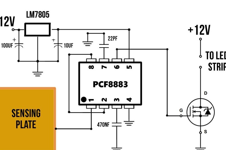
According to the scheme, mounts electrical components. For the lamp, the master uses a 12V 1A power supply.
LEDs are connected to the power source through a transistor. The latter acts as a switch - when a signal is sent to it, it passes current and turns on the light. The signal is sent by the PCF8883 chip, designed to work with touch buttons. This chip is supplied in a SOIC8 package, therefore, for its installation, you need a SOIC8 board adapter. The chip is soldered to the adapter, and then the adapter to the circuit board.
The microcircuit needs power from 3 to 9 volts, so the master mounts the LM7805 voltage regulator.
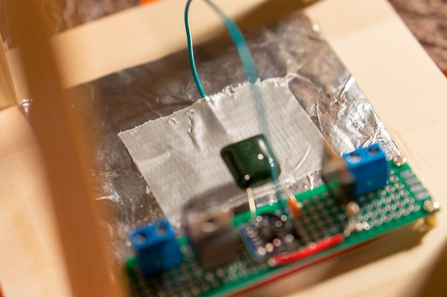
To increase the sensitivity of the touch sensor, increase the area of the touch panel or replace the 470nF capacitor with a larger one to 2500 nF.
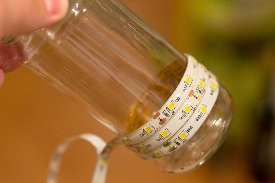
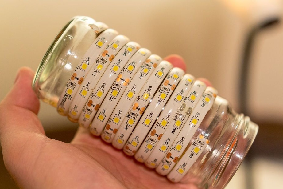
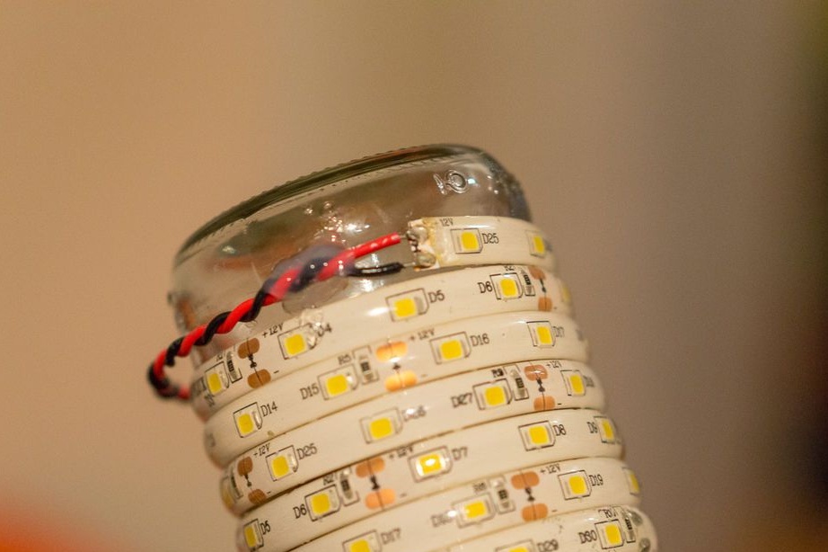
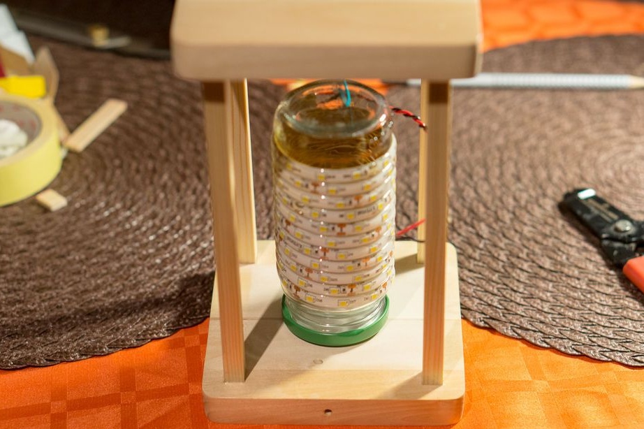
Step Nine: LED Strip
Removes the protective layer and wraps an LED strip around the can. Solder the wire. The edge of the wire is glued with two-component adhesive.
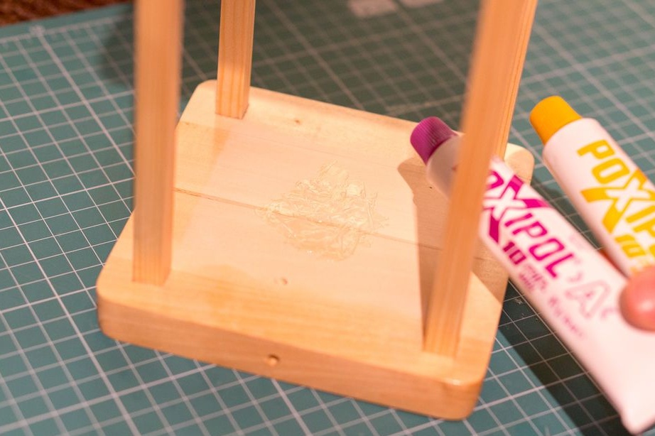
Step Ten: Sensor
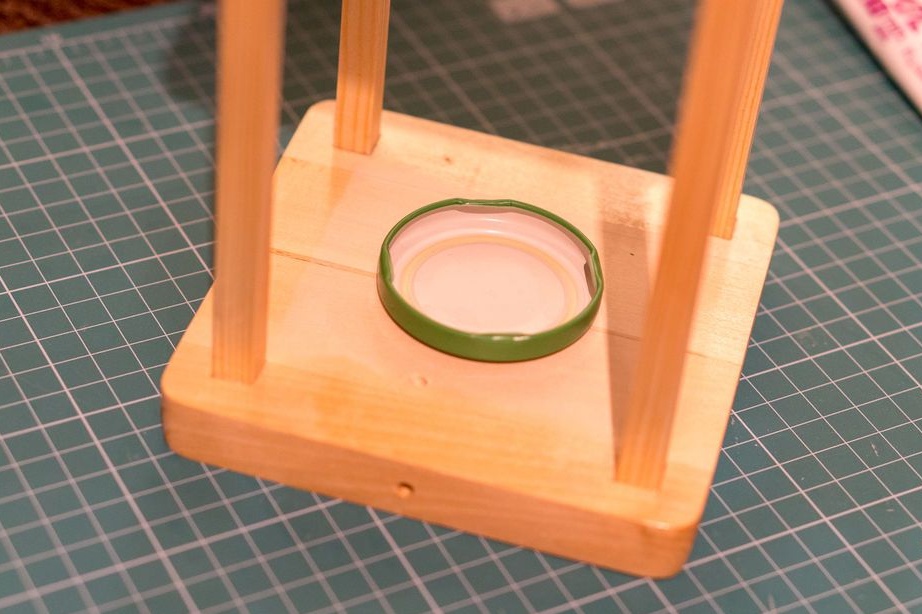
The sensor master made of foil. I cut the foil and stuck it to the inside of the top. I glued the lid of the can to the bottom.
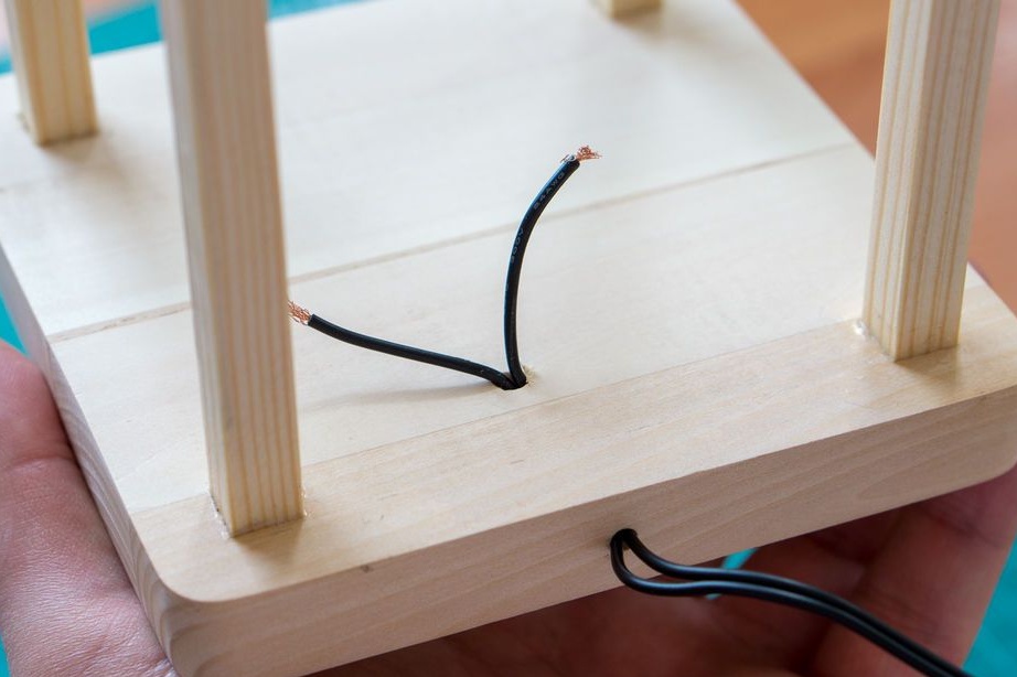
Step Eleven: Installing the Board
Screws the board. The stripped end of the blue wire is glued to the foil with masking tape. Pulls the power cord into the housing opening. Connects LED strip and board.
The PCF8883 chip has an auto-calibration function. For the circuit to work, you need to hold your hand over the touch panel (foil), from the outside.
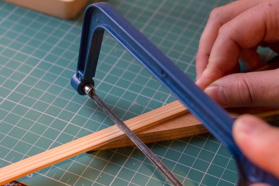
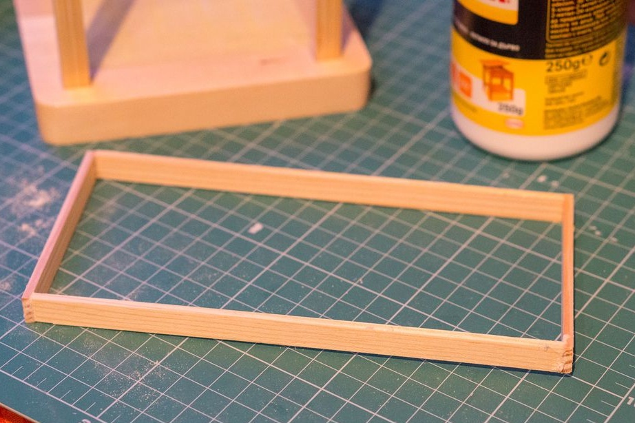
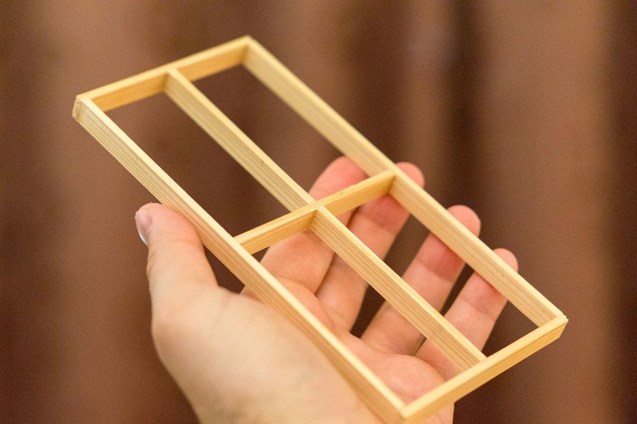
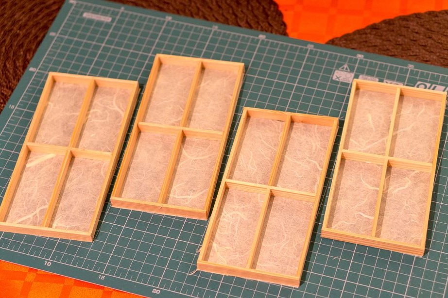
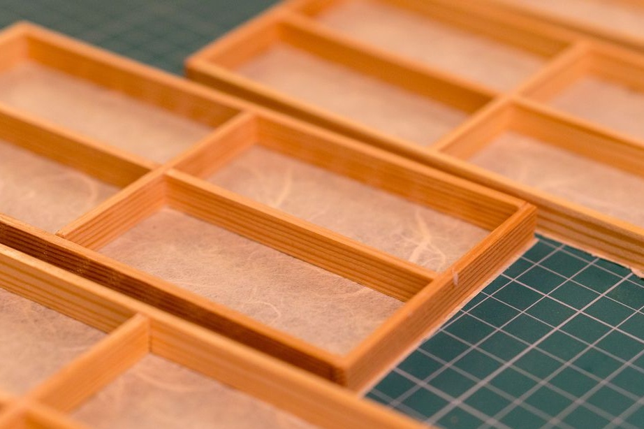
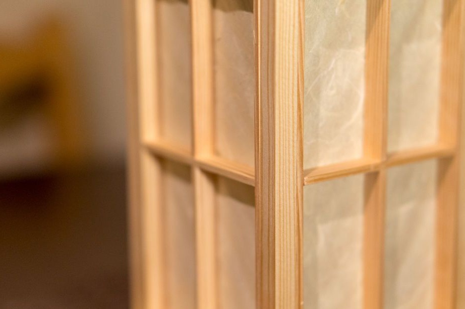
Step Twelve: The Framework
It makes frames for lamp openings from a thin rail. The frames are fixed with glue and varnished.
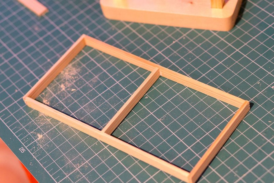
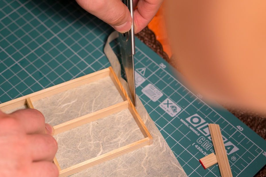
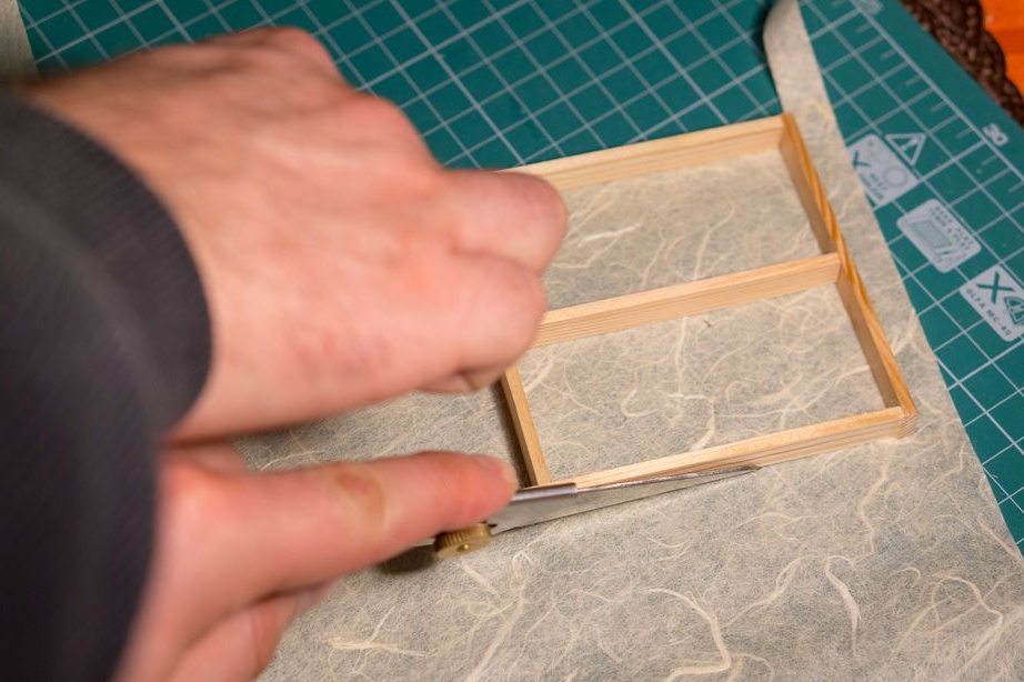
Cut and paste rice paper to frames.
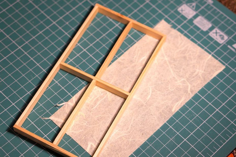
Sets frames to openings.
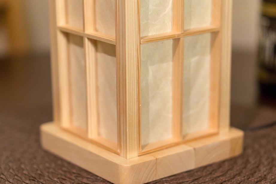
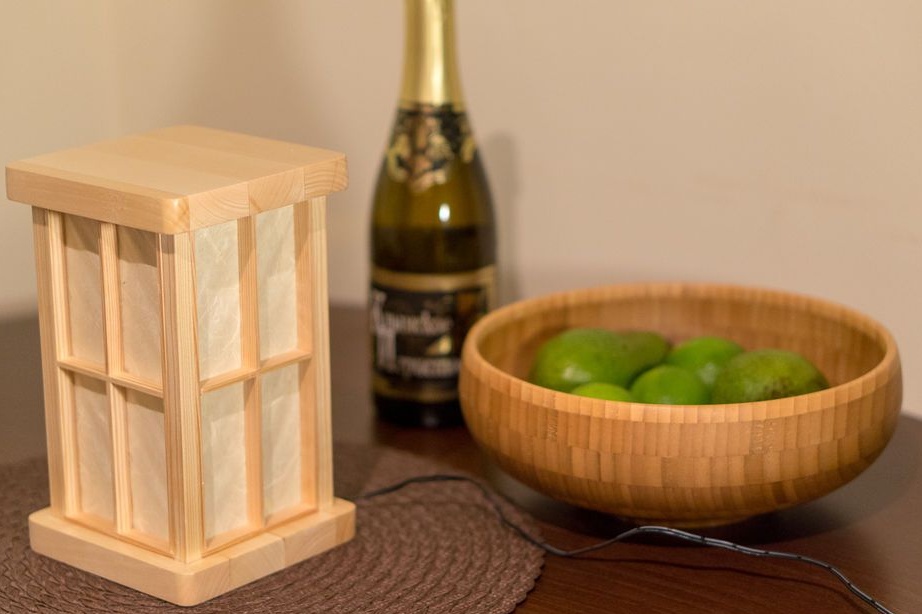
The lamp with touch control is ready.
The whole process of making the lamp can be seen in the video.