
I want to provide a simple outline metal detectorset-top boxes on one transistor. The circuit is fully operational and it will not be difficult to assemble it, but it is an ordinary oscillator circuit generator, at a frequency of about 140 KHz. There are no complex components in this metal detector, so the assembly will not take much time, in principle, as well as setting up this metal detector.
And so what we need:
- resistor R1 rated at 47 kOhm
- R2 resistor with a nominal value of 220 ohms
- C1 capacitor 0.01 uF
- capacitors C2 and C3 1000 pF
- capacitor C4 4700 pF
- C5 capacitor 47 uF at 12 v
- transistor VT1 any low-power high-frequency, reverse conductivity ... such as KT315 or KT3102 with any letter designation.
- wire of any insulated mounting or varnished with a diameter of 0.25-0.5 mm
- 9V crown or battery pack
- radio with am frequency range
Now let's move on to the manufacture itself:
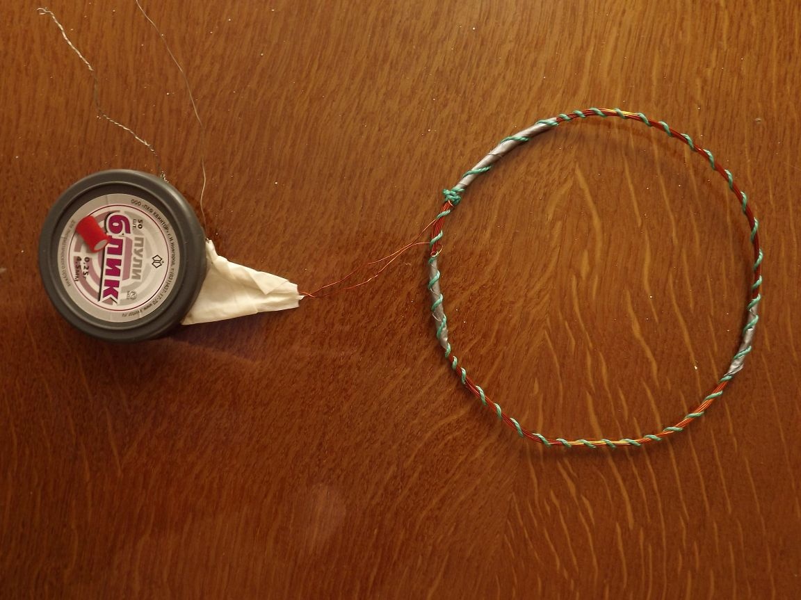
Step 1: Coil For the coil, you can use any insulated or varnished wire whose diameter should be in the range of 0.25-0.5 mm. The coil itself must be 12 cm in diameter, you can make a template for winding it yourself, or choose an object with a suitable diameter and wrap it. The number of turns should be 16. The coil is convenient to manufacture, no bends from the middle, all the more so, and the number of turns is not large.
Step 2: assembly of the circuit. here is the diagram itself:
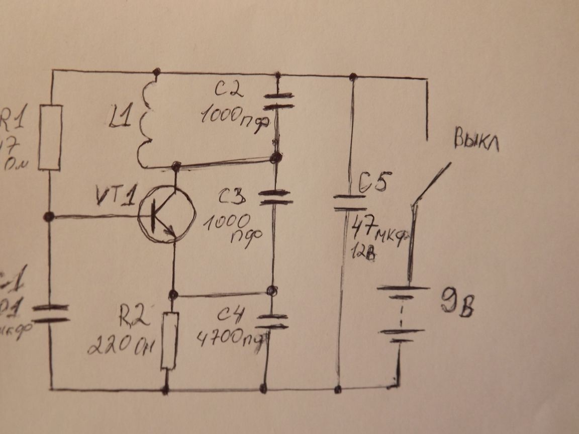
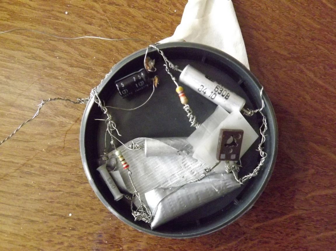
Resistors and capacitors can be of any type, this will not particularly affect the operation of the circuit and it will work in normal mode. A transistor, as they say, is suitable for any low-power high-frequency, reverse conductivity. For example, KT315 or KT3102 with any letter designation, as well as their analogues. As analogs, you can use the BC847B bipolar transistor - this transistor has the advantage that it does not fail so quickly when soldering and soldering; another one is 2SC634; and another 2SC641, in more detail about them if anyone is interested I will describe below. The circuit itself can be assembled on a board made of getinaks or textolite, it does not matter, and printed wiring is not required. For example, I did the installation by mounting, the connections are not neat of course, and I’ll do it more temporarily, I’ll need to replace the capacitors, which are 1000 pF but they are 630 V, but still the circuit works well. do not repeat connections like me
 better do everything right away with insulated wires
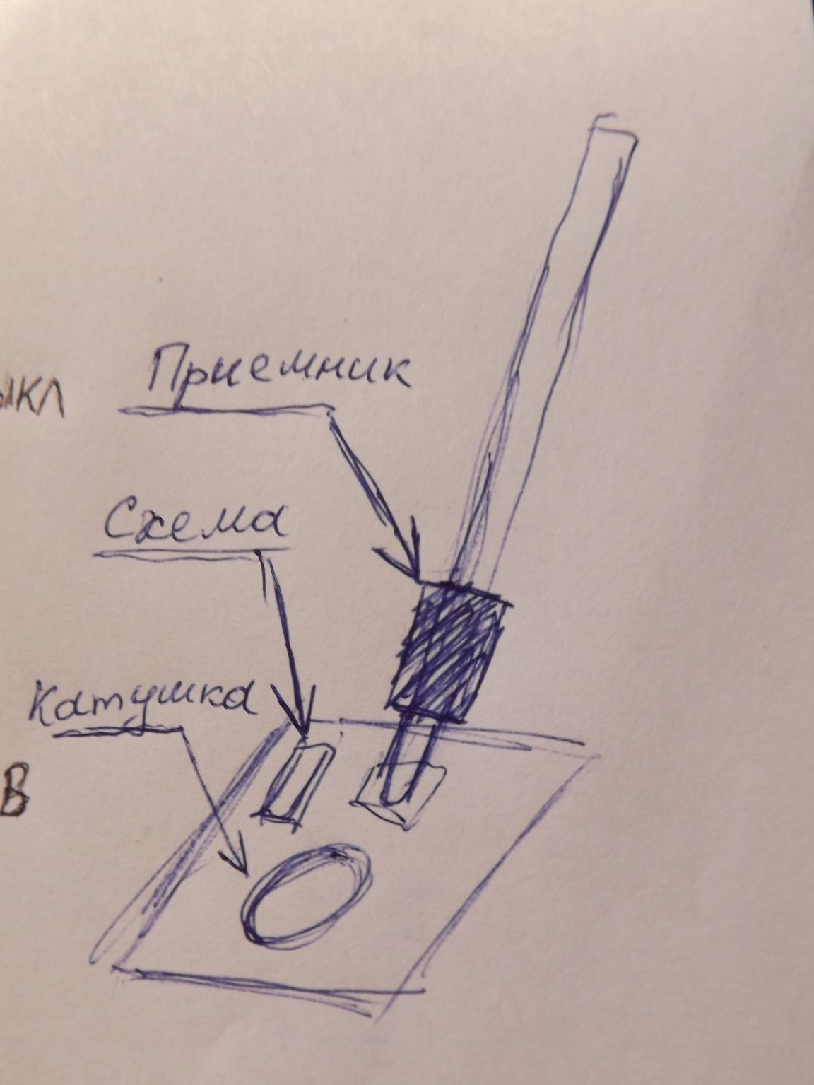
Step 3: assembly and tuning of the metal detector. On a flat surface, such as plywood, we place a coil with a circuit and power.We mount a radio receiver on the handle in close proximity to the circuit, this is necessary for good communication with the oscillator circuit generator. here is a sample diagram:
The setting is as follows: we turn on the power of the circuit, now turn on the radio and transfer it to the frequency range, adjust to a frequency close to 140 KHz, since it is at this frequency that our oscillator circuit generator works, as a result, a sound resembling a creak should be heard. When the coil passes near metal objects, the tonality will change and this will be clearly audible. In addition to ferrous metal, this metal detector detects non-ferrous metal in particular. He can detect objects such as rings and coins at a depth of up to 20 cm. Well, of course, depending on the size of the coins.
As you can see, the scheme is not complicated, there are few details, I won’t repeat even as clumsily as I did, but it will work, it’s a 100% guarantee.
P.S. KT315 analogues
As promised at the end, a few words about the analogs of the KT315 transistor.
Bipolar Transistor BC847B
Low power transistor with significant gain. Maximum power dissipation - 0.25. Up to 50 volts can be supplied to the collector-base direction. Up to 45 volts per collector-emitter. The maximum voltage for the emitter-base direction is 6 volts. The collector junction has a capacity of 8. The limiting temperature of the junction is 150 degrees. The statistical current transfer coefficient is 200.
Bipolar Transistor 2SC634
The maximum power dissipation is 0.18. The maximum allowable voltage to the collector base and collector-emitter is 40 volts. The emitter base is only 6 volts. The collector junction capacity is 8. The limiting junction temperature is 125 degrees. The static current transfer coefficient is 90.
Bipolar Transistor 2SC641
Maximum power dissipation - 0.1. The voltage in the direction of the collector - base should not exceed 40 volts. The maximum voltage in the collector - emitter direction should not be more than 15 volts. For the emitter - base direction, this value should not exceed 5 volts. The collector junction capacity is 6 units. The maximum temperature of the transition is 125 degrees. The static current transfer coefficient is 35.
You can read more about analogues here
Good luck to everyone in the assembly and in the search!
