» Topics » DIY ideas »Turning on the remote control load from the TV

Turning on the remote control load from the TV


Hello everyone. It is not always possible to conduct wiring to the lamp and equip it with a full-fledged switch. Here comes to the rescue electronics.
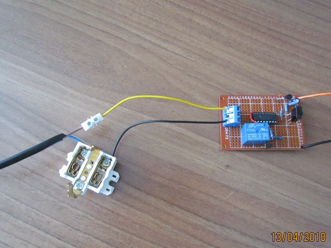
The scheme is simple

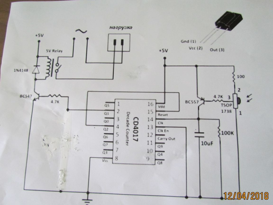
Turning on appliances using the remote control. Here, the infrared signal serves as a mediator between the photodetector and emitter, which controls the circuit for switching on a specific load. This is a popular device today, very convenient to use, especially for the Lazy. One of these devices I bring to your attention. The core of this scheme is a decimal counter with a CD4017 decoder. The infrared signal is received by a TSOP1738 photodetector operating at a frequency of 38 kHz.


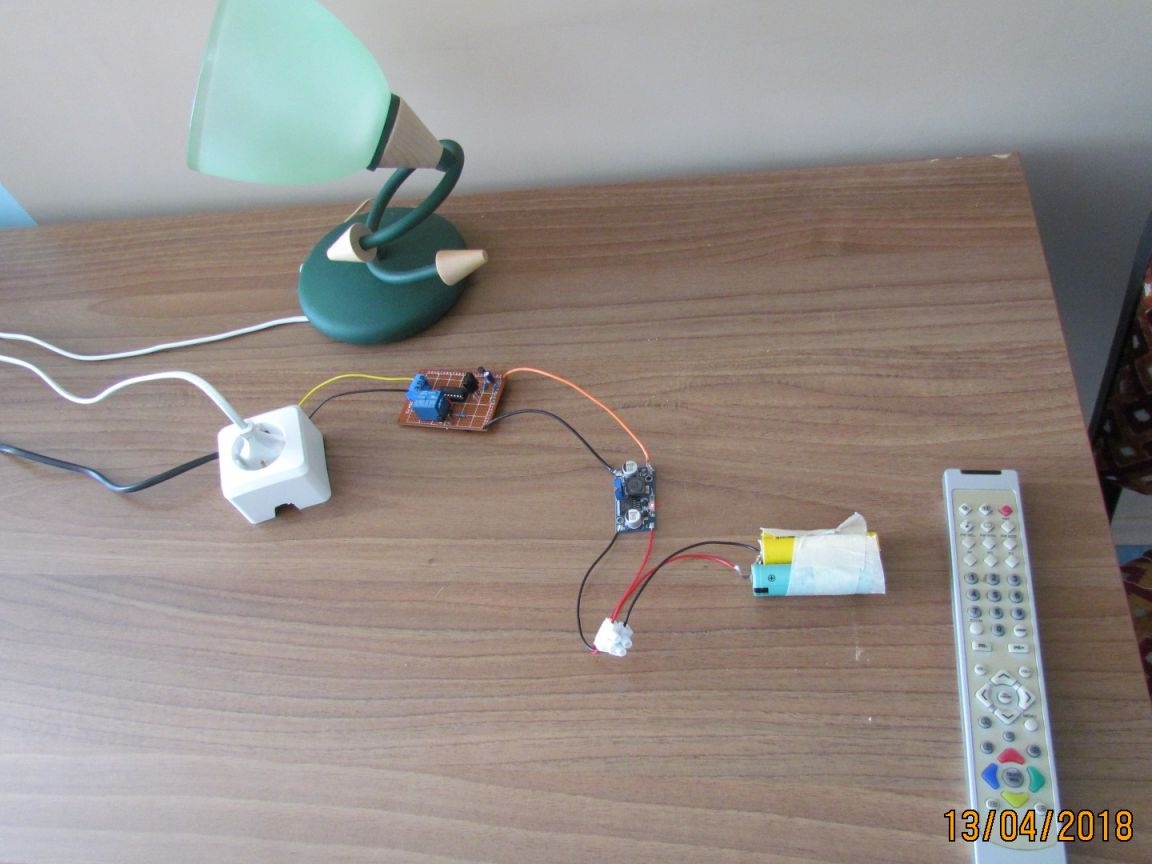
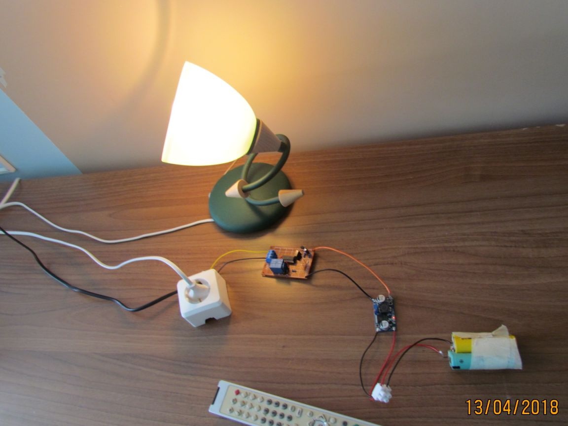
The relay here I applied 5 volts. The device works from any remote control. Sunlight does not interfere .. covered the board with a shoe box .. the relay also works but not so clearly.

A properly assembled device does not need to be set up and starts working immediately. Power supply 5 is necessarily stabilized. The relay can withstand a load of 10 amperes.
Thank you all for your attention.
Question \ topic is automatically published in the social. site network - stay tuned for answers there:

Suitable for topic

Related topics

Add a comment

    • smilesmilesxaxaokdontknowyahoonea
      bossscratchfoolyesyes-yesaggressivesecret
      sorrydancedance2dance3pardonhelpdrinks
      stopfriendsgoodgoodgoodwhistleswoontongue
      smokeclappingcraydeclarederisivedon-t_mentiondownload
      heatirefullaugh1mdameetingmoskingnegative
      not_ipopcornpunishreadscarescaressearch
      tauntthank_youthisto_clueumnikacuteagree
      badbeeeblack_eyeblum3blushboastboredom
      censoredpleasantrysecret2threatenvictoryyusun_bespectacled
      shokrespektlolprevedwelcomekrutoyya_za
      ya_dobryihelperne_huliganne_othodifludbanclose
6 comments
"especially for the Lazy" - the author himself does not belong to them. He has the same "Record 6" with PTK.
and this ... any click is accepted after all, and not just the special "on / off"?
Here, the counter (though drawn through ... uh ... one place) is used as a counting trigger, nothing criminal, but in the absence of such a D-trigger can be used.
And to improve performance, you can, as rightly noted Pronin, in the gap between the collector and the input of the IC include TS, for example, K561TL1. Yes, and I would drag the filter from the collector to the base circuit.
Such a thing is best done on a Schmitt comparator or trigger, Imho.
Quote: Ivan_Pokhmelev
An electrolyte at the clock input of a CMOS chip is not a good idea, and even with its inclusion in the collector of the transistor and limiting the charging current due to a change in the base current of the transistor.

Well, what do you recommend? How to change the circuit for the better (make it more reliable)?
Tell me please. I was interested in this homemade product.
I think that even the smallest member of the site can repeat such home-made work.
Kudeyaru - respect, well done Kudeyar. I love such homemade products. With every post you grow in my eyes.
An electrolyte at the clock input of a CMOS chip is not a good idea, and even with its inclusion in the collector of the transistor and limiting the charging current due to a change in the base current of the transistor.

We advise you to read:

Hand it for the smartphone ...