
Hello to all lovers homemade. In this article I will tell you how to make a power supply with adjustable current and voltage on encoders do it yourself, in the assembly of which the kit kit will help, a link to it is at the end of the article. Such a radio designer will be useful to anyone who wants to try their hand at radio electronics, especially beginner hams. Also, this power supply can be used in various other homemade products or make a separate laboratory power supply for testing other circuits and so on.
Before you start reading the article, I suggest watching a video with a detailed process of assembling this kit kit, as well as a small check.
In order to make a power supply unit with adjustable current and voltage on the encoders with your own hands, you will need:
* Kit
* Soldering iron, solder with flux
* Silicone soldering mat
* Device for soldering "third hand"
* Side cutters
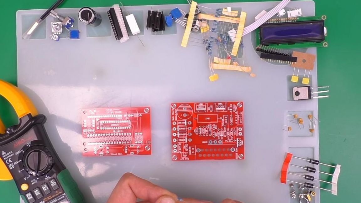
* Multimeter
* Drill
* Screwdriver with a drill
* Aluminum radiator
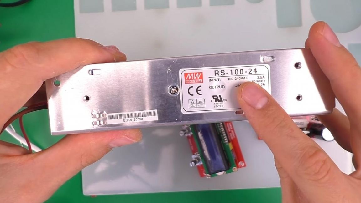
* Power supply with voltage up to 30V
Step one.
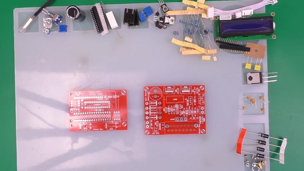
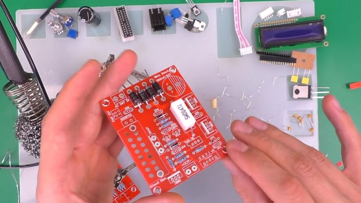
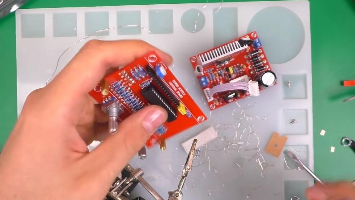
First, consider the kit kit, there are two double-sided printed circuit boards with all markings, which is very convenient, since it does not require additional assembly instructions, the holes for the radio parts are metallized, and the overall quality of the boards is high.
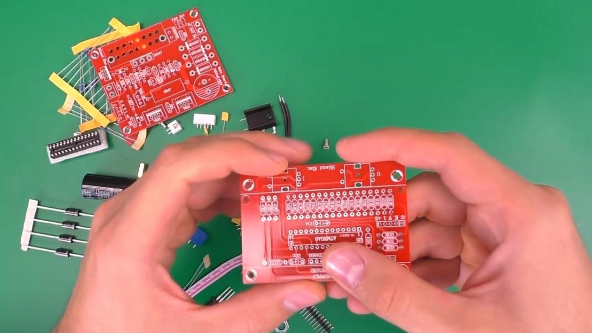
There is also a chip with a socket under it and other components, for example, resistors, diodes and capacitors, both ceramic and one electrolytic.
Unlike other circuits of power supplies, here the encoders act as current and voltage controls, and a display is provided for information output.
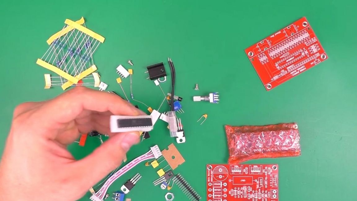
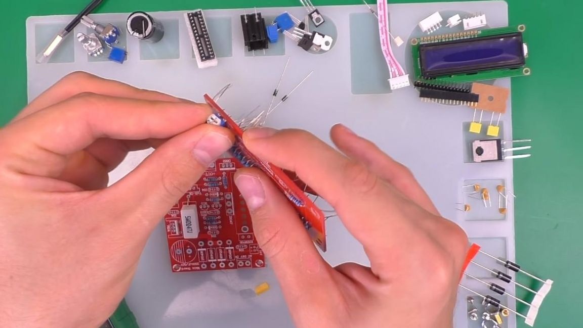
Next, we lay out all the details on a silicone soldering mat, so nothing will be lost and will always be at hand, and then proceed to the assembly itself.
Step Two
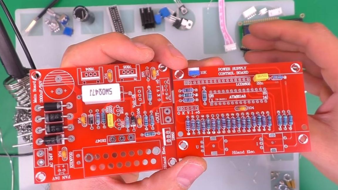
We begin the assembly of the circuit with those parts, which are in more numbers, namely resistors. The resistors from the kit are pre-fastened with a piece of paper so as not to determine the resistance of all individually, but only one of the bundles.
You can determine the resistance of resistors in several ways, for example, with a multimeter, this method is the fastest and easiest.You can also find out the value by the color bars on the resistor itself and the reference table, or using the online calculator. After determining the resistance, we install the resistors on the board, according to the ratings indicated on it, on the back side we bend the leads so that the radio components do not fall out when soldering. We do the same with the second board, since it also has a place for installing resistors.
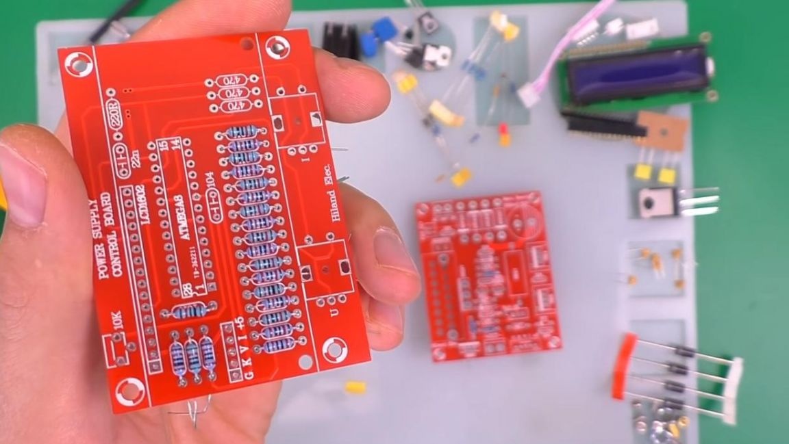
Next, we install a powerful 5-watt resistor on the board, and on the other board we insert a tuning resistor of 10 kOhm, which is useful for adjusting the brightness of the display.
Step Three
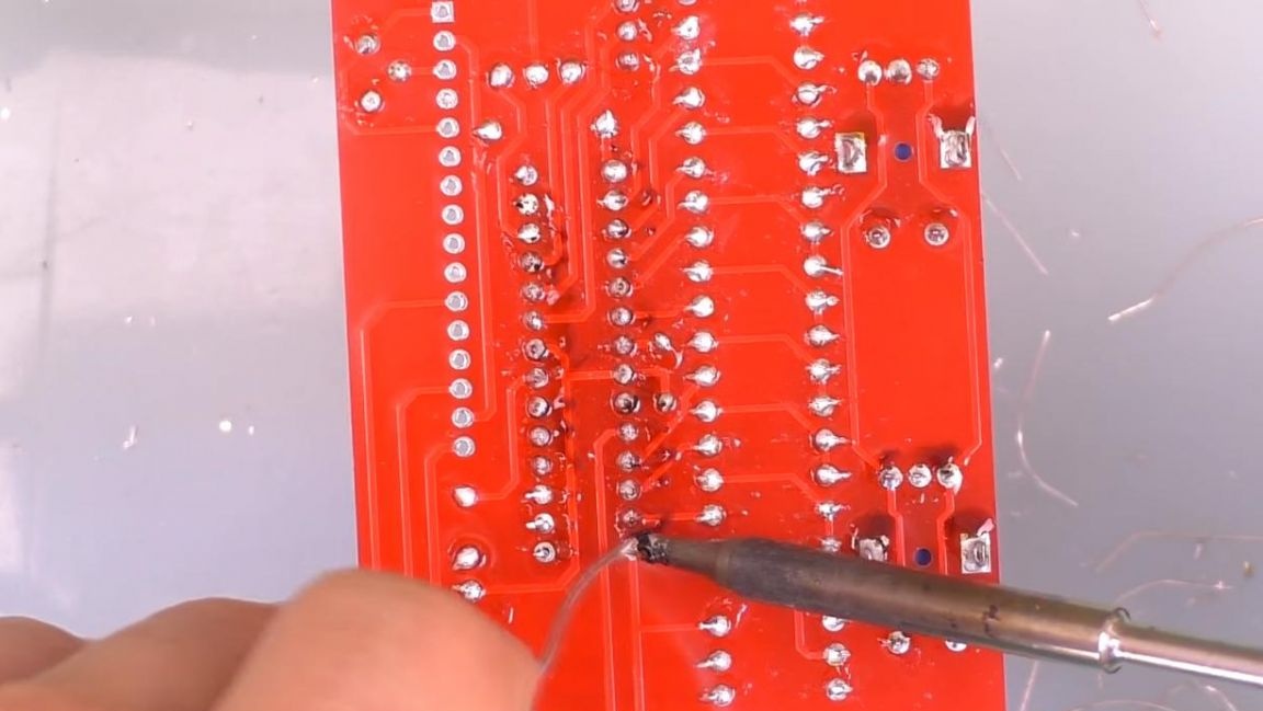
Now you need to solder the radio elements. We fix the board in the soldering device "third hand" and begin to solder the conclusions to the contacts using a soldering iron and solder, which already contains the flux.
We do the same with the second board.
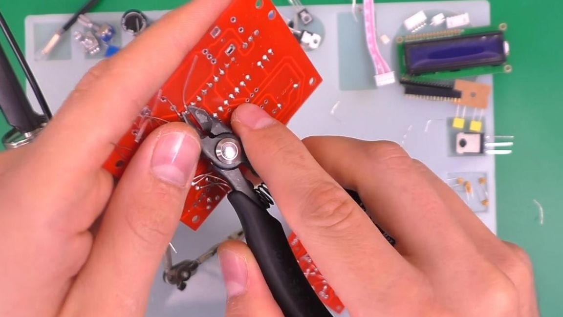
After soldering the parts, we remove the extra parts of the conclusions with the help of side cutters. When removing pins with side cutters, be careful as you can tear the track off the board.
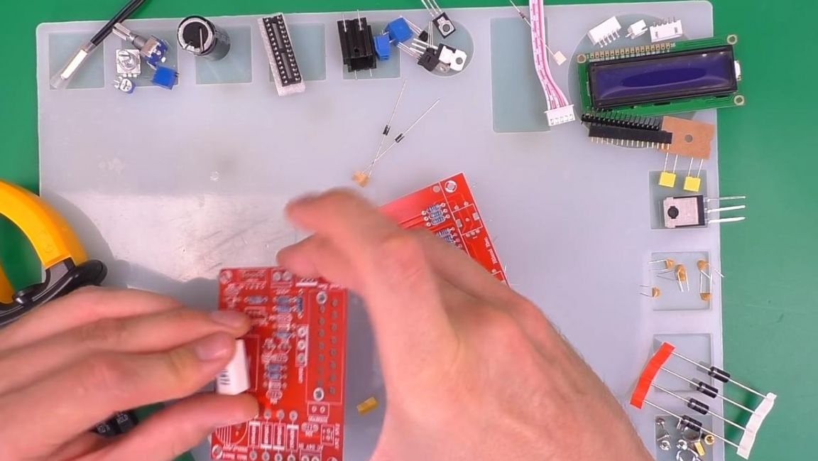
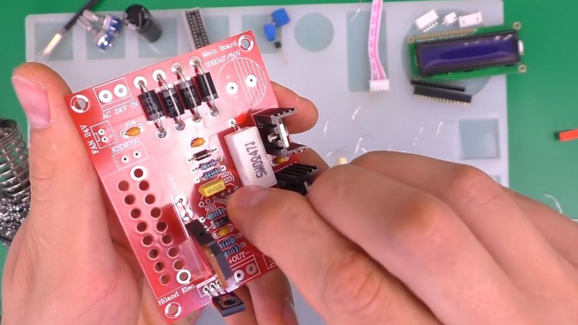
Then we install the diodes, we are guided by the strip on their case and the marking of the board.
Next, we put ceramic non-polar capacitors, their marking is also signed, and after that we insert the multi-turn trimming resistor.
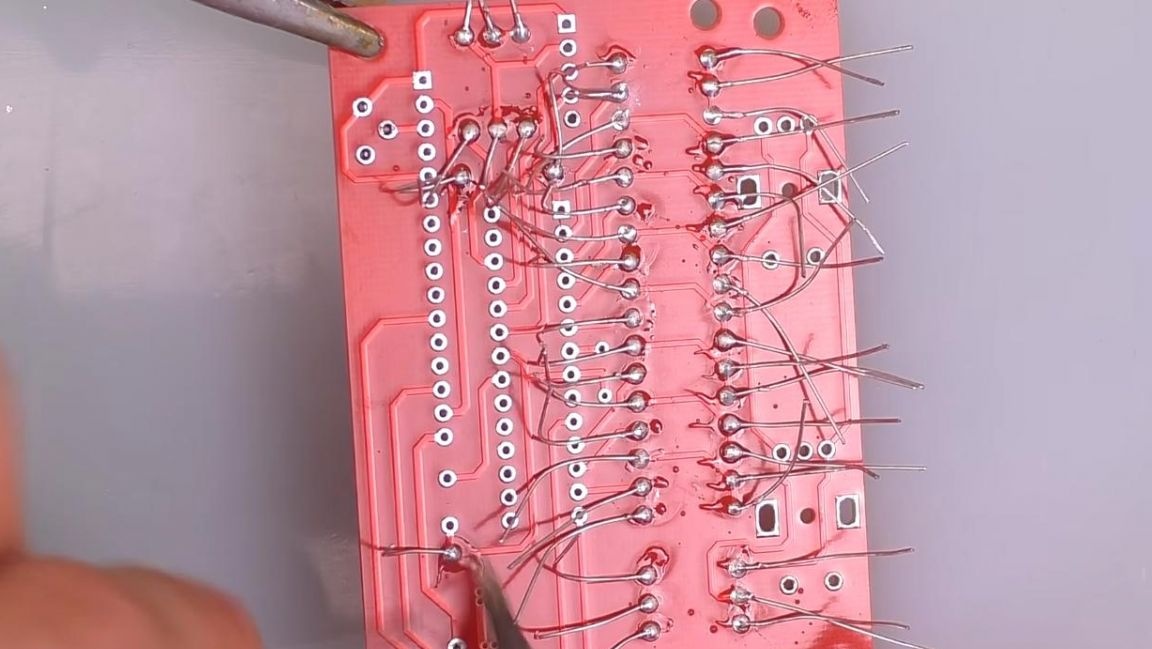
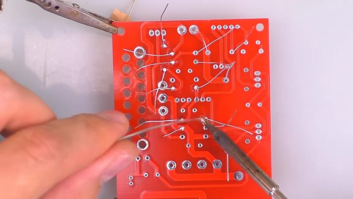
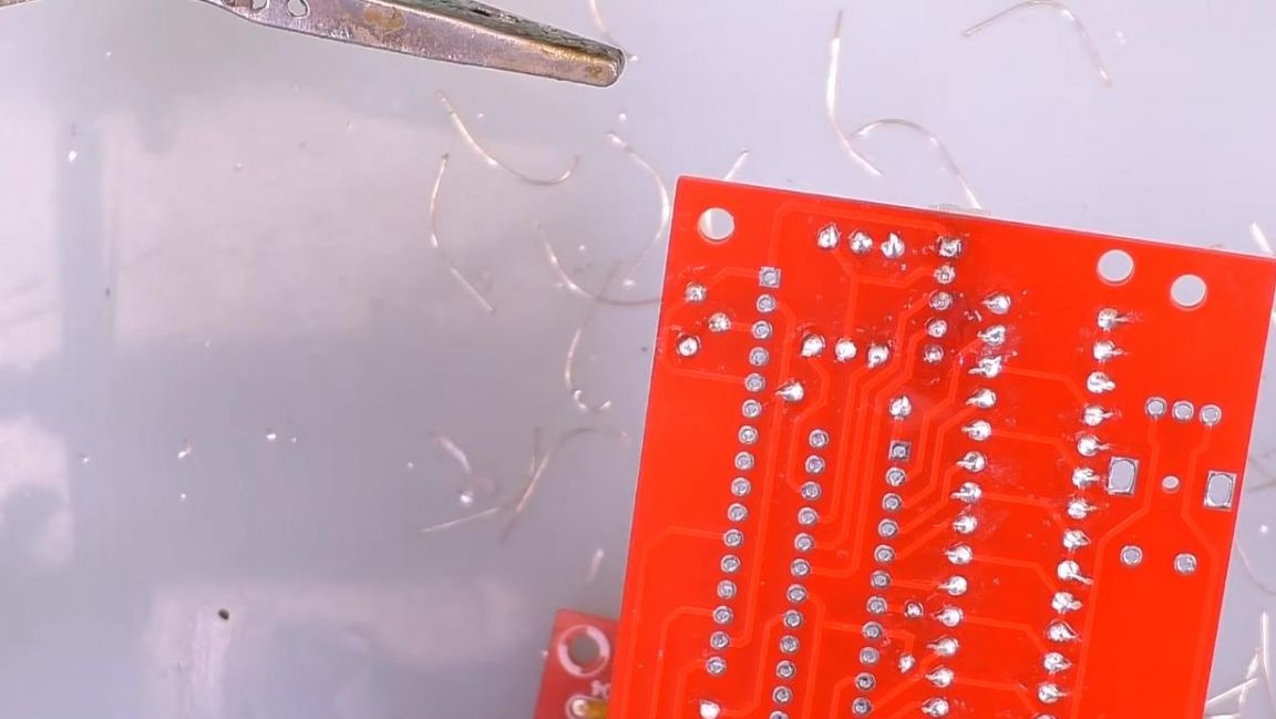
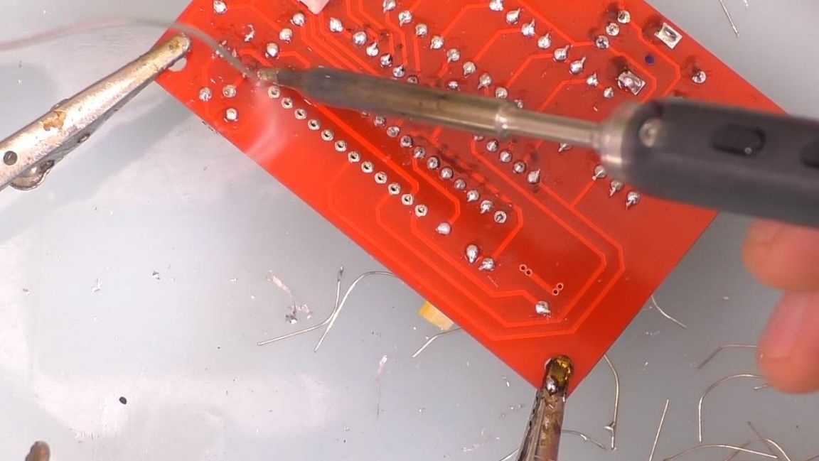
Having fixed the board in the "third hand", solder the radio components, then pull it out and solder the elements on the second board.
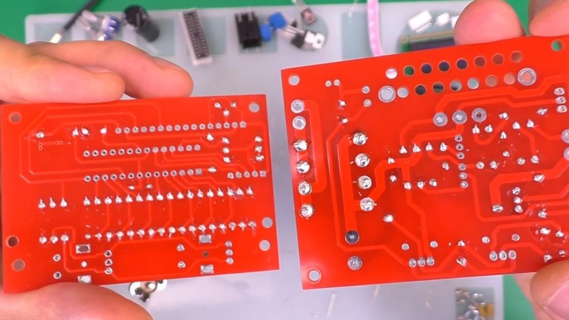
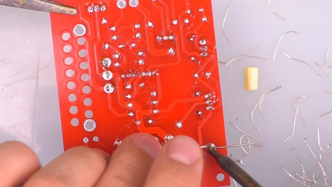
As a result, the two boards on the reverse side look like this.
Step Four
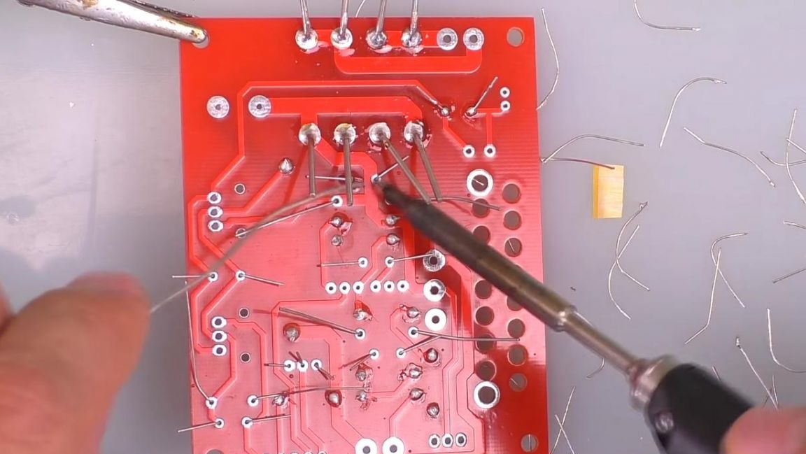
The time has come to install transistors, their places are signed on the board, and the position of their metal part must coincide with the direction of the thick line on the marking.
Two smaller transistors are pre-installed on the radiators and also inserted into the holes on the board.
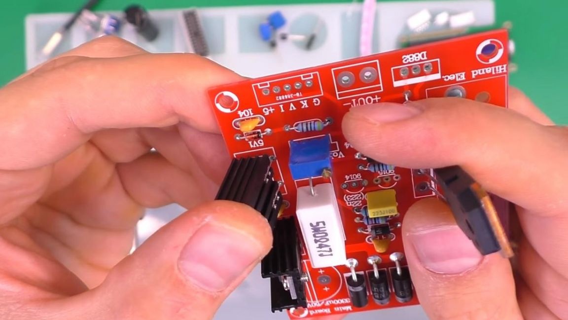
We insert the smallest transistors according to the shape of the case, which is also shown on the board.
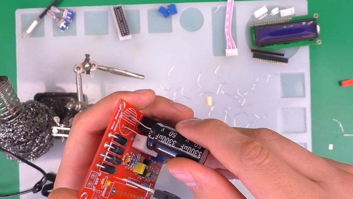
We mount the electrolytic capacitor observing the polarity, the long leg is a plus, short-minus, on the board the minus is indicated by a shaded semicircle.
We fix the "third hand" in the soldering device and solder the terminals of the components. The excess parts of the legs are removed with side cutters.
Step Five
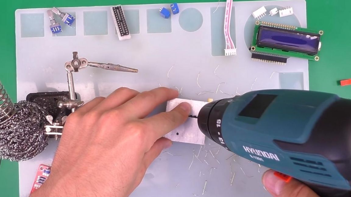
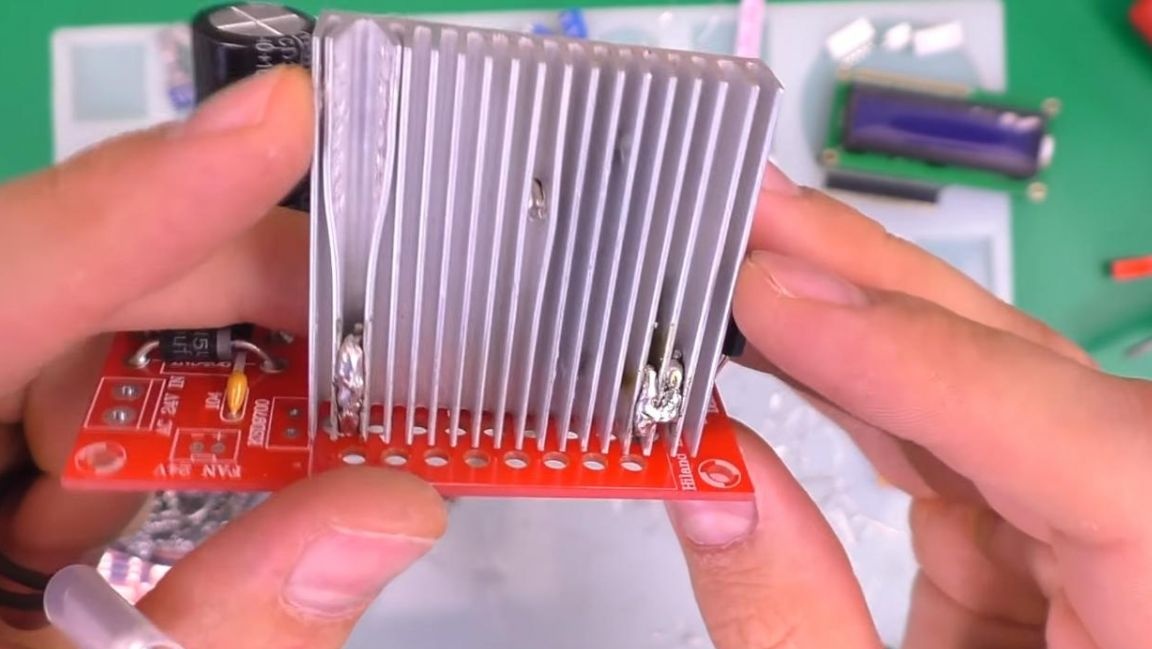
For a large transistor, additional cooling in the form of a radiator is necessary, we find a suitable one and drill a hole in it slightly less than the diameter of the screw.
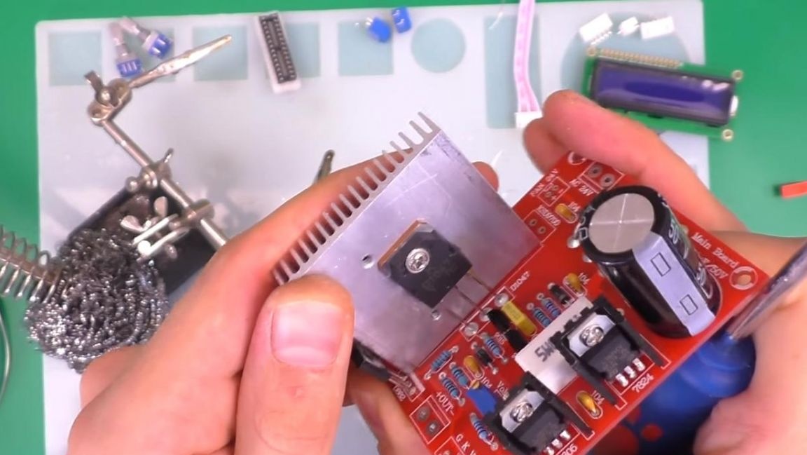
Then we fasten the transistor to the radiator, it is advisable to apply thermal grease for better heat transfer.
For better fastening of the radiator, you can solder the remains of the conclusions from the diodes and then apply solder to them.
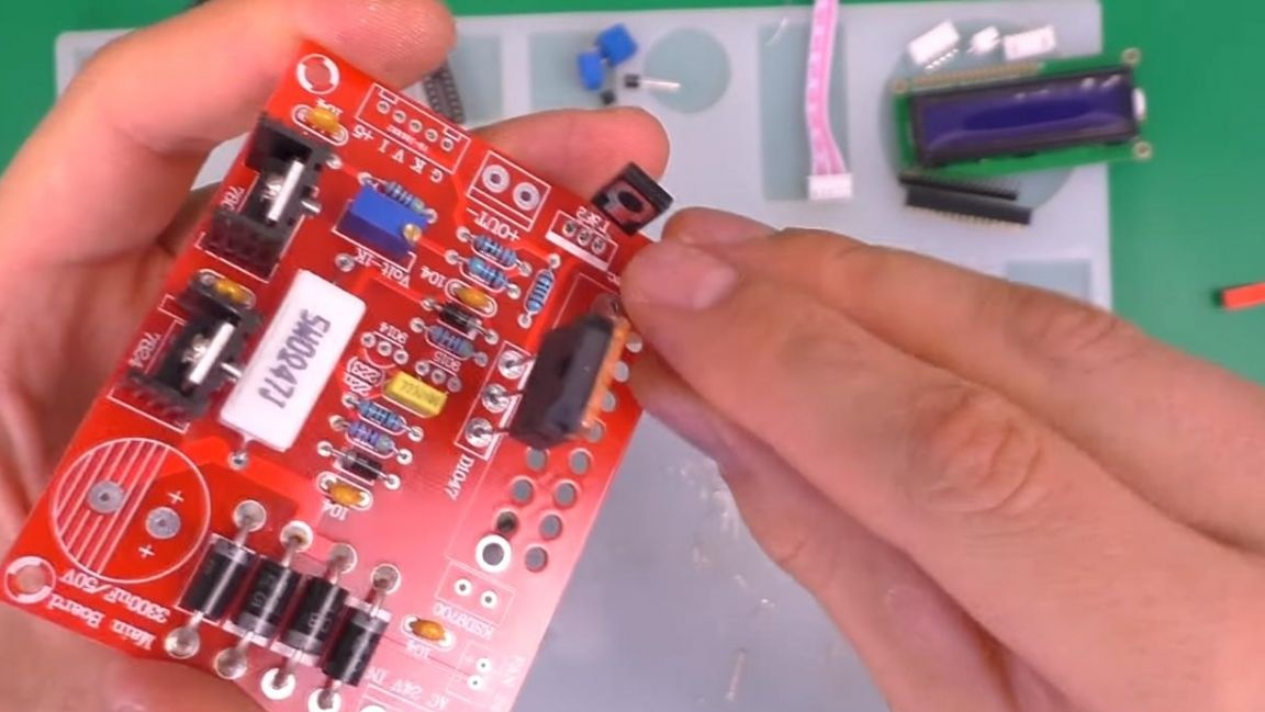
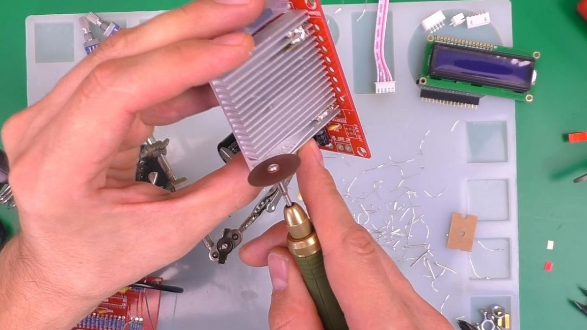
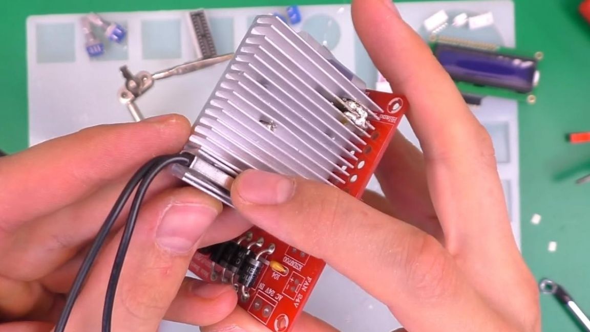
The power supply circuit contains overheating protection, so we install the thermostat from the kit between the fins of the radiator, expanding them with pliers and drilling a groove with a drill, then solder its wires to the board.
Step Six
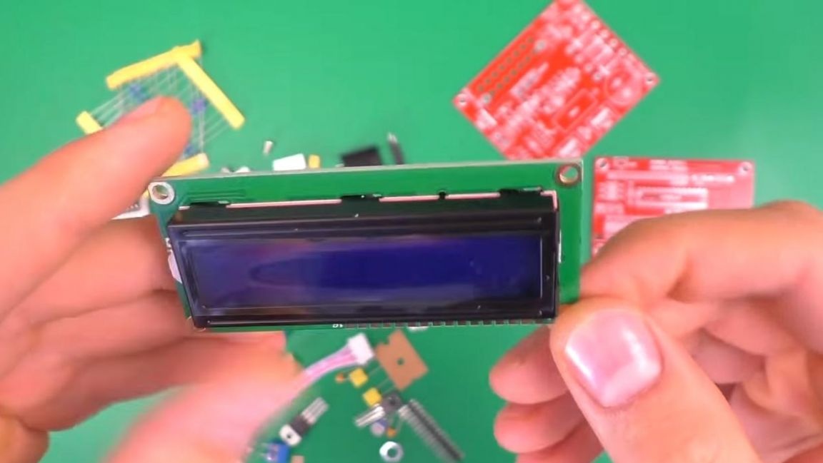
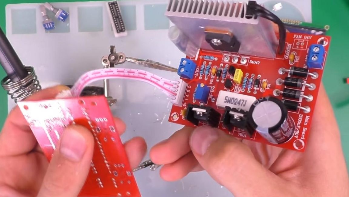
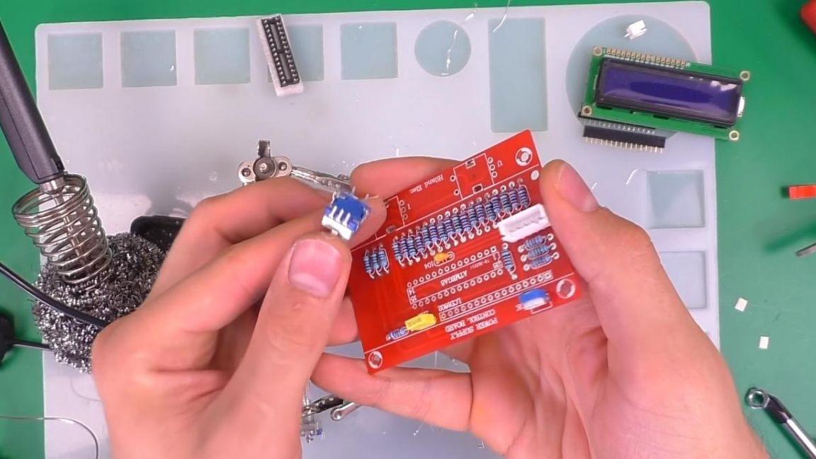
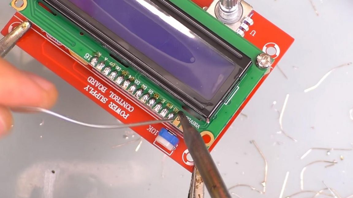
There is a special loop for connecting encoders and the display, the connectors for it must be soldered to both boards, do not mix up their position during installation.As it turned out, the connector was soldered on the wrong side, so try on the display before soldering.
We install encoders on the board, it will not work to make a mistake here, since on the one hand it has two contacts, on the other three.
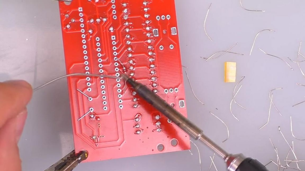
Then we insert the socket under the microcircuit, being guided by the key in the form of a recess on the case and the board, and sealed everything from the back.
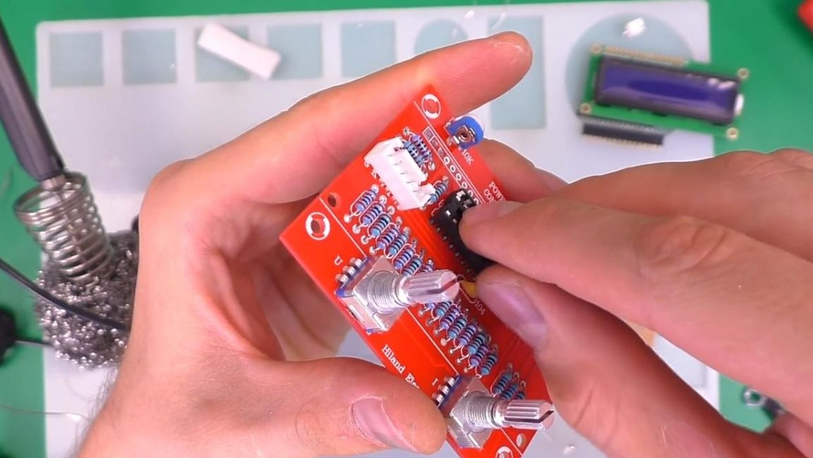
Next, we solder the contacts to the display, as well as the contacts on the board itself, after which we disconnect the connector and install the chip in place, focusing on the key. Installing the microcircuit at the last moment is accompanied by the fact that when soldering the board with the microcircuit already inserted, it can damage it by static electricity.
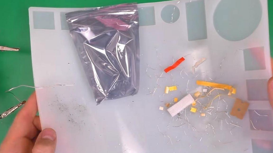
After soldering on the silicone mat, there are quite a lot of scraps from the legs of the radio components, so it is very convenient to use it, since it is not necessary to collect garbage after work, but just take the mat and pour all the waste from it into the garbage.
Seventh step.
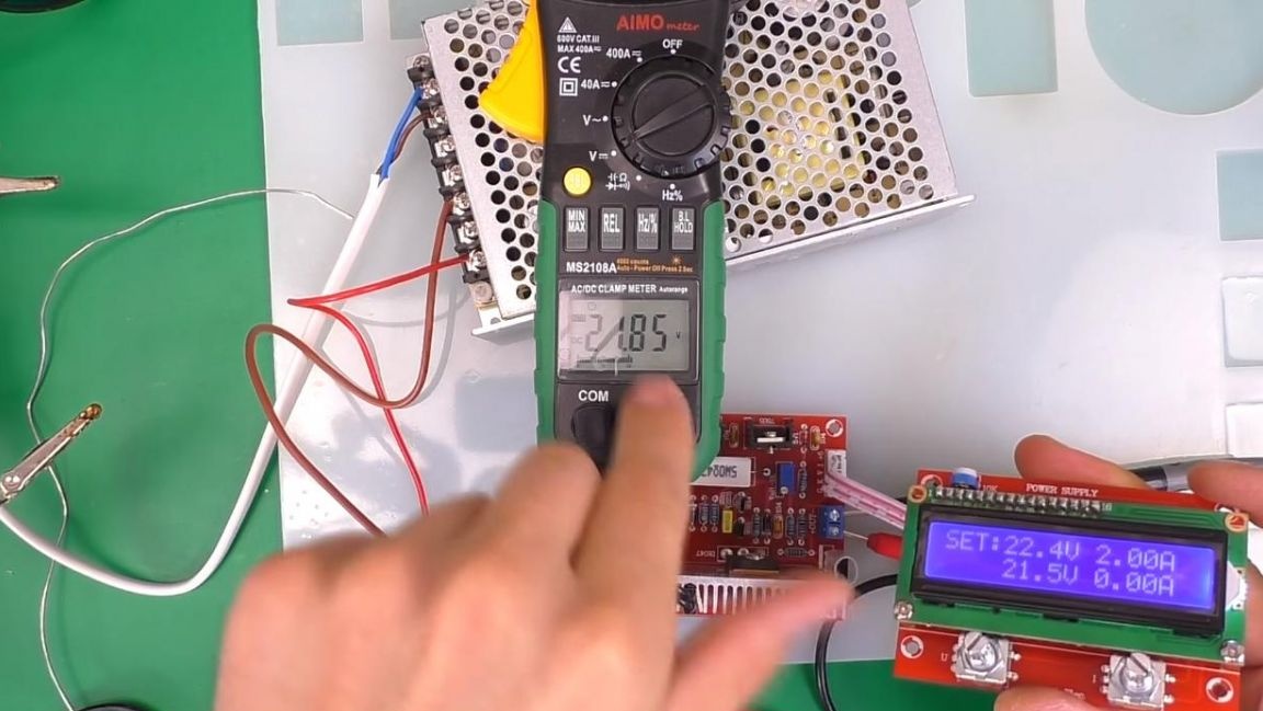
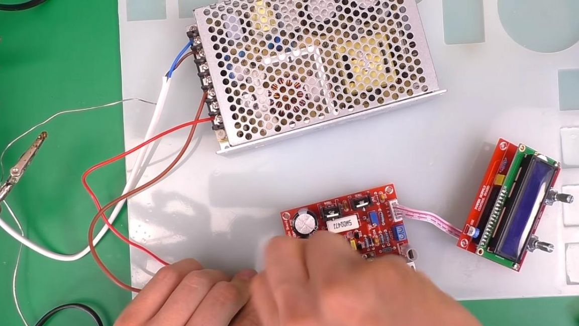
At this stage, the kit is ready, now you can test it. We connect the power supply voltage up to 30 V, the circuit contains protection against reverse polarity.
Next, we adjust the brightness of the display, for this we twist a variable resistor before a clear image appears.
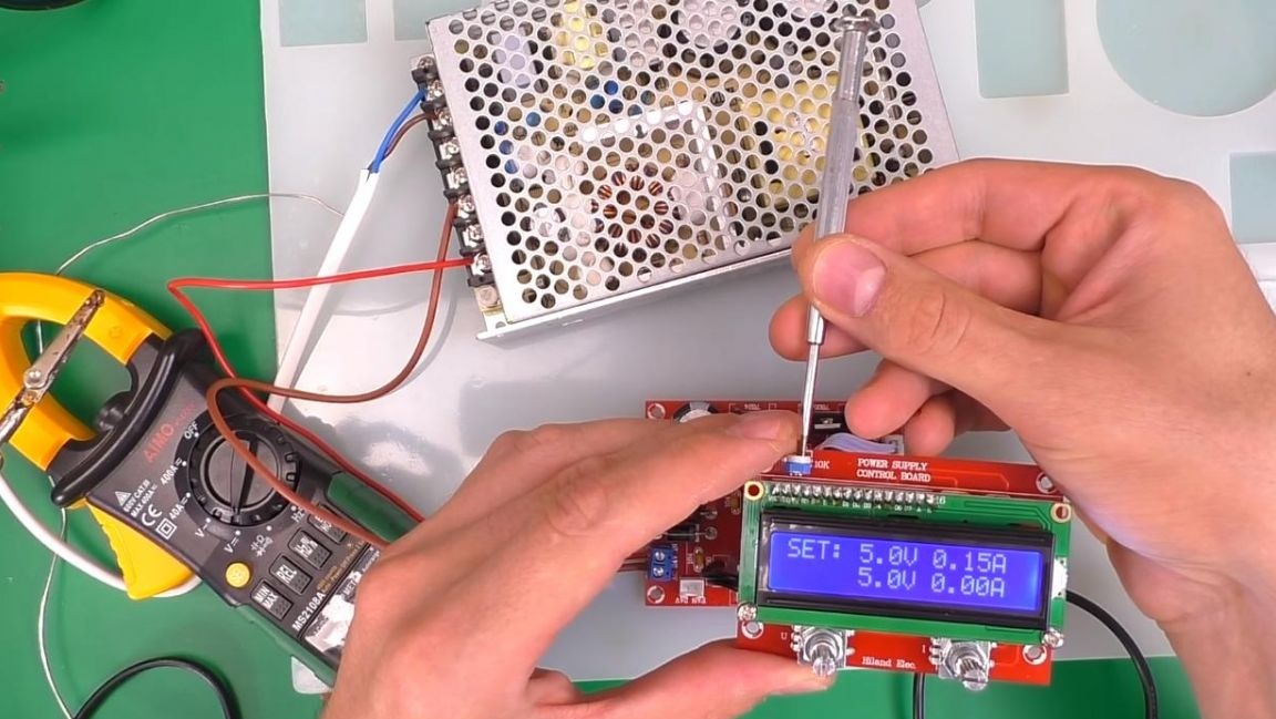
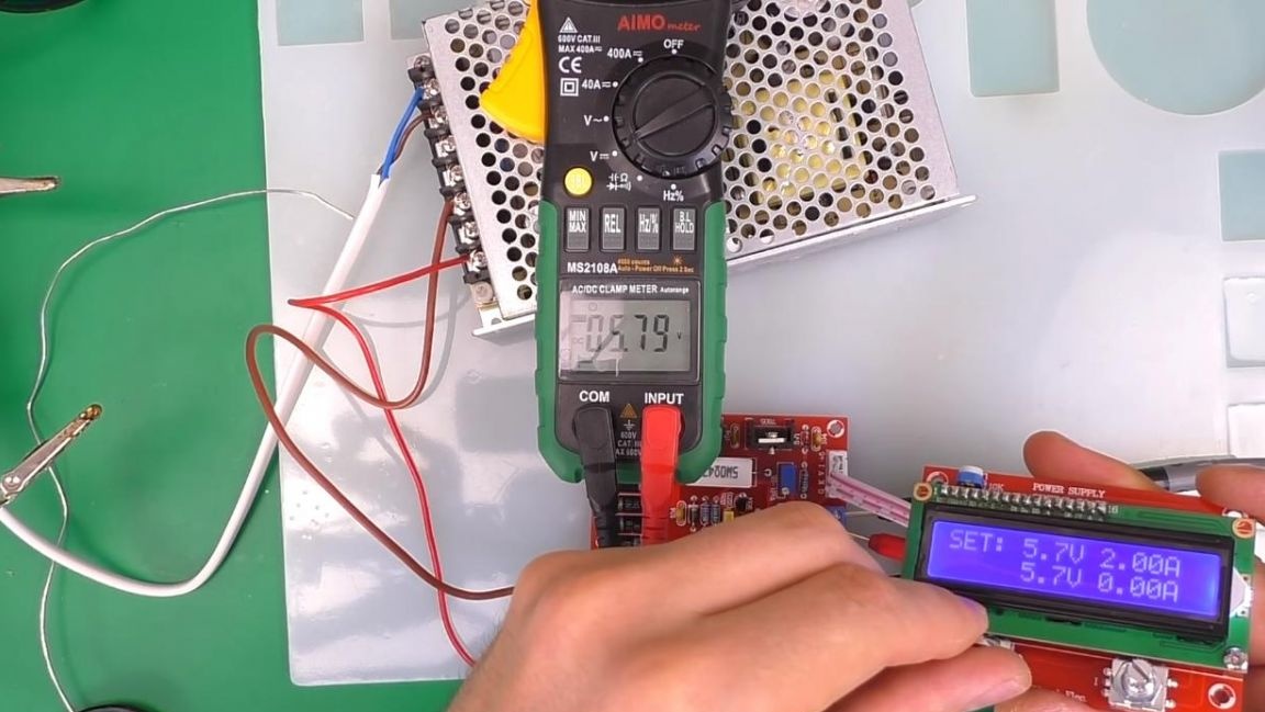
We connect a multimeter to the output and check the operation of the encoders, using them you can adjust both current and voltage. This kit kit is perfect for those who want to assemble their laboratory power supply and do not know where to start.
Also, this radio designer will be useful in order to gain experience in their assembly.
That's all for me, thank you all for your attention and creative success.