
Hello to all lovers homemade. In this article I will tell you how to make an oscilloscope with a case do it yourself, in the assembly of which the kit kit will help, you can order it by the link at the end of the article. Such a radio designer will be useful for gaining experience in working with radio electronics, as well as for use in various homemade products where this device is needed, for example, when measuring the power of an amplifier.
Before reading this article, I suggest watching a video with a detailed assembly process, as well as testing this kit.
In order to make an oscilloscope with a case yourself, you will need:
* Soldering iron, solder, flux
* Device for soldering "third hand"
* Crosshead screwdriver
* Silicone soldering mat
* Multimeter
* Side cutters
* 9V power supply
Step one.
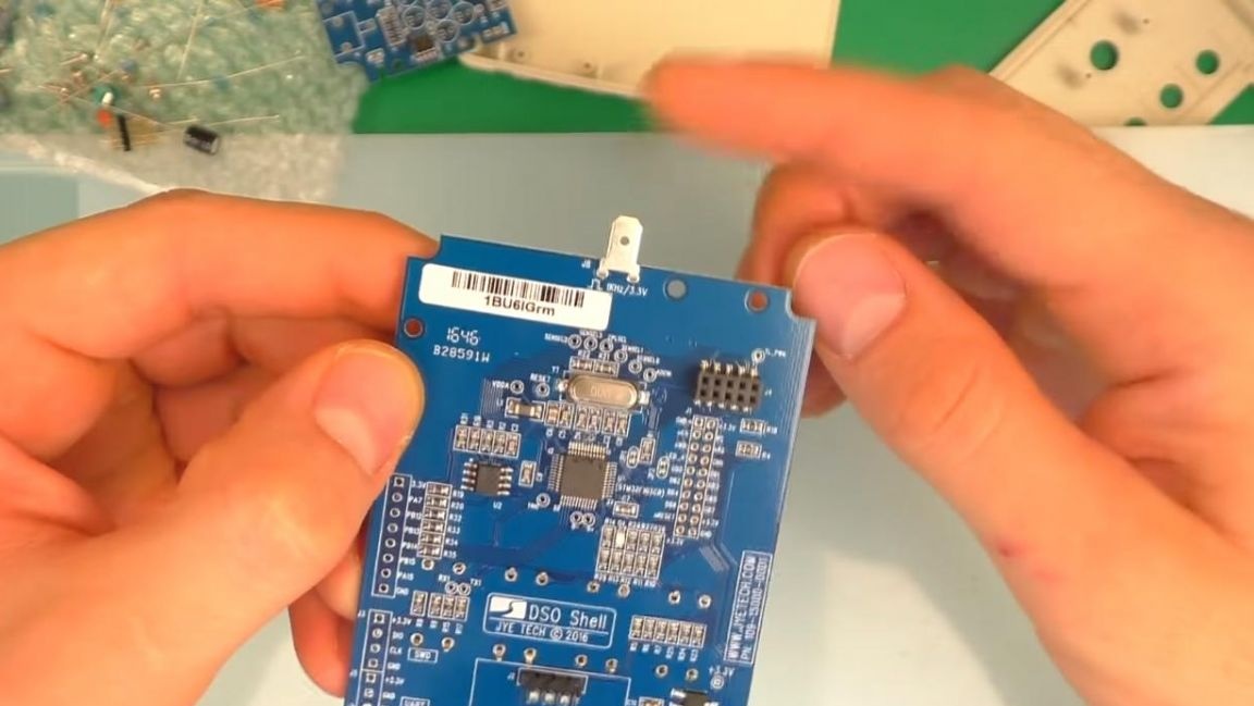
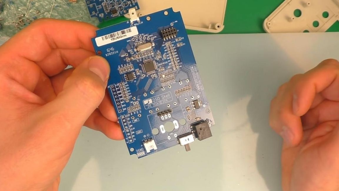
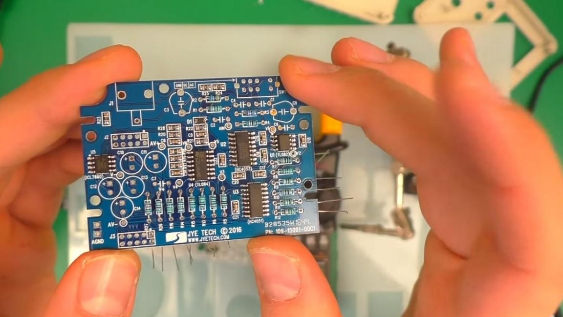
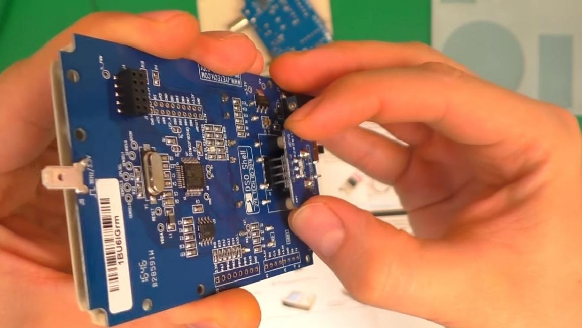
The kit kit kit has two printed circuit boards with metallized holes, their quality is at a fairly high level, there is also an assembly instruction, which is quite convenient.
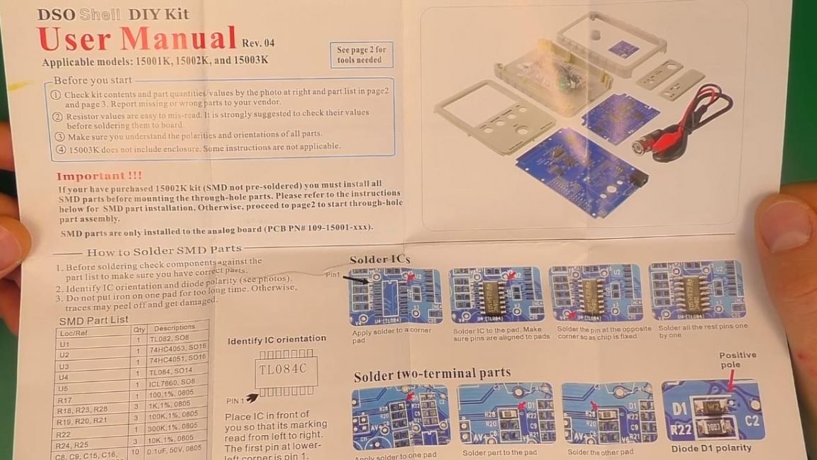
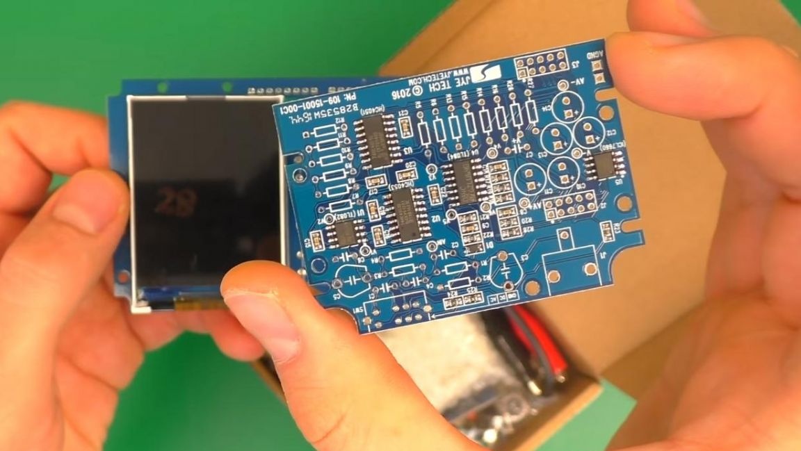
One of the boards already has SMD chips. The kit contains a case in which there will be boards in the future.
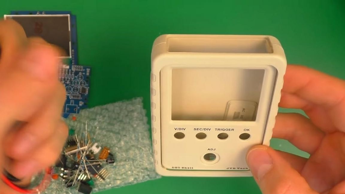
There are not so many radio components here, so a lot of time for assembly will not be needed.
Step Two
First, install the buttons on the board, and then the contact of the signal generator for tuning.

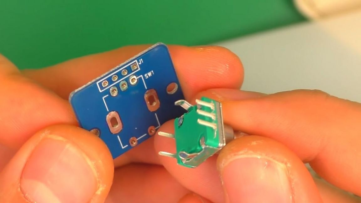
After that, insert the switch and connector into place.
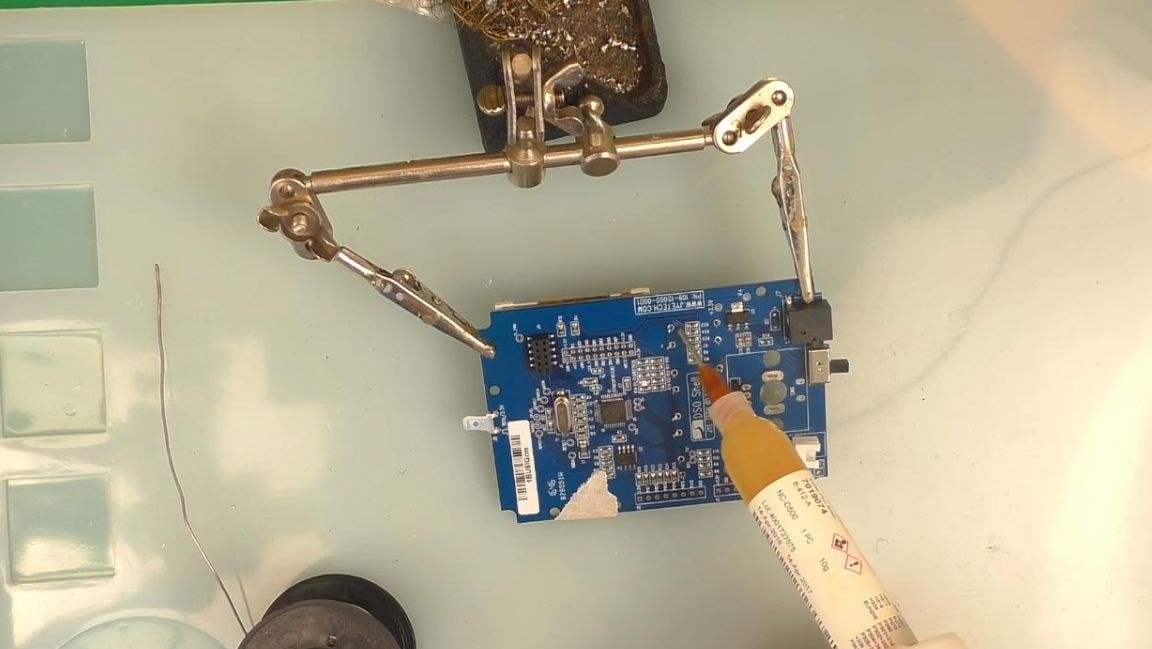
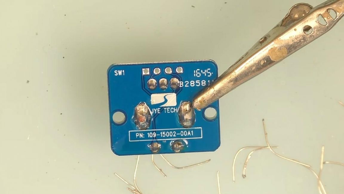
We fix the board in the “third hand” soldering device and apply the flux, after which we solder the parts with the soldering iron that we installed earlier, adding solder.
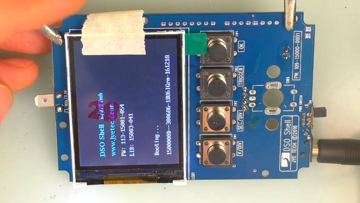
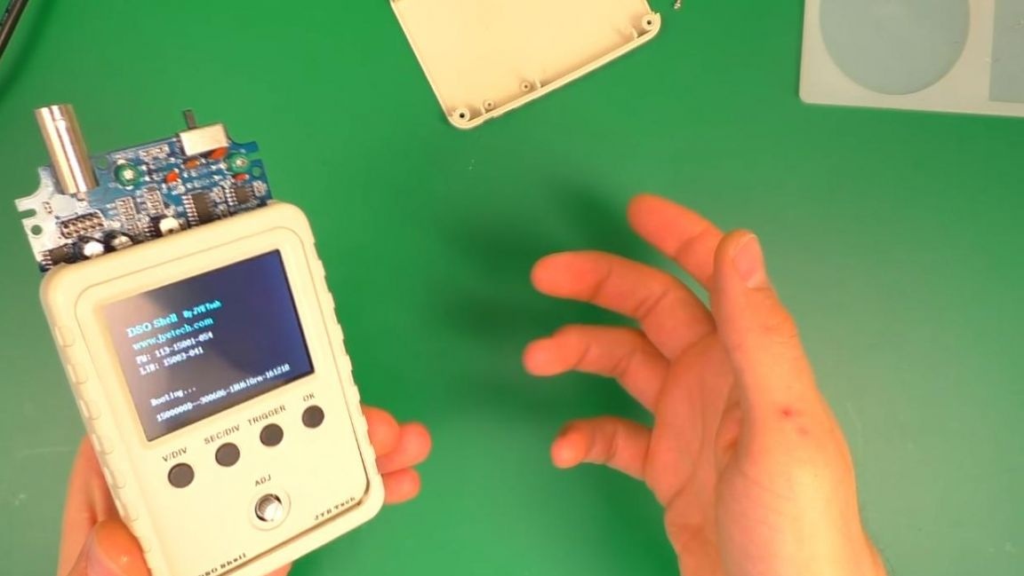
Then we check the board, connect the power supply to the socket that was soldered from the factory and if the display and buttons work, then go to the next step.
Step Three
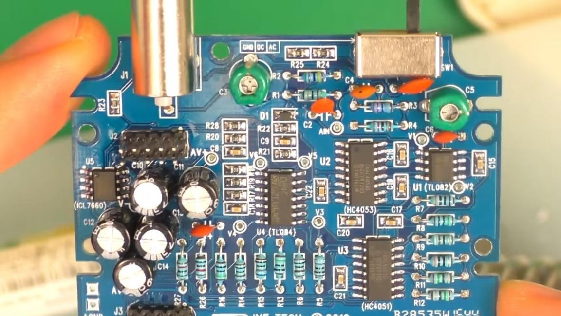
Now install the resistors on the other board. Before you insert the resistors on the board, you need to measure their resistance, you can do this with a multimeter, color coding and a lookup table, as well as an online calculator.
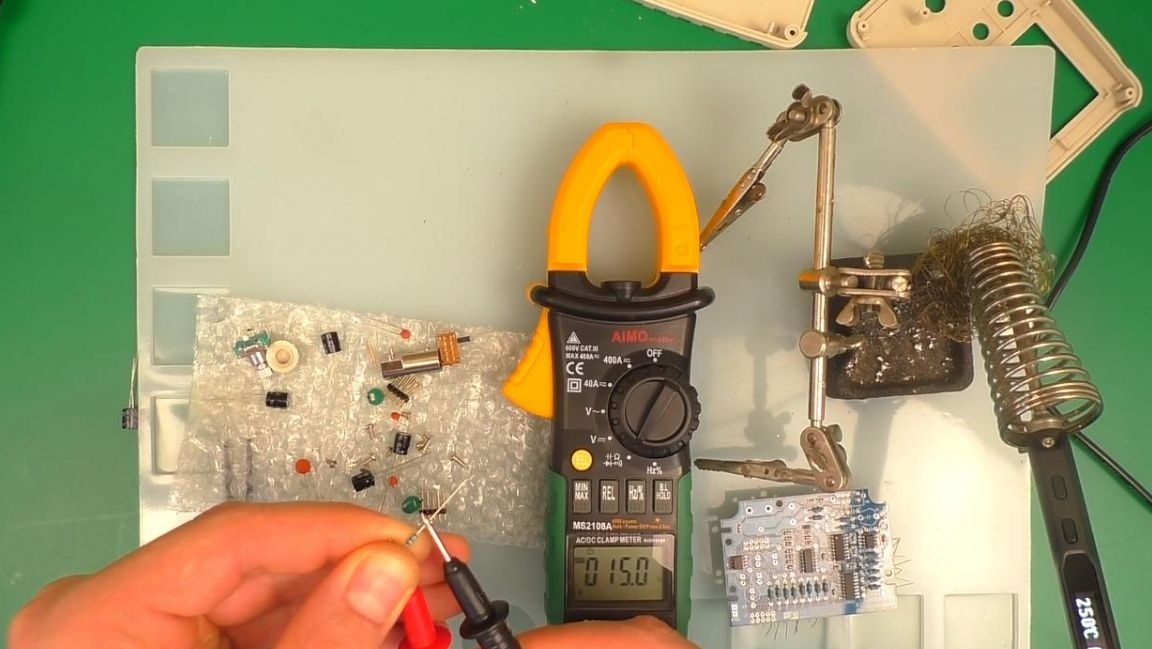
Determining the values with a multimeter is the easiest and faster, we install the resistors in place according to the instructions.
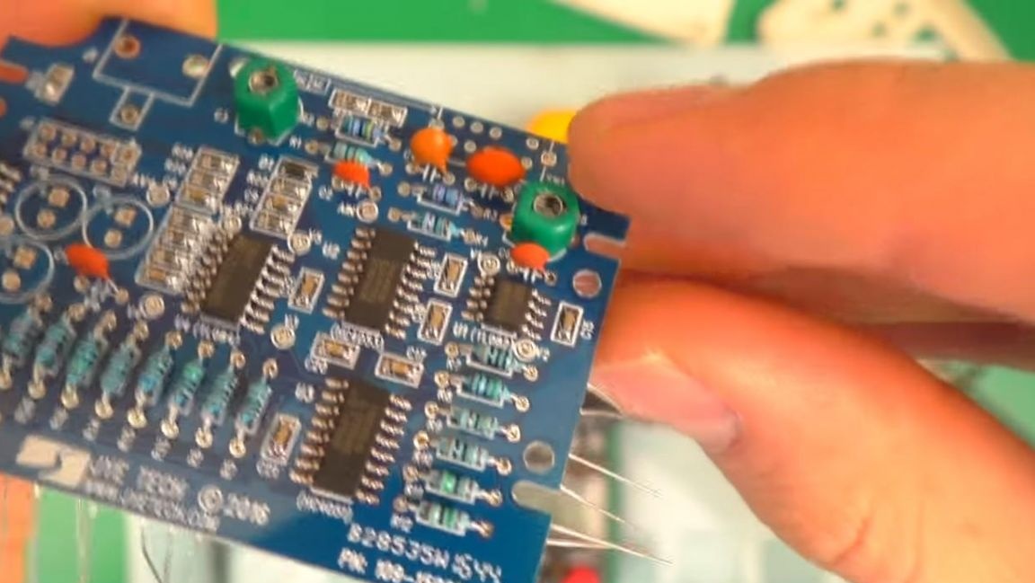
Next, insert non-polar ceramic capacitors onto the board.

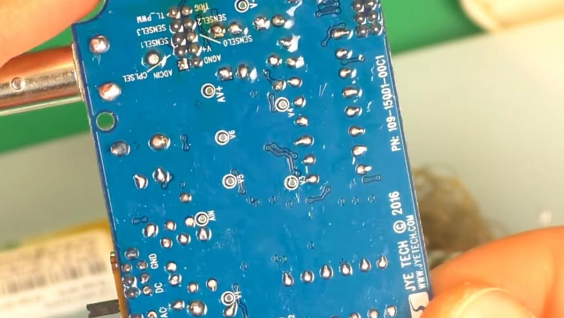
On the reverse side of the board, we bend the conclusions so that they do not fall out when soldering. After that we install tuning capacitors.
On the reverse side, we also overtake the conclusions.
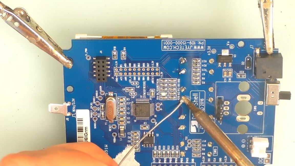
Next, we fix the board in the "third hand" soldering device and solder the conclusions to the contacts using a soldering iron.
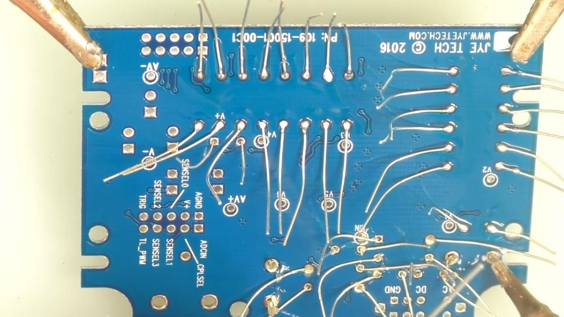
The excess parts of the terminals are removed with side cutters. When biting the conclusions with side cutters, be careful, as the tracks can be torn from the board.

Step Four
We set the conclusions for connecting the second board, the switch and the polar electrolytic capacitors, observing the polarity and ratings, plus this is the long leg, minus-short, the polarity is marked on the board, then solder everything with a soldering iron. Extra conclusions are also removed with side cutters.
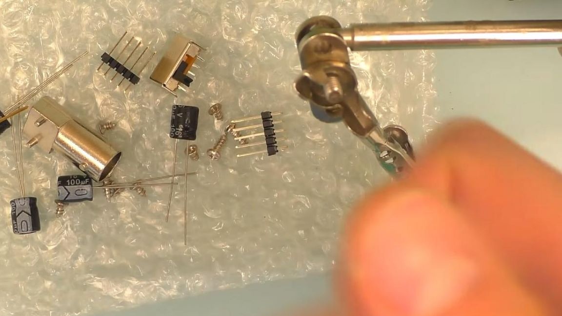
Next, install the encoder on a small separate board, it will not work to confuse the situation, on the one hand there are two contacts, on the other-three and soldered with a soldering iron.
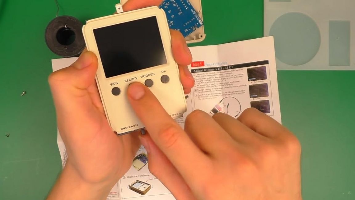
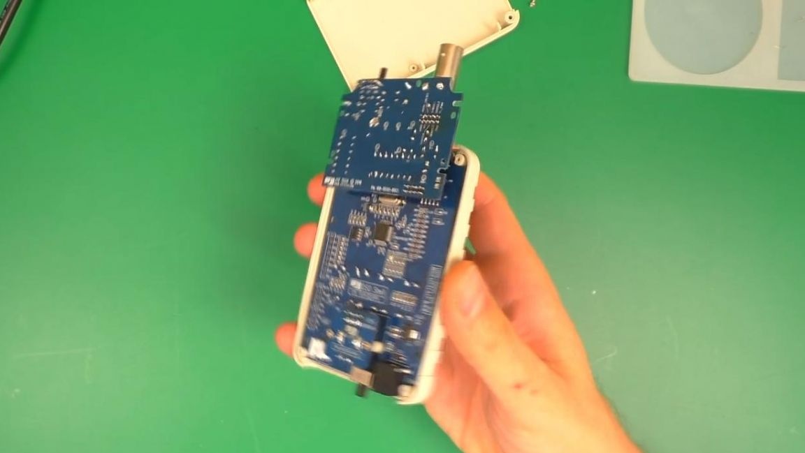
Then we put the display in the case, peel off the double-sided tape and glue the board to it, check if the buttons are pressed.

We connect a board with an encoder to the contacts and connect a second board to another connector.
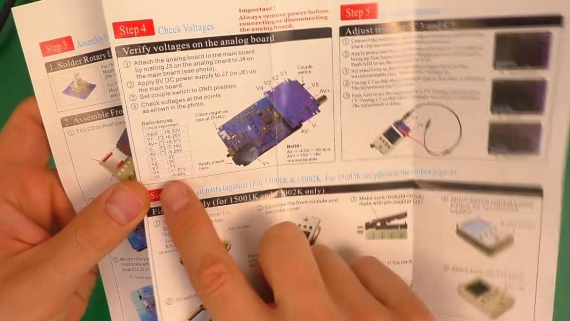
Step Five
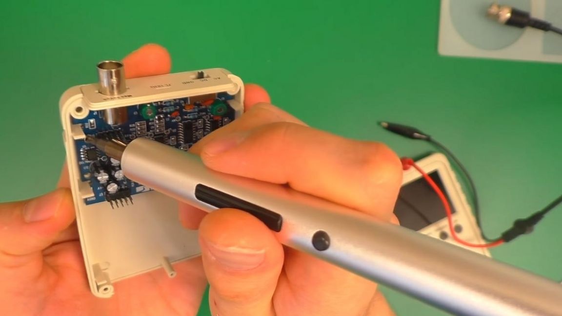
We connect the power supply with a voltage of 9V and check the voltage at various points according to the instructions using a multimeter, if everything is correct, go on.
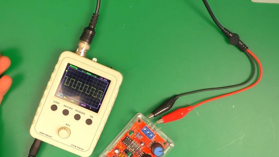
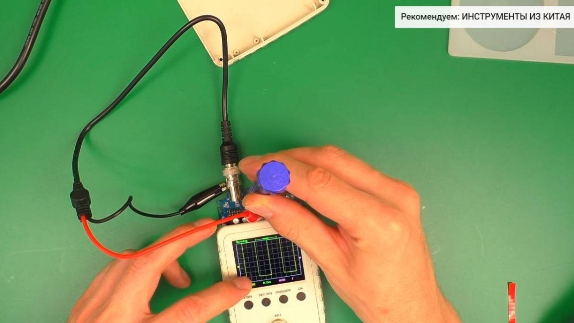
We insert the probes and connect the negative to the mass, and the positive to the output of the signal generator and rotate the variable resistor until the square signal becomes the most even.
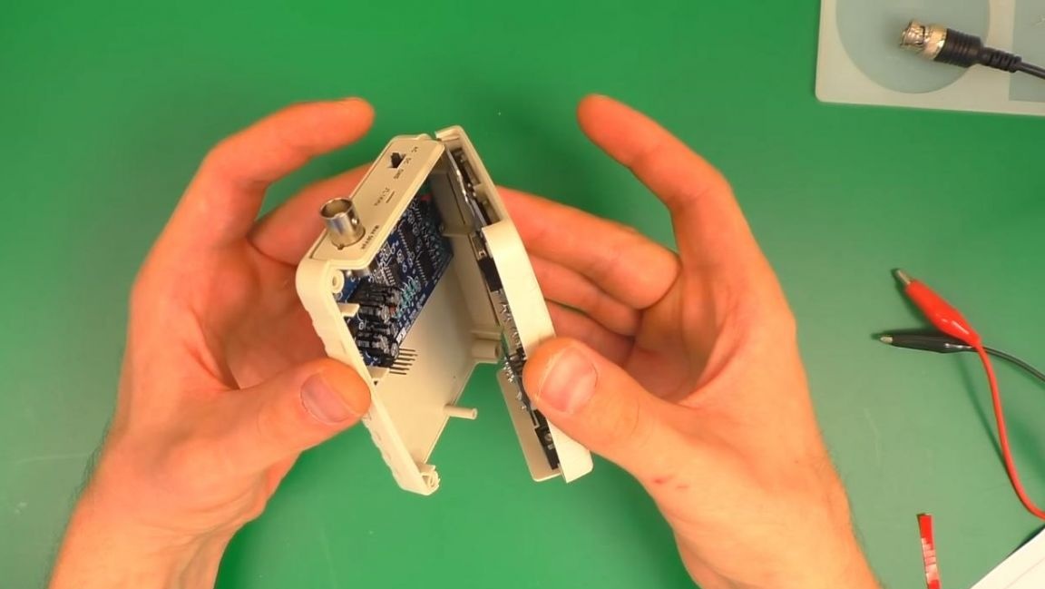
Next, we disconnect the boards, turn off the probe and install the board in the back of the case and fasten four screws with a Phillips screwdriver.
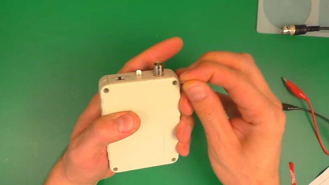
Then we connect the two halves of the case with the boards together and fasten with screws.
Step Six
We check the oscilloscope, connect the power and connect the signal generator to the probes, depending on the installed signal, the graph is displayed, its scale can be reduced or increased. This kit kit can be advised to beginners and those who just want to try to assemble a radio designer with their own hands.
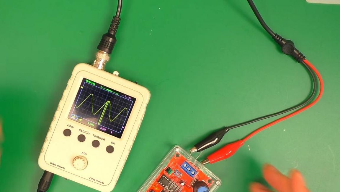
Also, using an oscilloscope, you can measure the parameters of an electrical signal, for example, you can measure the maximum power of the amplifier before distortion, which can be tracked on the display.
That's all for me, thank you all for your attention and creative success.