
Hello to all lovers homemade. In this article I will tell you how to make a watch with LED projection do it yourself, in the assembly of which the kit kit will help, a link to it will be at the end of the article. This radio designer will be useful for assembling radio amateurs, as well as for those who want to first test their strength in working with a soldering iron. Such a watch will look great anywhere, and a rotating projection on the LEDs will only add originality.
Before reading this article, I suggest watching a video showing the entire assembly process of this kit kit, as well as full testing.
In order to make a watch with LED projection, you will need:
* Kit
* Soldering iron, flux, solder
* Device for soldering "third hand"
* Tweezers
* USB whistle, you can buy
* Thermogun
* Side cutters
* Silicone soldering mat
* Power supply with USB port
Step one.
To begin, consider what is included in the kit kit. There are several bags with boards, there are three different sizes in all, they are marked for ease of assembly, there are also SMD resistors and LEDs, which are quite numerous.
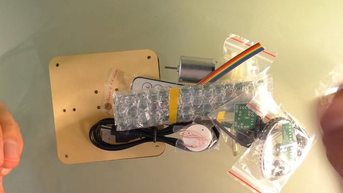
A large printed circuit board will be driven by an electric motor, to which there is a special plexiglass case for greater stability.
In a separate bag, place all the details for the motor power supply, unlike the other two boards, it will be assembled on DIP radio components, that is, the board has holes for installation.
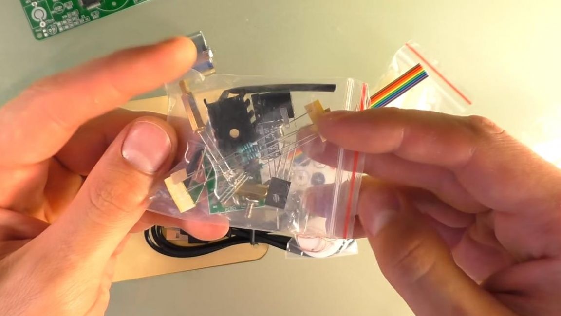
A special cable is provided for connecting the power, and you can control the clock using the remote control. Assembly instructions are not included in the kit, but there is a link on the seller’s page where you can download it in e versions where everything is disassembled in sufficient detail to the smallest detail, including the firmware process. Having dealt with the kit, we proceed to the assembly itself.
Step Two
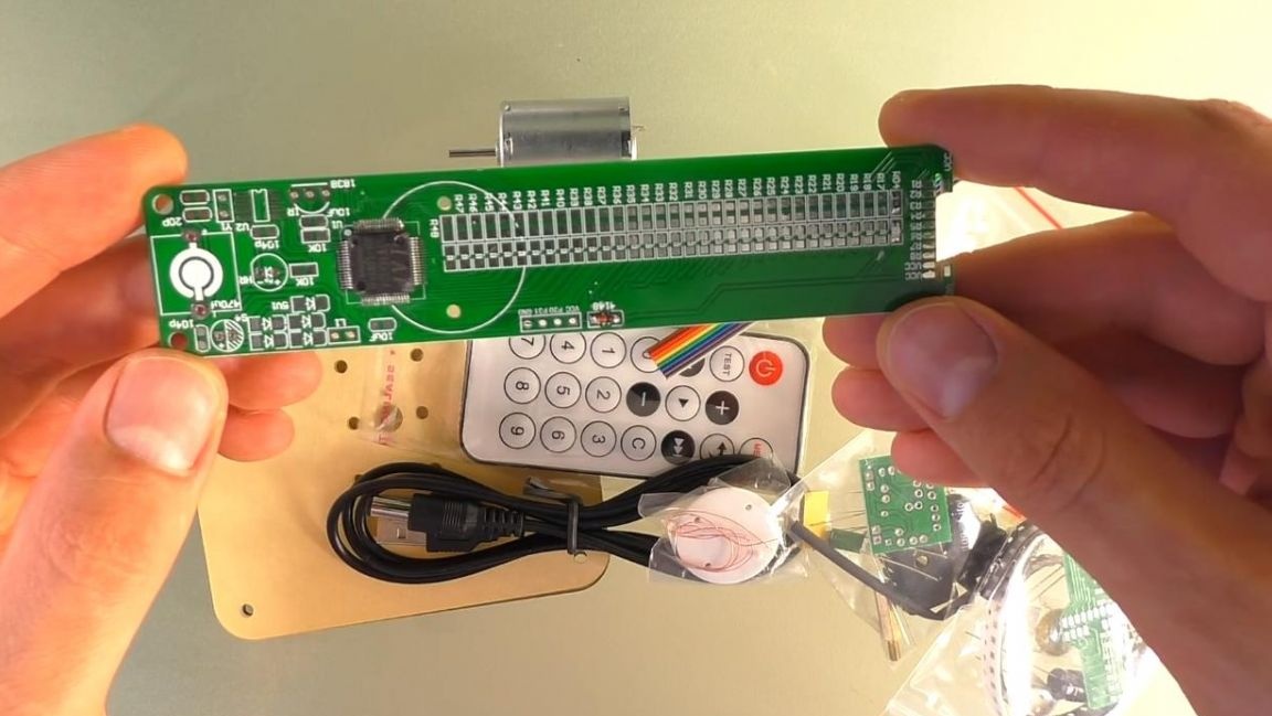
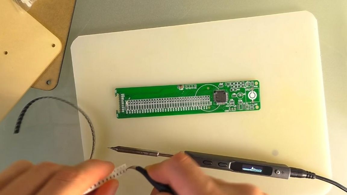
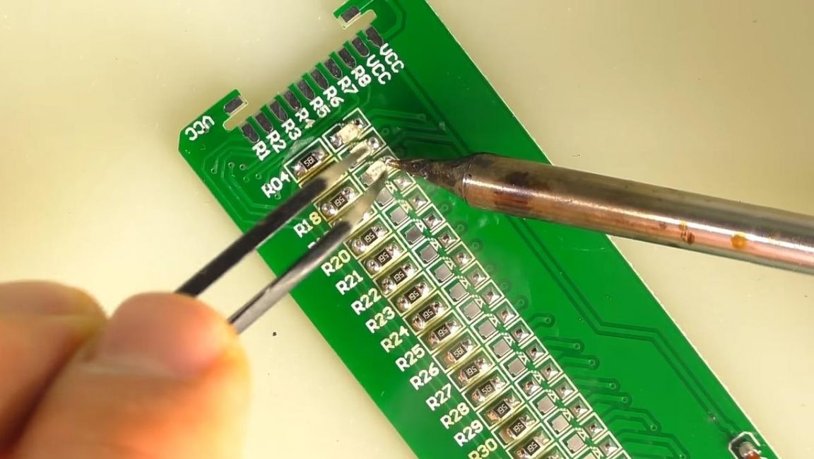
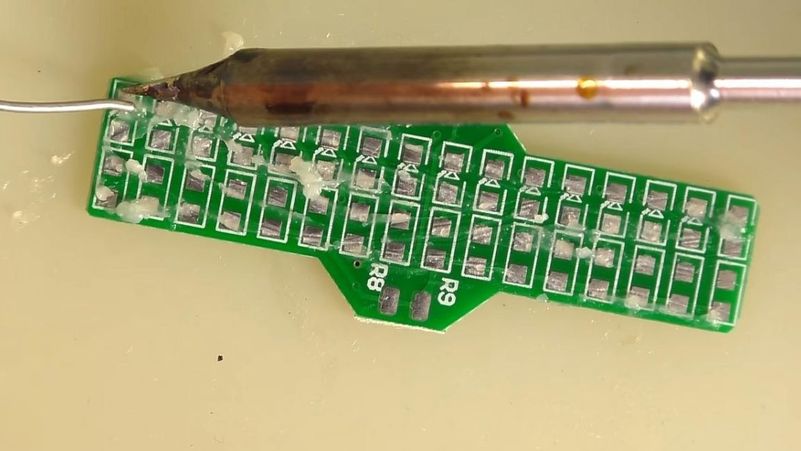
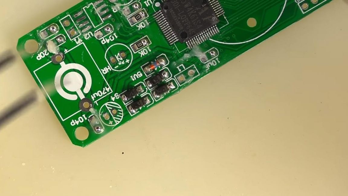
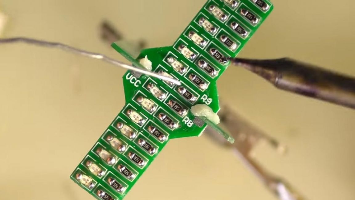
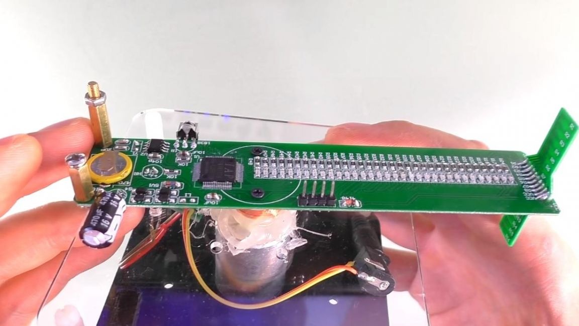
First of all, install the component SMD board on the largest part of the kit, the microcircuit is already pre-soldered on it, since to install it you would need a soldering hair dryer. It is not necessary to determine the resistance of SMD resistors, since here they have the same ratings, which is very convenient. Using tweezers, open the tape of the resistors and pour them onto the silicone soldering mat.
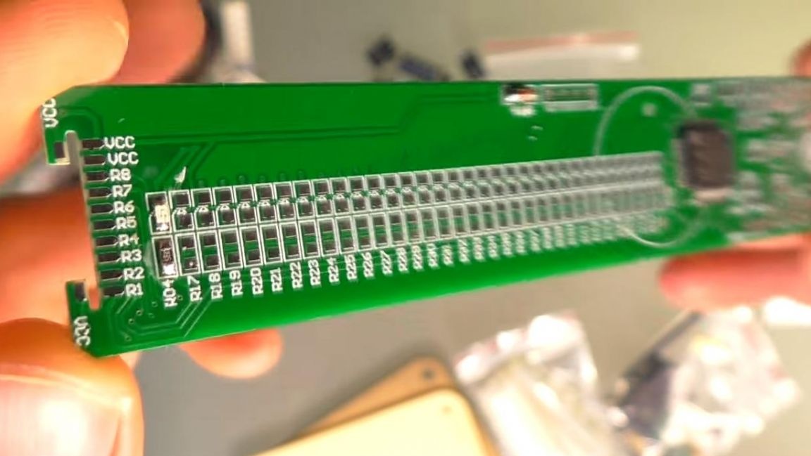
To install so many parts will require a lot of patience. One resistor and LED are already soldered from the factory, this is done in order to understand their proper location.
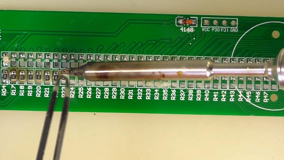
We apply flux to the board contacts and tin them with a soldering iron.
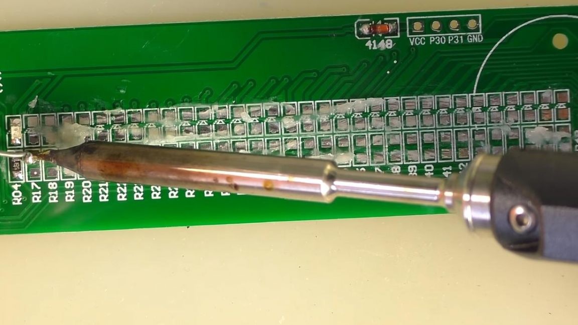
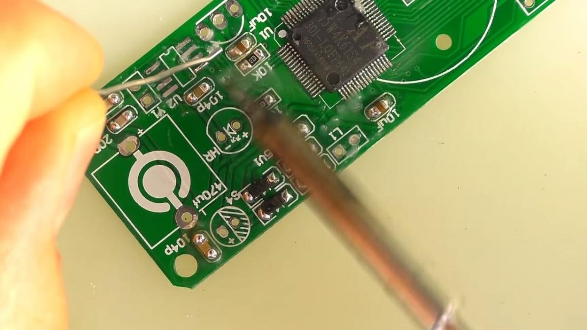
Then with the help of tweezers we put the resistor in its place and solder it with a soldering iron.
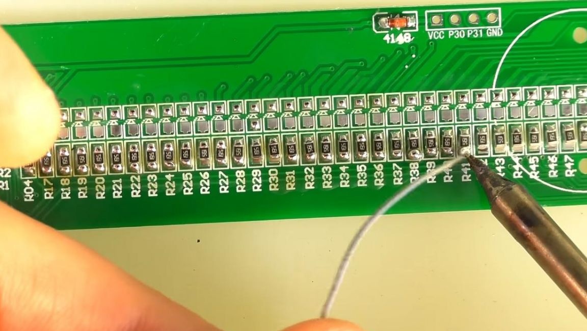
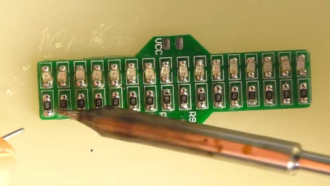
Next, soldering all the resistors on one contact, solder their second side and add solder if necessary.
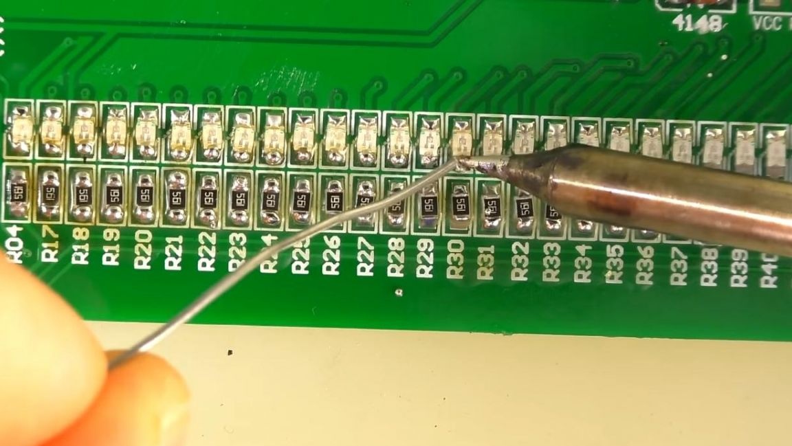
When all the resistors are soldered, go to the LEDs, their green dot should be in the same direction as the strip on the board marking, otherwise the LEDs will not work and you need to change their position. We solder the LEDs in the same way as resistors, first on the one hand, and then on the other.
Step Three
We proceed to the assembly of a small board, apply a flux to it and, similarly to the previous board, solder the LEDs and resistors.
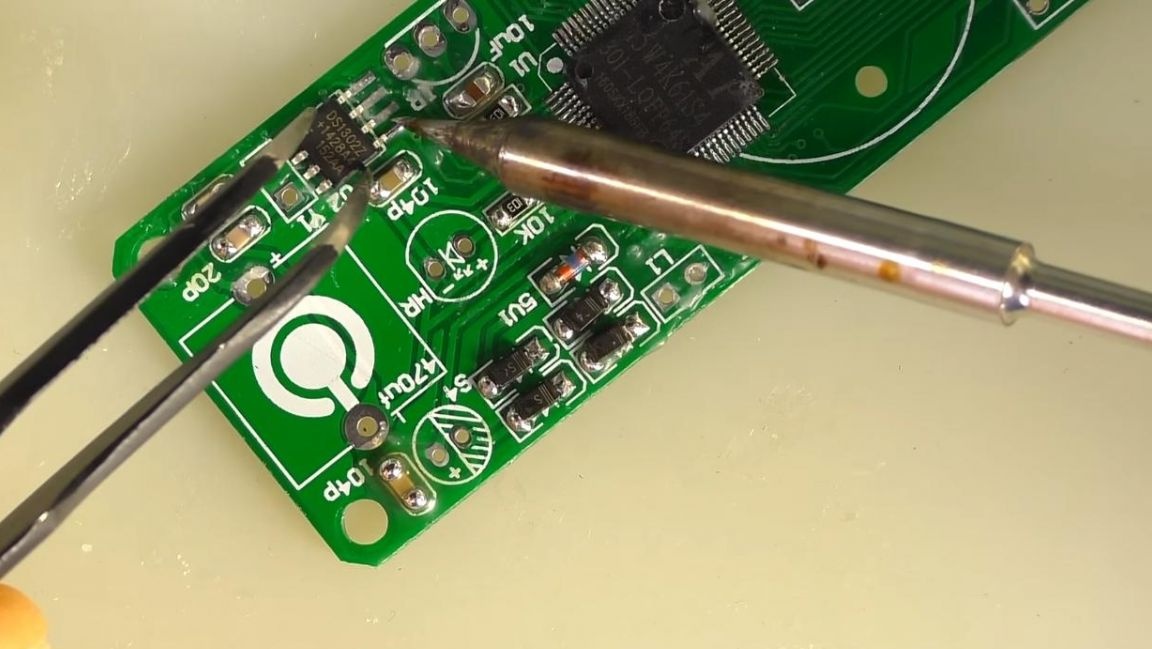
Next, on a large board, we place SMD diodes, we orient ourselves by the strip on the case and the board marking.
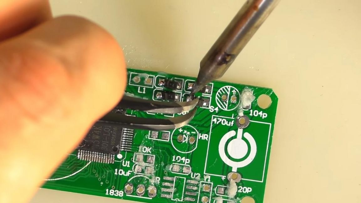
Then we solder the remaining resistors according to the instructions, as well as ceramic capacitors, the values of which are signed on the tape.
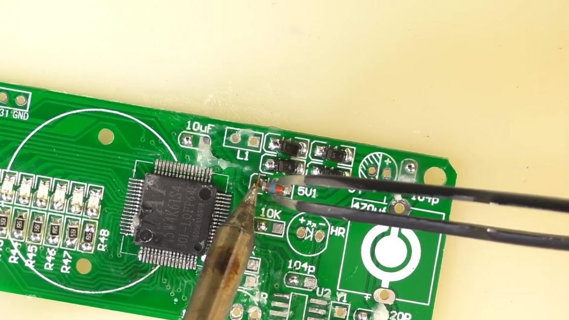
We install the microcircuit on the board, being guided by the key on the board and on the case in the form of a dot. We solder its conclusions separately so as not to overheat the microcircuit. If the conclusions are soldered to each other, then the excess solder can be removed with a copper braid.
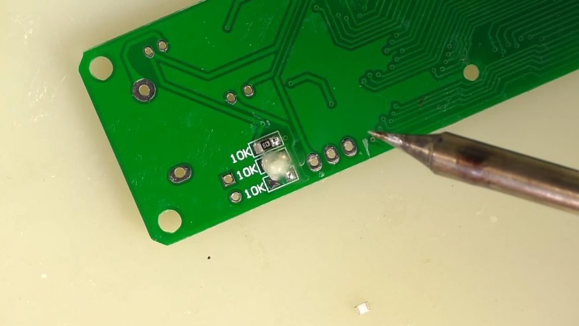
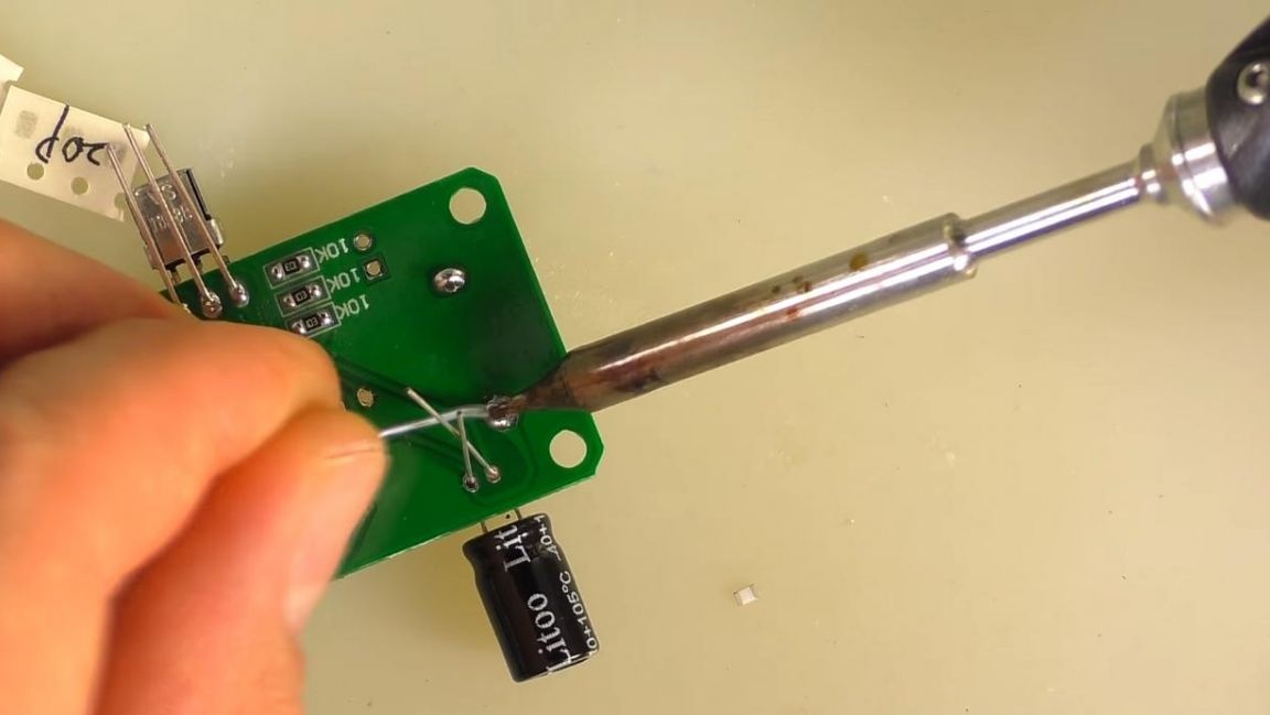
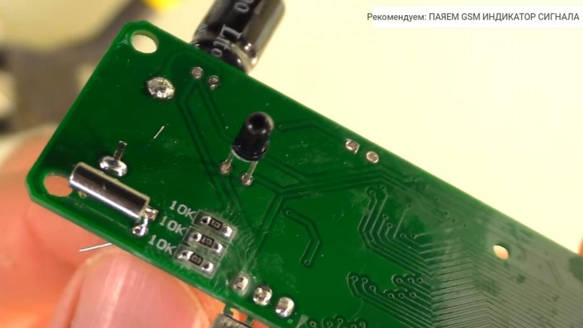
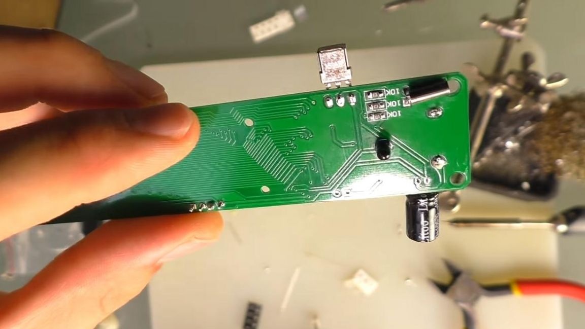
On the other hand, we solder three 10 kΩ resistors.
Step Four
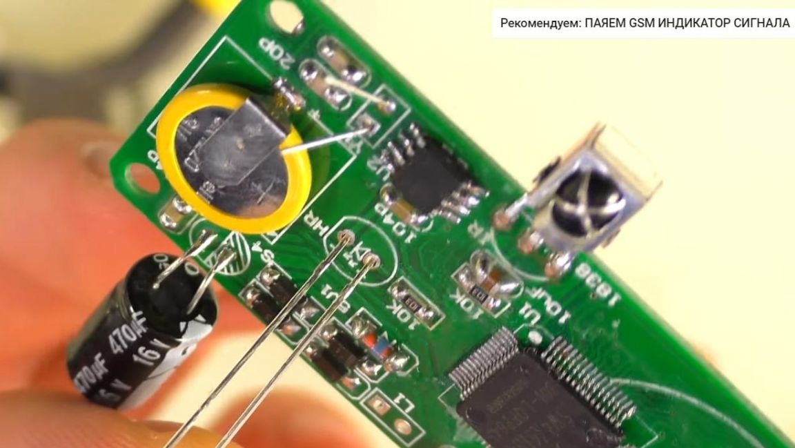
Now we install the receiver, the battery on the board. We also insert a 470 microfarad capacitor, observing the polarity, plus this is a long leg, minus is short, on the board the minus contact is indicated by hatching.
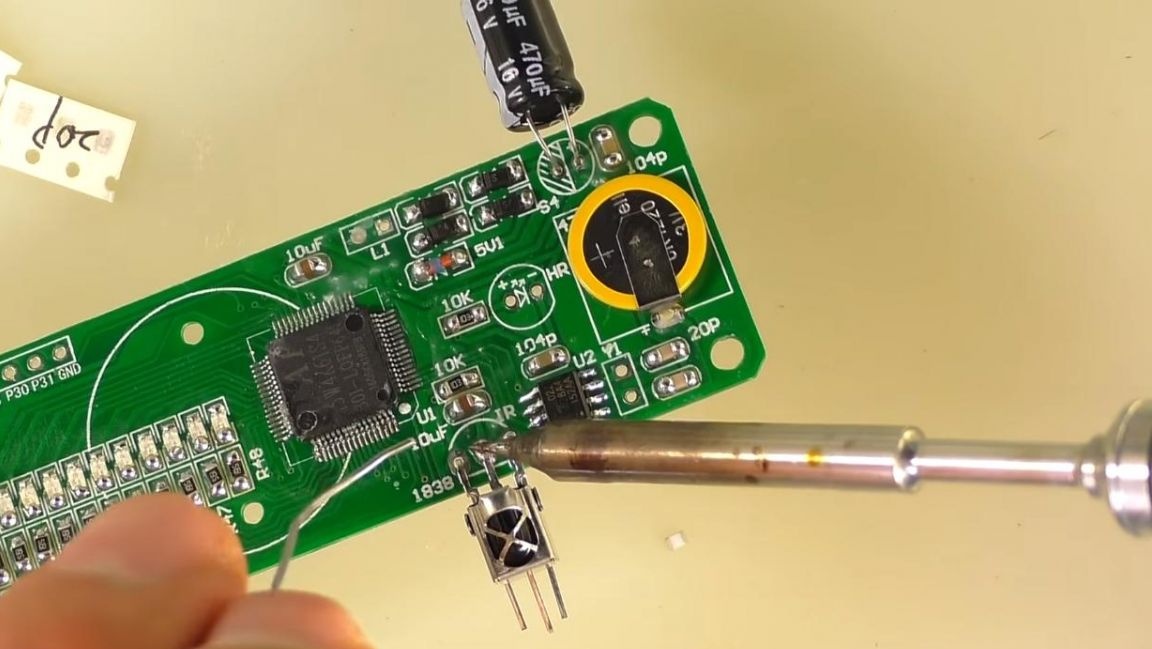
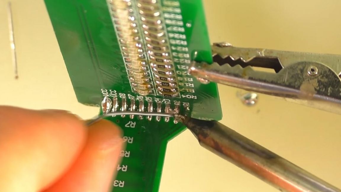
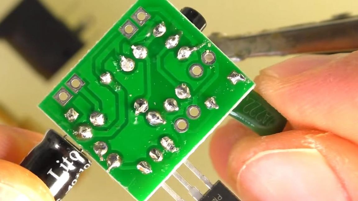
We solder the conclusions of the radio components on the back side of the board and remove their residues with the help of side cutters. When removing pins with side cutters, be careful as you can tear the track off the board.
On the same side, solder quartz and a diode, where the long leg is plus, short-minus, minus on the board is indicated by a dash.
We solder a small and a large board to each other by inserting it into a special groove. On the other hand, solder their contacts with each other.
Next, we wash off the flux from the board, this can be done with a brush and alcohol or galosh gasoline.
Step Five
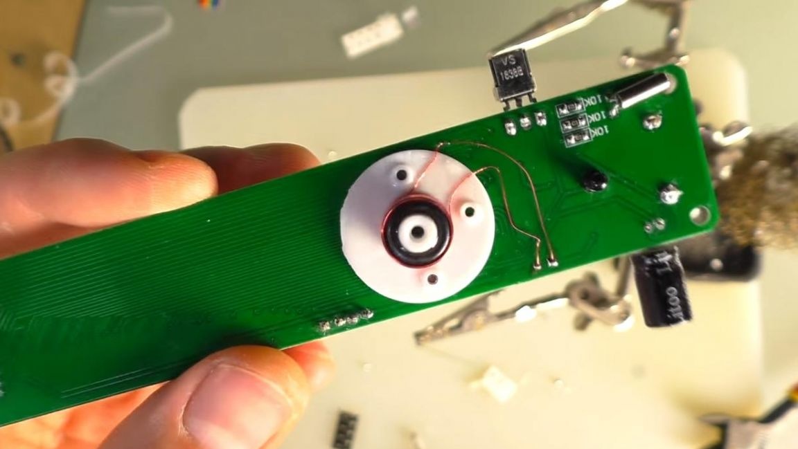
We insert screws into the special holes on the large board and screw the coil on them, and solder the leads from it to two contacts. In order for the coil mount to hold securely, you need to bite off a small pin on the back side with side cutters, this is an extra part from casting.
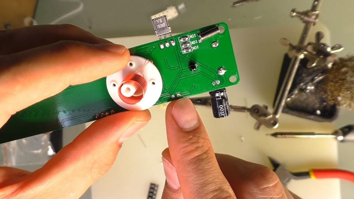
Glue the core and coil onto superglue and give a little time for complete drying.
After assembling the main board, you can set it aside for a while and assemble the last board.
Step Six
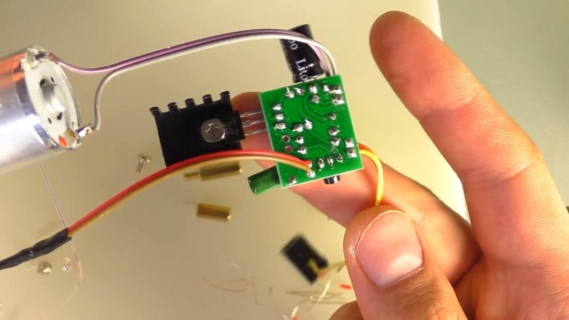
We assemble the power supply. We install radio components on a small board, according to the instructions.
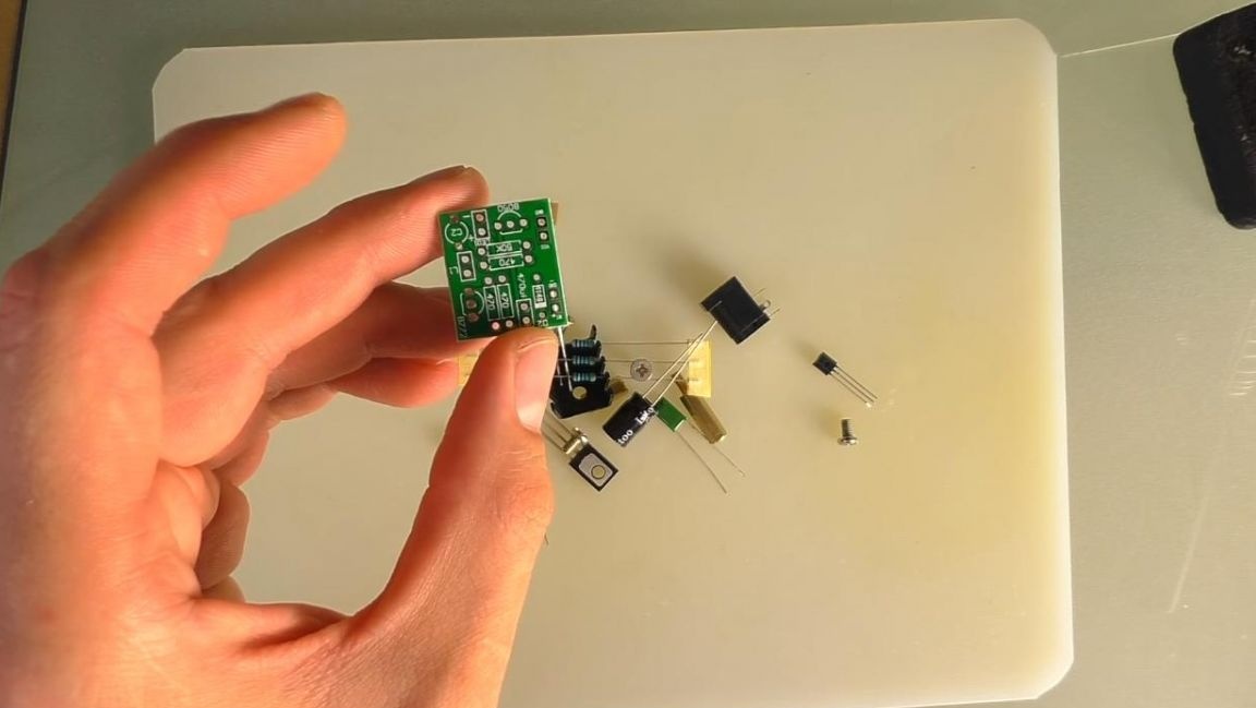
We install resistors without determining their value, since there is only one resistor of another resistance. We put a jumper in place of D2. We also install an electrolytic capacitor, observing the polarity. We put a ceramic capacitor, transistors, guided by the pattern of the board, repeating its shape.
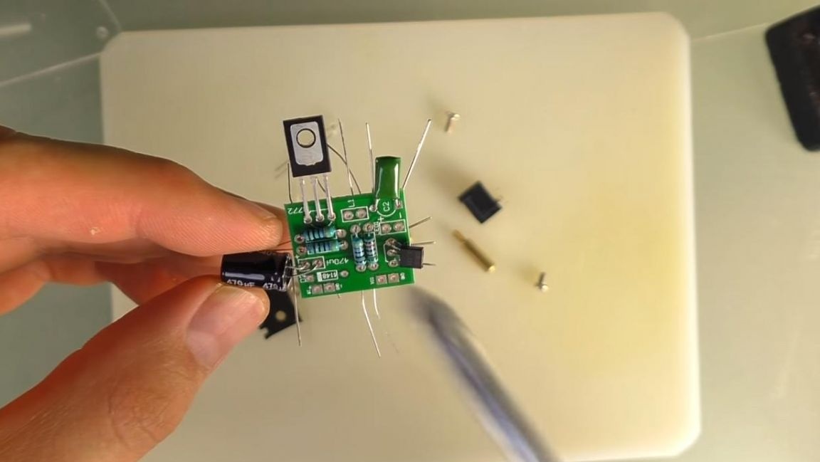
We do not solder the LED at this stage, since it will be mounted on the case and connected to the board through wires. On the back side of the board, we bend the conclusions of the parts so that they do not fall out when soldering and fixing the board in the “third hand” device, solder the legs to the contacts. Then we remove the remnants of the findings with side cutters.
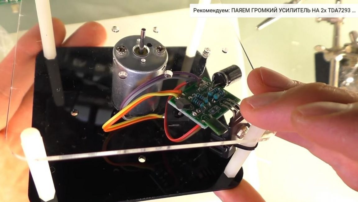
In the kit there was a loop of multi-colored wires, disconnect them and solder to the board. We connect an LED to two of them, plus which is a long terminal; on the board it is shown in the form of a triangle. We install it on a plexiglass panel in a special hole.
We solder the electric motor to the other wires and fasten it to the same plexiglass panel with two screws. To connect power, a socket is provided, which must be connected through wires to the board.
Seventh step.
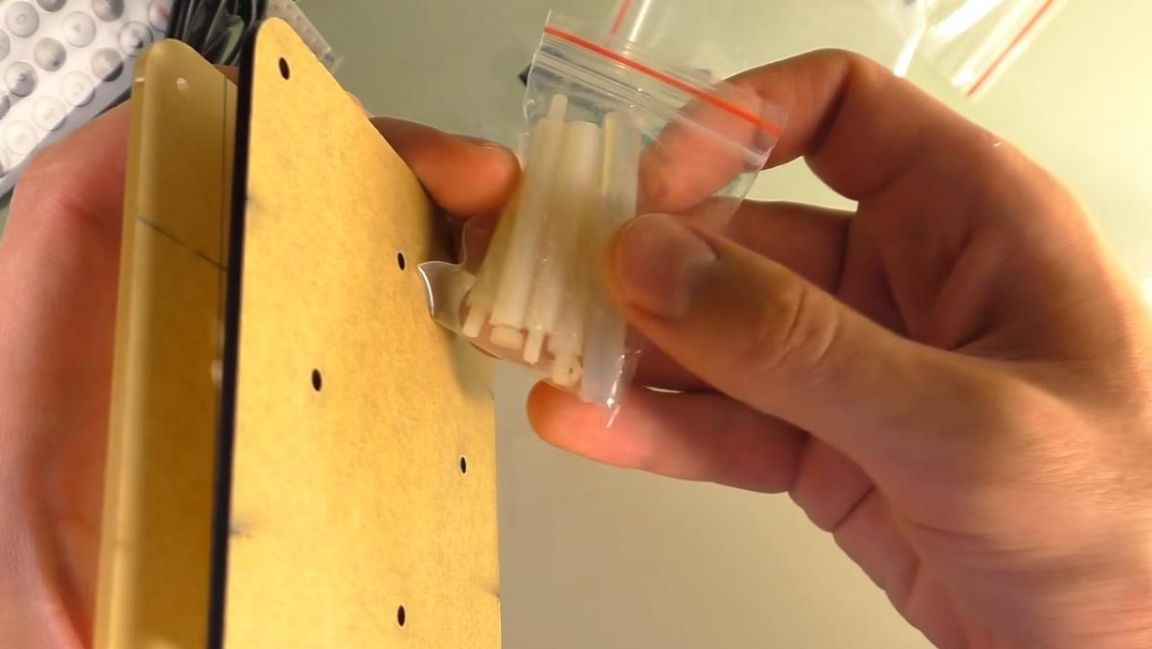
We assemble the body from plexiglass.We connect the upper part of the case with the bottom using special plastic racks, tighten them from the bottom with nuts. We fix the cable tie onto one of the racks.
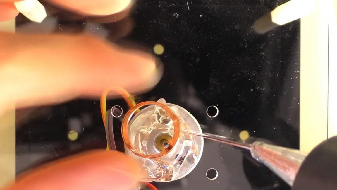
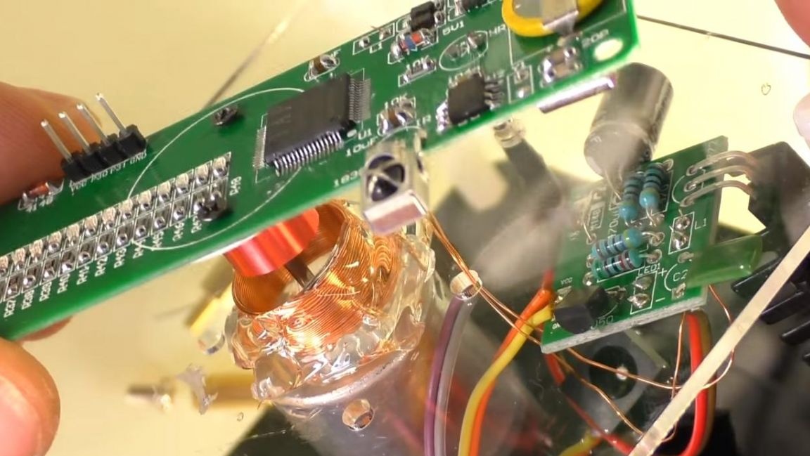
Glue the coil to the upper part using a heat gun, it must be positioned strictly in the middle relative to the motor shaft, solder the leads from the coil to the power board by threading through the hole. When installing the coil, leave a small distance between the mounting screws of the motor so that the circuit does not short-circuit.
We install the main board on the electric motor shaft, current will be transmitted through the circuits of the coils, which will power the entire board and LEDs.
We supply power to the device and balance the large board with two threaded spacers installed on one edge.
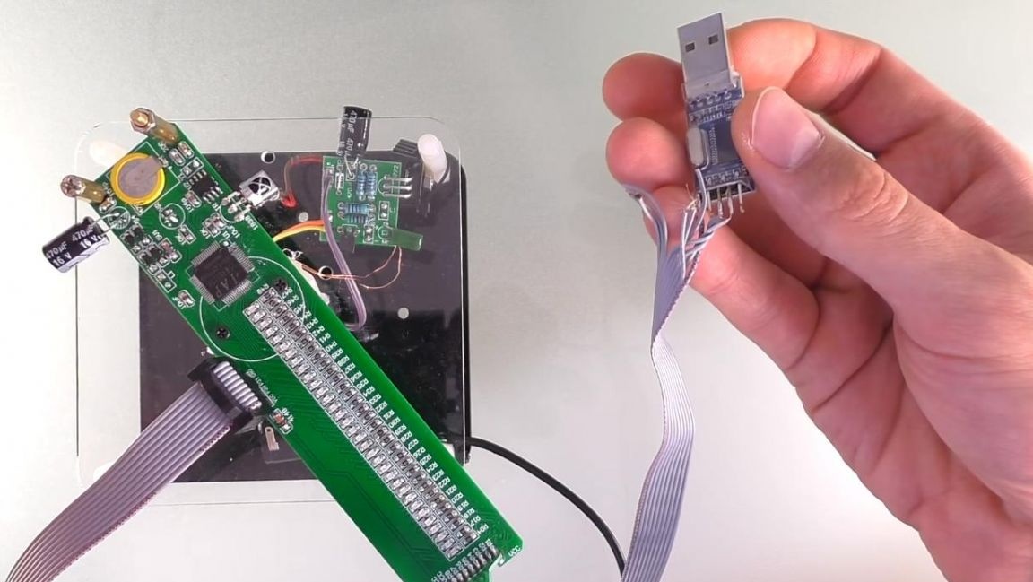
Next, install the firmware using a USB whistle, you can download the firmware file from the link on the seller’s page.
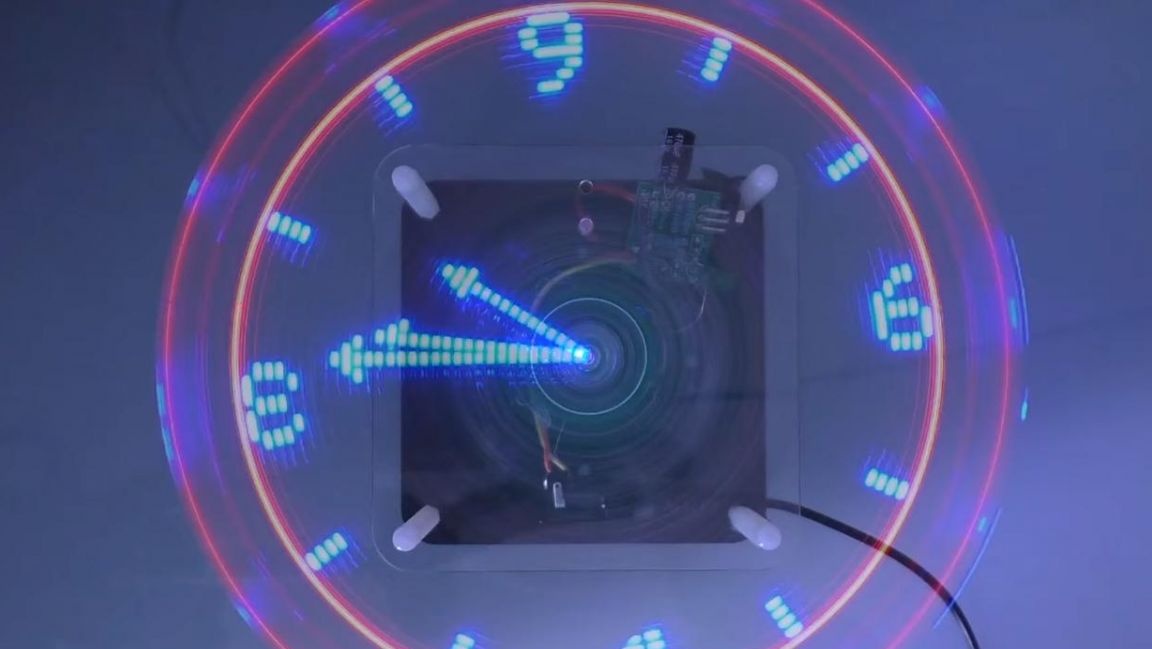
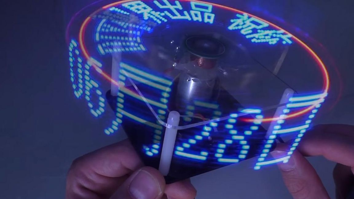
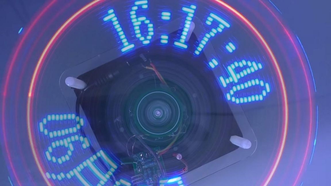
After the firmware, the clock with the LED projection is completely ready, it has several time display modes, both analogue and digital, with date information output.
That's all for me, thank you all for your attention and creative success.