
Hello to all lovers homemade. In this article I will tell you how to make a low frequency amplifier do it yourself, whose power is 60 watts, a kit kit will help in its assembly, you can order it by the link at the end of the article. This radio designer will be a great start for beginner hams, as it has a modest amount of parts, which will not make a mistake in the assembly process. Such a low-frequency amplifier can be used in various home-made products, for example, a home subwoofer or other speaker system that requires an amplifier; in the future, if desired, it can be installed in a separate case.
Before you read the article, I suggest watching a video, which shows in detail the assembly process of the kit, as well as testing in work.
In order to make a 60-watt low-frequency amplifier with your own hands, you will need:
* Kit
* Soldering iron, flux, solder
* Device for soldering "third hand"
* Power supply bipolar with a voltage of 24 volts
* Side cutters
* Multimeter
Step one.
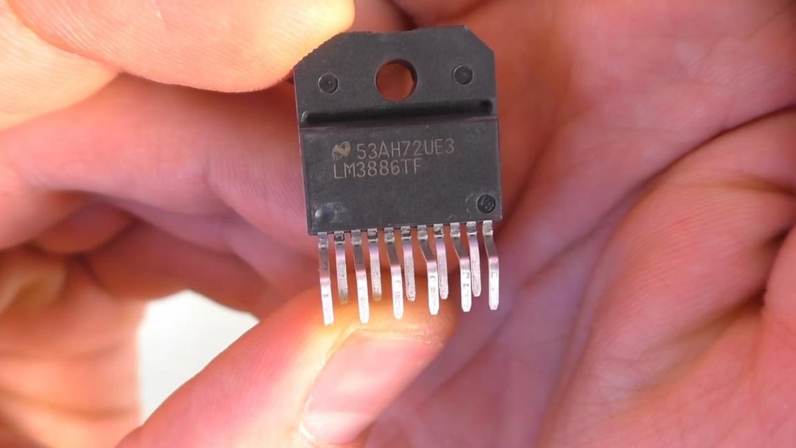
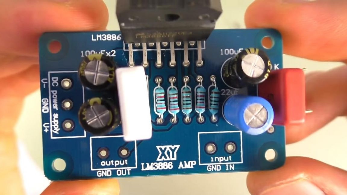
To begin, consider what is included in the kit kit. In a small bag fit all the parts, an amplifier chip, namely LM 3886TF, resistors, capacitors, as well as a screw for installing a radiator.
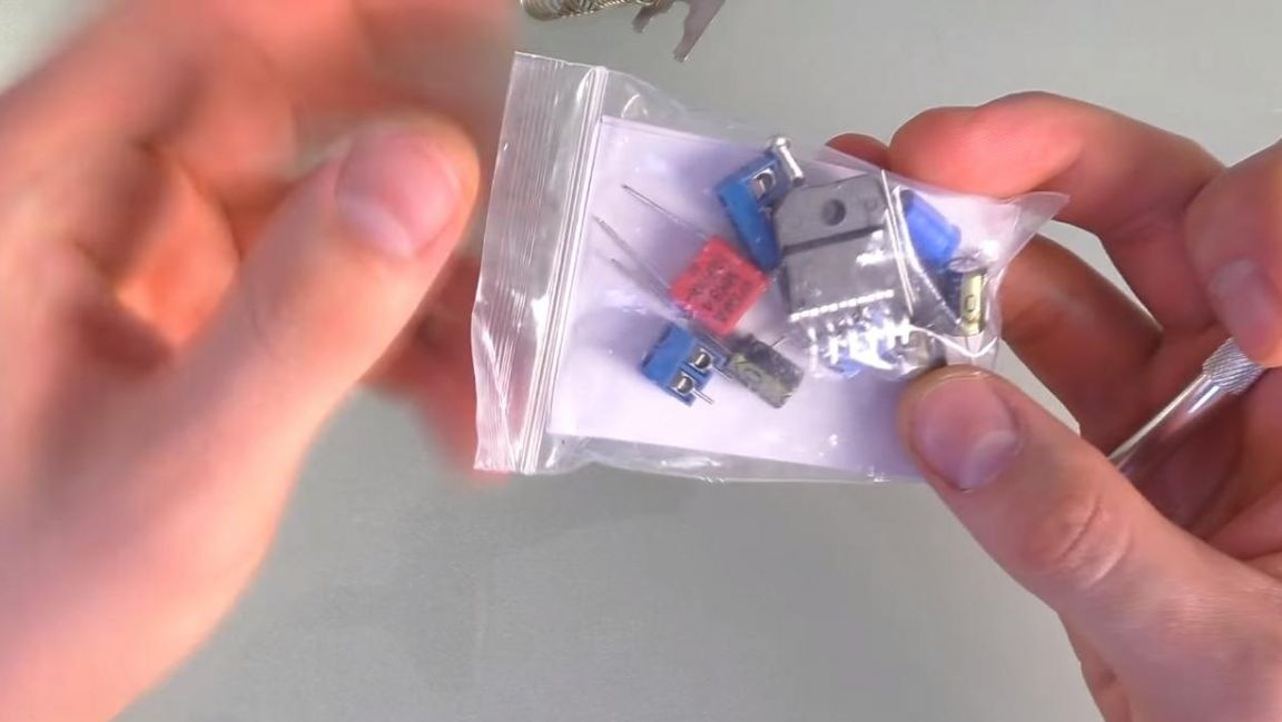
The case of the microcircuit is insulated, so installing it on a radiator does not require a special dielectric gasket.
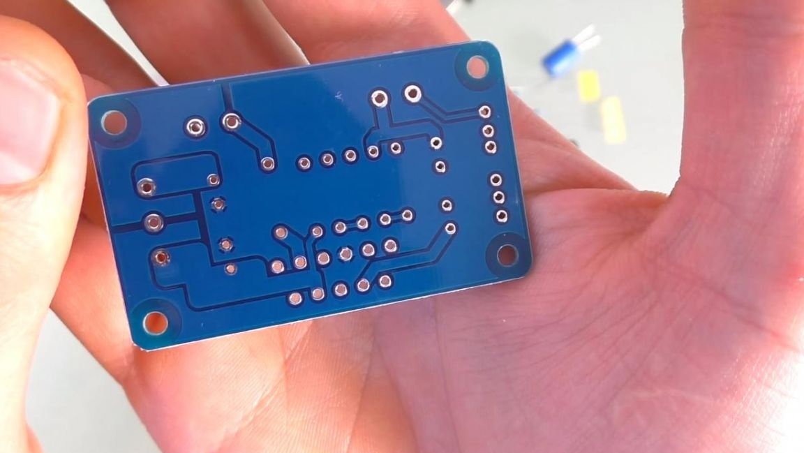
For ease of assembly, we also did not forget about the instructions, however, the board itself is marked with the ratings of all radio components. The printed circuit board is made with sufficient quality and has metallized holes on both sides. To make it convenient to fix the amplifier board in the housing, four holes for screws are provided on it.

Having dealt with the kit, we proceed to the assembly.
Step Two
First of all, we fix the board in the "third hand" soldering device and install the radio components. First, we insert a powerful 5-watt resistor, and then the remaining low-power resistors in their places, observing the ratings, you can determine their resistance using a multimeter, color coding, and also an online calculator. On the reverse side of the board, we bend the terminals of the elements so that they do not fall out when soldering. Next, we install electrolytic capacitors, observing the polarity. The positive conclusion is the long leg, the short one is the minus, also the minus is located next to the white strip on the case, on the board it is indicated by a thick white line.After that, we insert a ceramic non-polar capacitor, it is single on the board, so it will not work out. In order not to damage the chip from static electricity, it must be installed after soldering all the elements on the board.
Step Three
After all the components are installed on the board, turn the board over with the back side up and apply a flux for better soldering of the radio components. Then we solder the conclusions of the radio parts with a soldering iron and solder, then we install the microcircuit in its place and also solder.
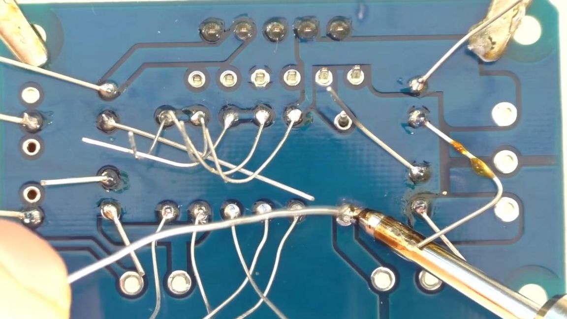
The remnants of the conclusions are removed using side cutters. When biting off the legs of the radio parts with side cutters, be careful, as you can tear off the board track.
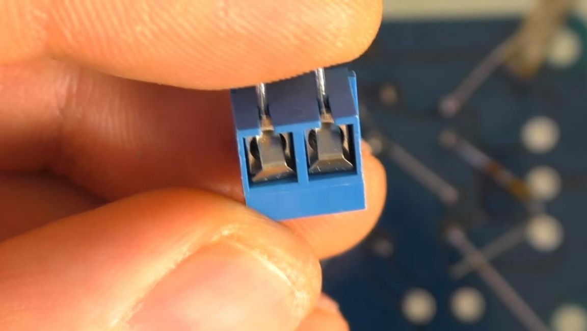
Next, to connect the power, input and output of the audio signal, install and solder the connectors.
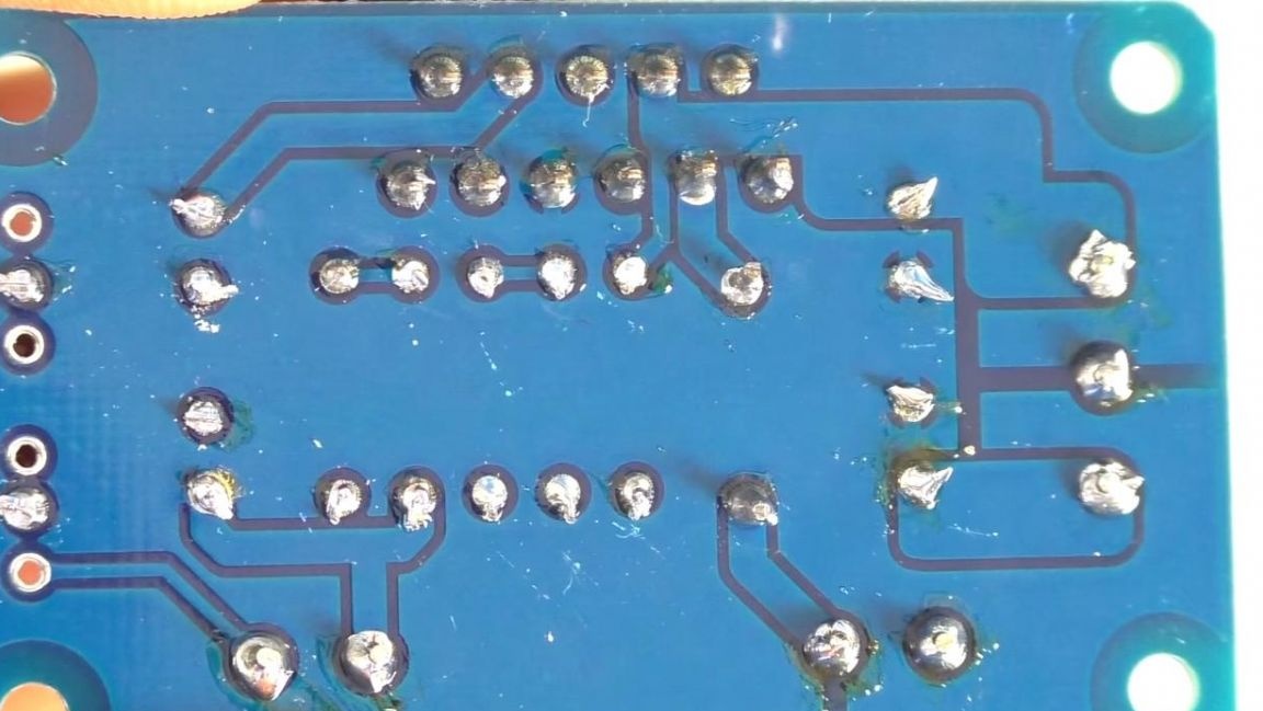
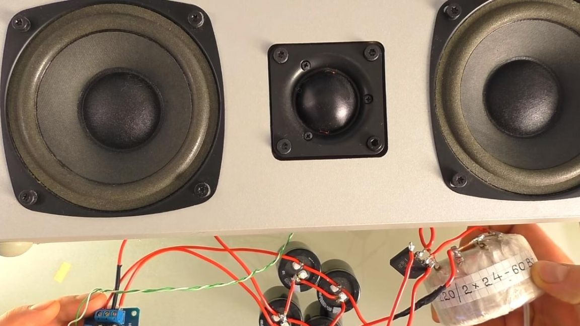
If soldering was carried out with flux, then the board must be washed from its residues using acetone or galosh gasoline. The low-frequency amplifier is completely ready, it remains to fix its chip on an aluminum radiator and test it. We connect wires to the power connector from the bipolar unit with a voltage of 24 volts, the sound will be input from the 3.5 mm jack, which must be connected to a playback device, for example, a telephone. The output signal from the amplifier is connected to the column, it is desirable to connect one speaker, since the amplifier has only a mono output.
The sound from this low-frequency amplifier is quite high-quality, has good bottoms and is great for assembling a home subwoofer or a car subwoofer with some modifications to the power supply.
That's all for me, thank you all for your attention and creative success.