
Hello to all lovers homemade. Probably everyone in the house has a clock that is very convenient to navigate in time, they usually weigh on a wall or stand on a table, cabinet, special shelf. But not always the watches that the manufacturer offers suit the end user, for this reason in this article I will talk about how to make a watch with a position and temperature sensor do it yourself, in the assembly of which the kit kit will help. A link to the radio designer will be at the end of the article, according to which you can order and re-assemble them at home.
Before reading the article, I propose to watch a video in which the entire process of assembling the clock is shown, as well as their check for operability.
In order to make a watch with a position and temperature sensor, you will need:
* Kit
* Soldering iron, flux, solder
* Silicone soldering mat
* 5V power supply
* Crosshead screwdriver
* Tweezers
* Copper braid to remove excess solder
Step one.
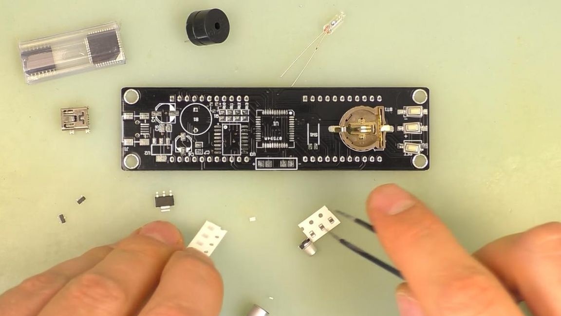
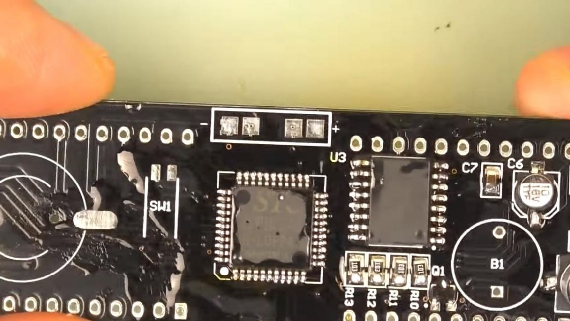
To begin, consider a set of radio constructor. There is a double-sided printed circuit board on which the components are marked, as well as for greater reliability, the holes for the radio components are metallized.
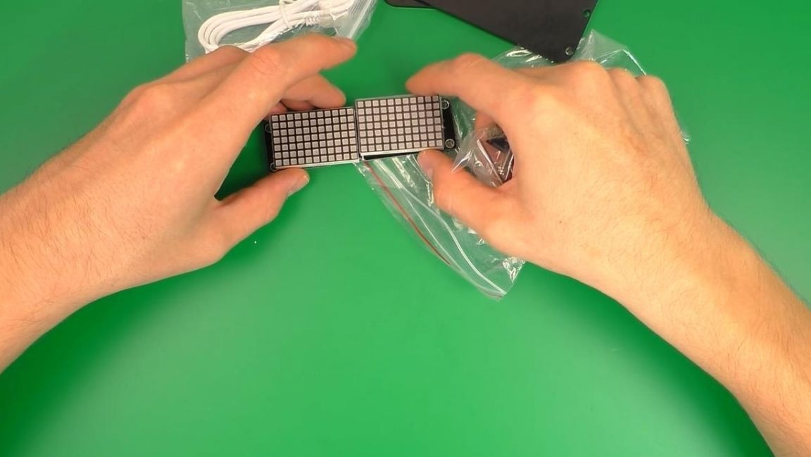
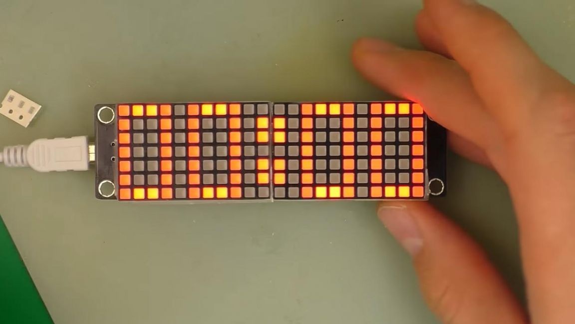
To connect the power supply, a cable is provided in the kit, on the one side of which there is a USB plug, and on the other, a Mini-USB, the voltage at the output of the power supply must be 5V. All information, including time itself, will be displayed on multi-segment indicators, there are two of them.
The remaining bag contains the entire set of SMD parts needed to assemble the watch. We proceed directly to the assembly process.
Step Two
Since SMD parts are small enough, they are easy enough to lose, so to prevent this from happening, pour them onto a silicone soldering mat, use tweezers for convenience.
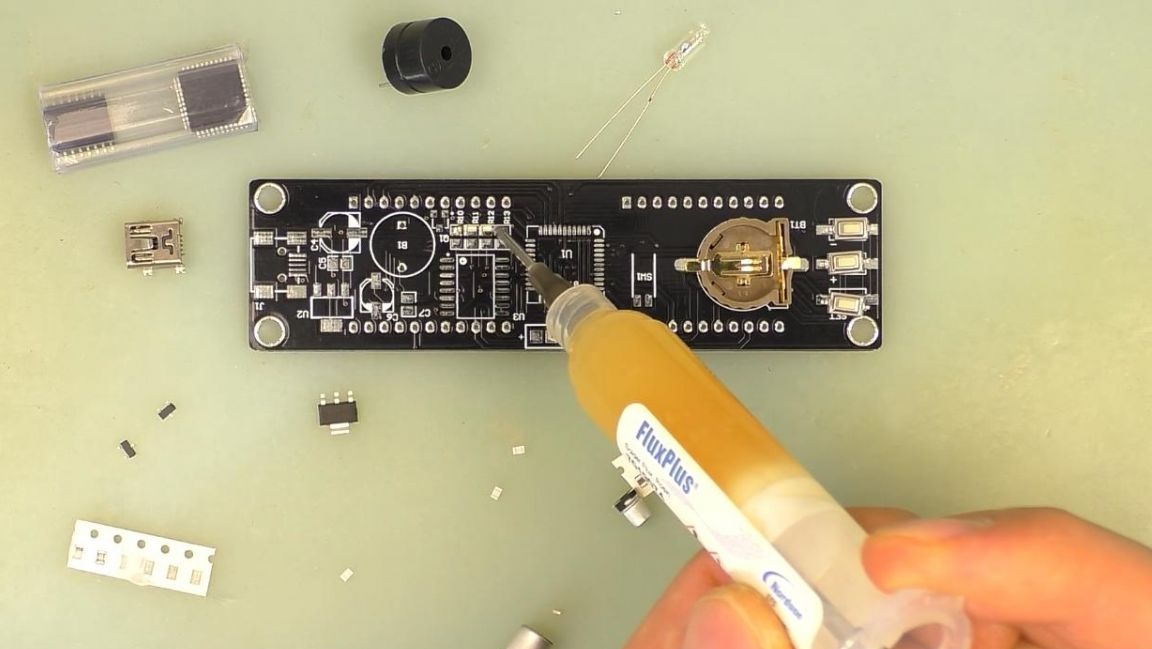
First, install the smallest elements on the board. We apply the flux from the syringe on one side of the contacts, after which we put SMD resistors on the contact pads and solder it to the tinned area using a soldering iron and solder.
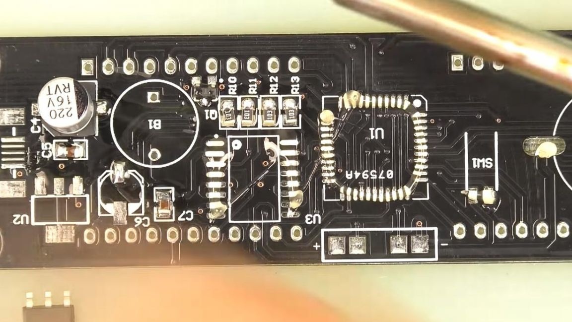
In this case, the resistors have the same resistance, so you do not need to determine their values. Next, we solder the transistor and ceramic capacitors in a similar way to the board, they also have the same ratings.Then we solder the electrolytic capacitors, which must be positioned so that their mark on the case in the form of a black strip coincides with the direction of the white semicircle on the board marking, we also pay attention to the dimensions of the case, since the ratings are different.
Step Three
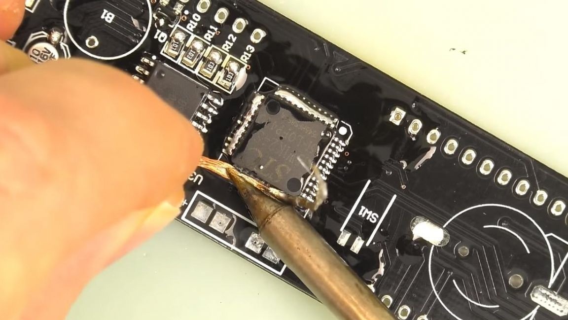
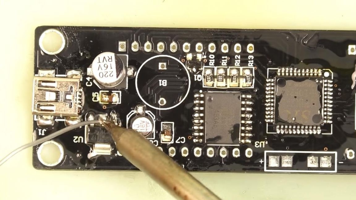
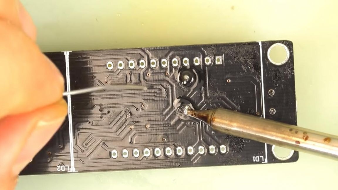
Now we apply the flux to the pads for the installation of microcircuits and solder them with a soldering iron and solder. The microcircuit needs to be arranged so that its key in the form of a point on the case coincides with the direction of the white point on the board. When soldering the terminals of microcircuits, try not to overheat them, as this can put them out of standing because of the high temperature.
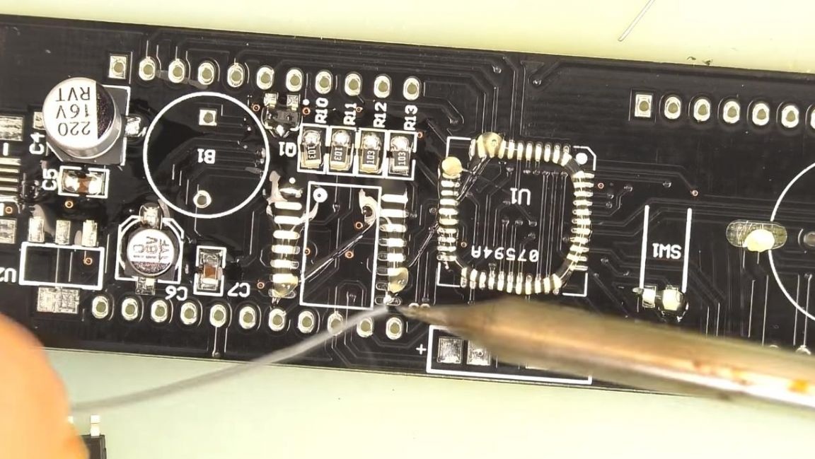
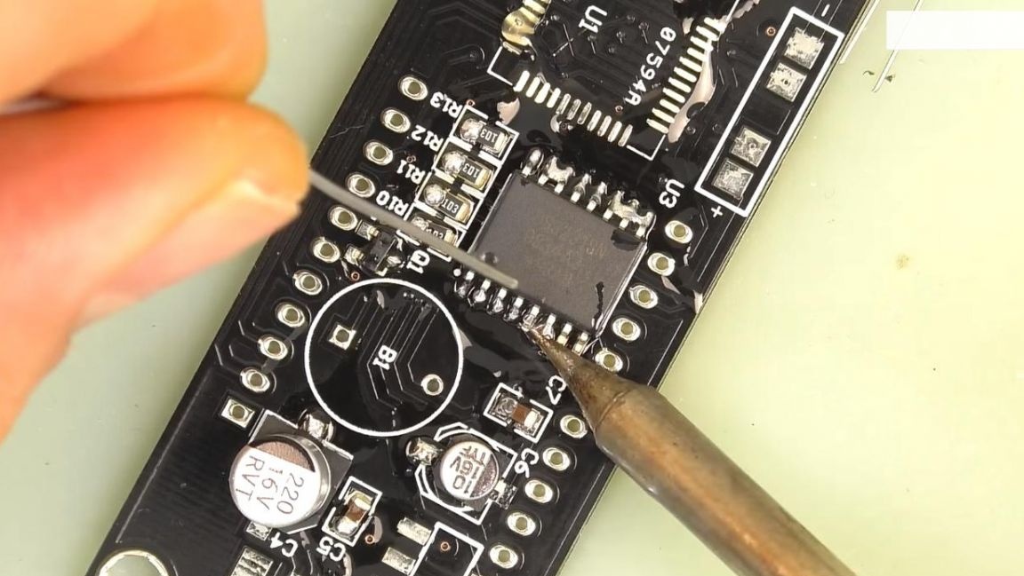
If the legs of the microcircuit are soldered together during the soldering process, this can be fixed with a copper braid, which absorbs excess solder.
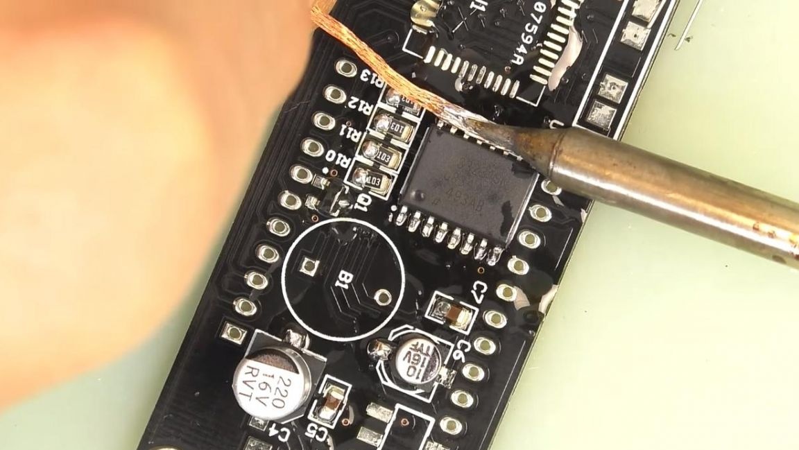
With the second chip we do the same.
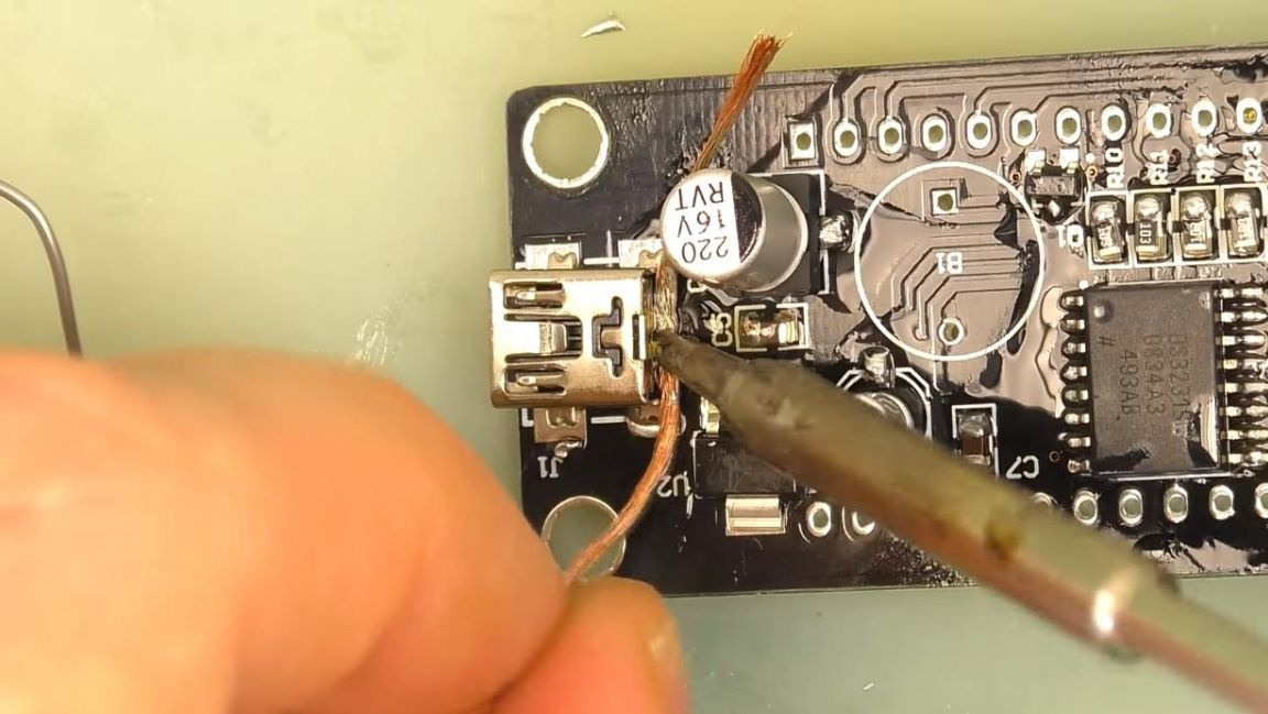
To connect the power, we solder the Mini-USB plug onto the board, its conclusions are very close, so when they are soldered together, we also use a copper braid.
Step Four
Since at the first stage only one contacts of the radio components were soldered, it is necessary to solder the remaining conclusions.
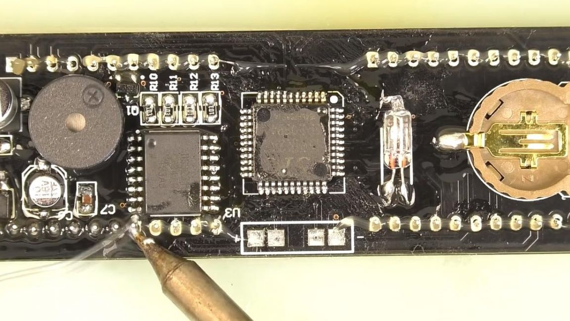
Next, solder the temperature sensor, and then three buttons, holding with tweezers for convenience. After installing the buttons, we install a battery slot on the board, in this case it serves to save all settings and time when disconnected from the power supply.
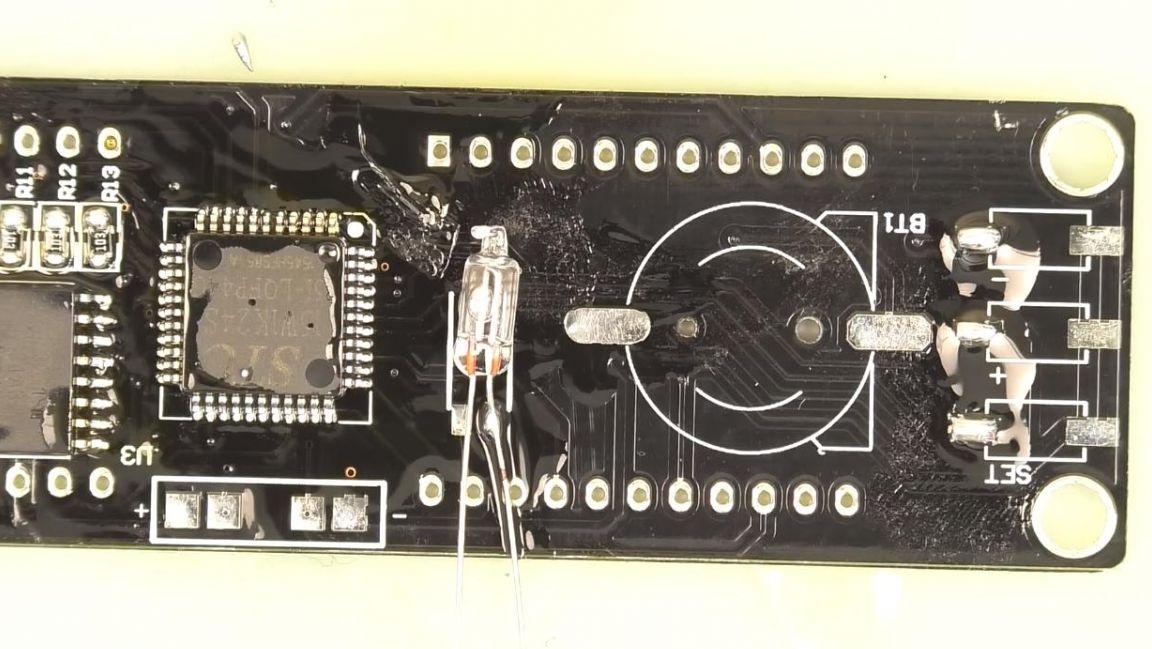
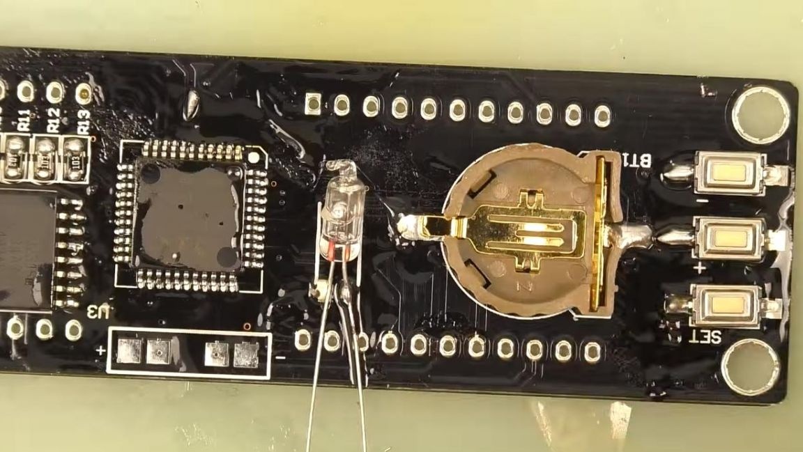
In order for the watch to work also as an alarm clock, insert the buzzer on the board and solder it, it has polarity, the positive output is the long leg, and on the board the plus is indicated by a square contact pad.
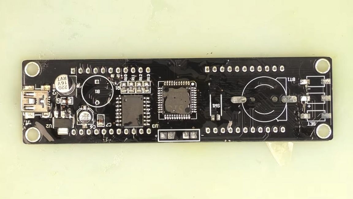
The last thing that will be soldered on the board is multi-segment indicators, of which there are only two. We install them in the holes on the board and solder the conclusions from the back.
After soldering, the flux itself can be washed off with acetone or galosh gasoline, but this does not necessarily and will not affect the operation of the board in any way.
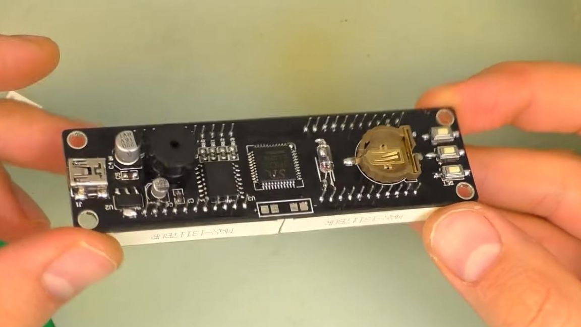
We check the board by connecting the power cable to the Mini-USB connector, the indicators work, the buzzer also, so you can collect everything in the case.
Step Five
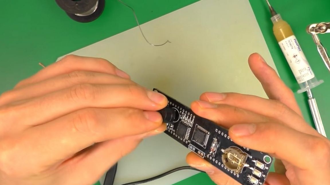
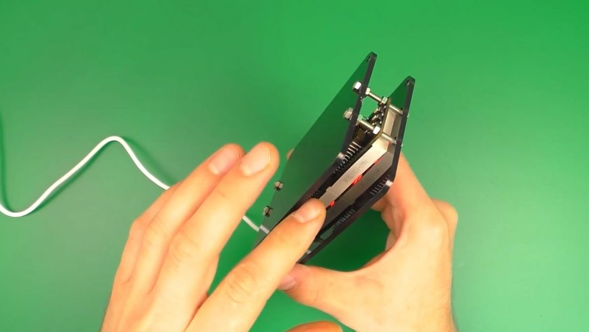
In order for the clock to be installed, for example, on a shelf, it is necessary to place the board in the case.
The case in this case is made of two plates made of darkened plexiglass, remove the protective film from the plates, and then fasten them to the board with a screwdriver on the screws with nuts.
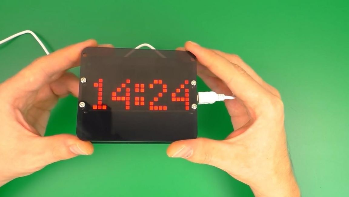
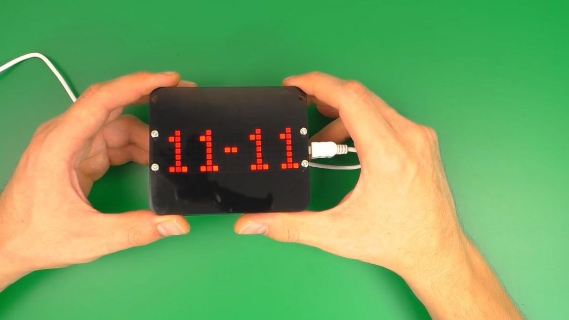
The watch is completely ready and shows both time, date and temperature, and if you turn them over, they will automatically flip the image, which you will not find in most watches.
That's all for me, thank you all for your attention and creative success.