
Here is the next stage of evolution, namely, the stabilized power supply on the SG3525 chip.
Up to this point, Roman, the author of YouTube channel “Open Frime TV”, made only the simplest power supplies on the IR2153 chip. Now the time has come for a more serious project. Immediately talk about the advantages of this scheme. The first, most important, is the stabilization of the output voltage. There is also a soft start, protection against short circuits and self-locking.

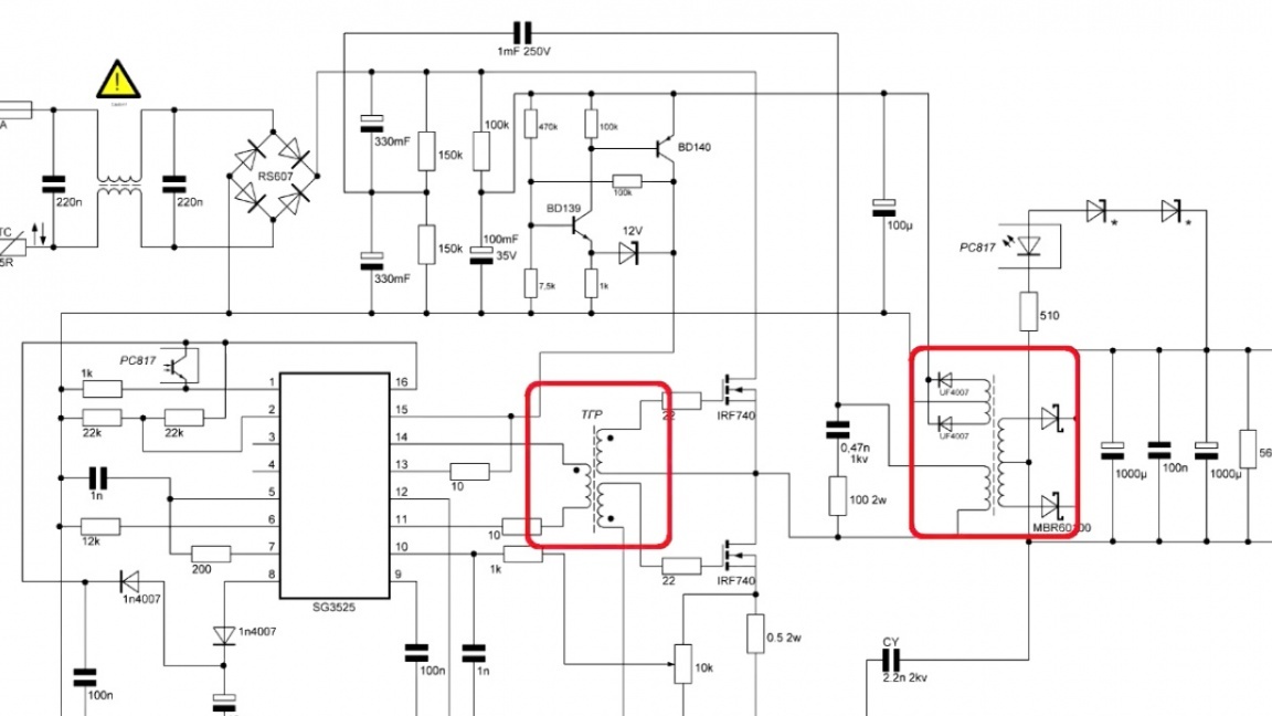
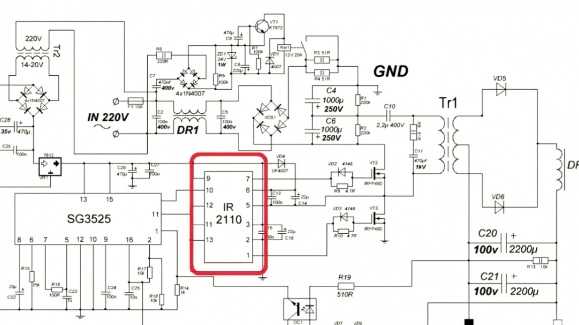
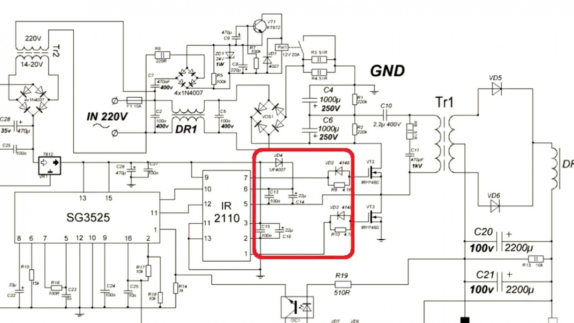
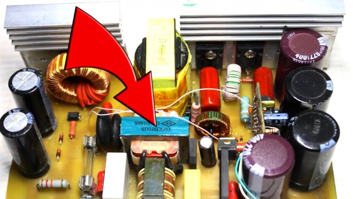
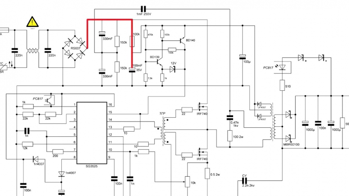
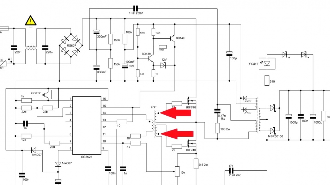
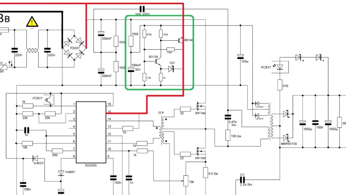
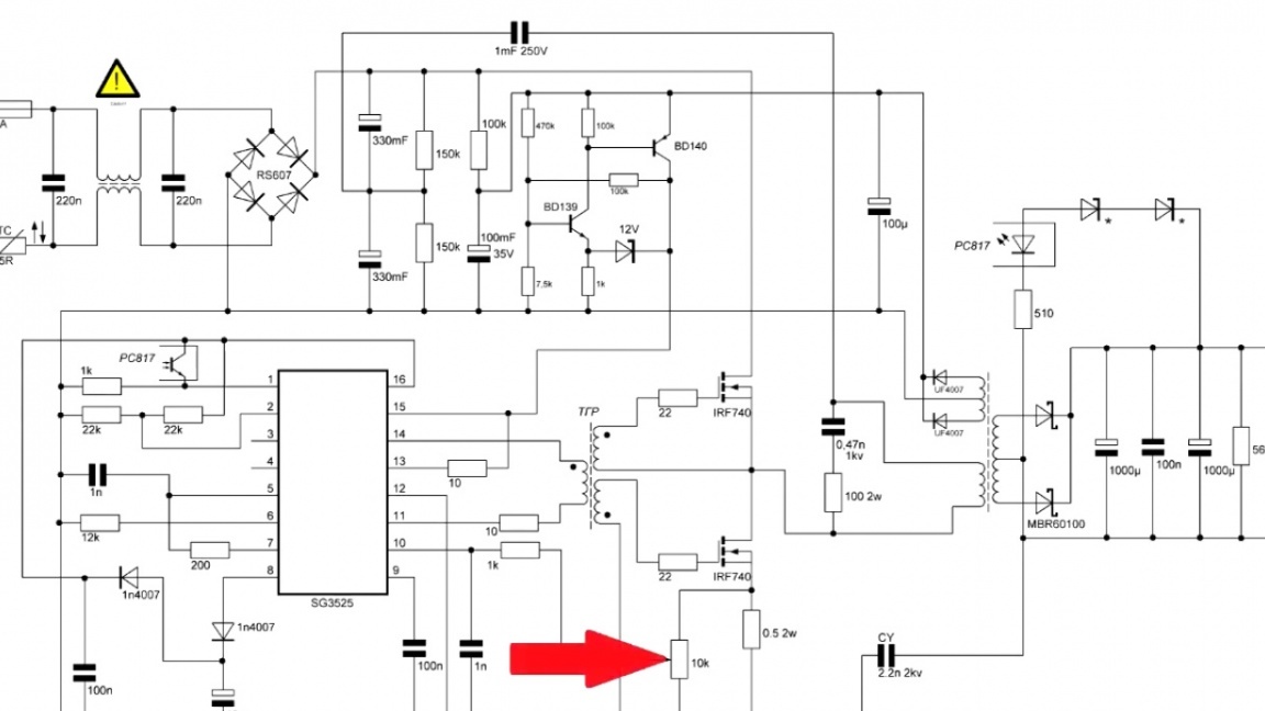
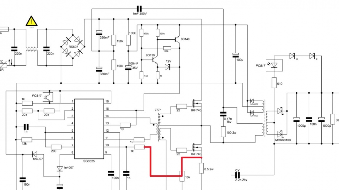
First, let's look at the device diagram.
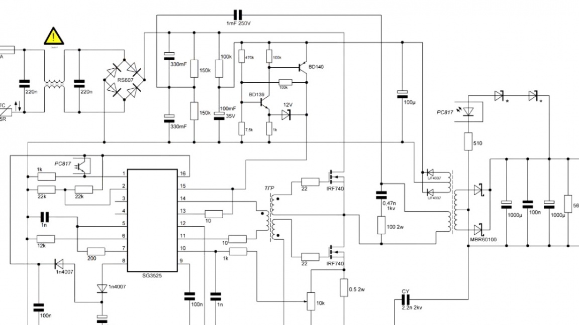
Beginners will immediately pay attention to 2 transformers. In the scheme, one of them is power, and the second for galvanic isolation.
Do not think that because of this, the scheme will become more complicated. On the contrary, everything is becoming easier, safer and cheaper. For example, if you put a driver at the output of the microcircuit, then you need a strapping for it - this time. And secondly, its price is about 2 dollars.
We look further. In this scheme, microstart and self-locking are implemented.
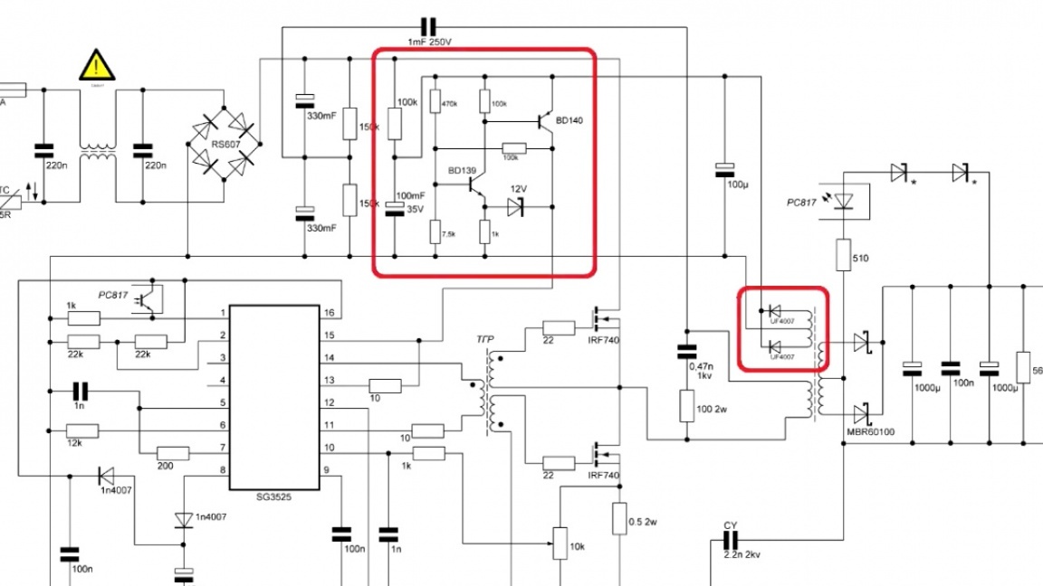
This is a very productive solution, it eliminates the need for a standby power supply. Indeed, making a power supply for a power supply is not a good idea, and such a solution is simply perfect.
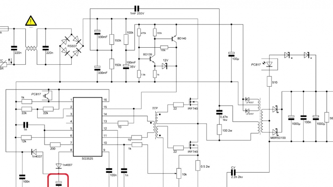
Everything works this way. A capacitor is charged from a constant and when its voltage exceeds a predetermined level, this unit opens and discharges the capacitor to a circuit.
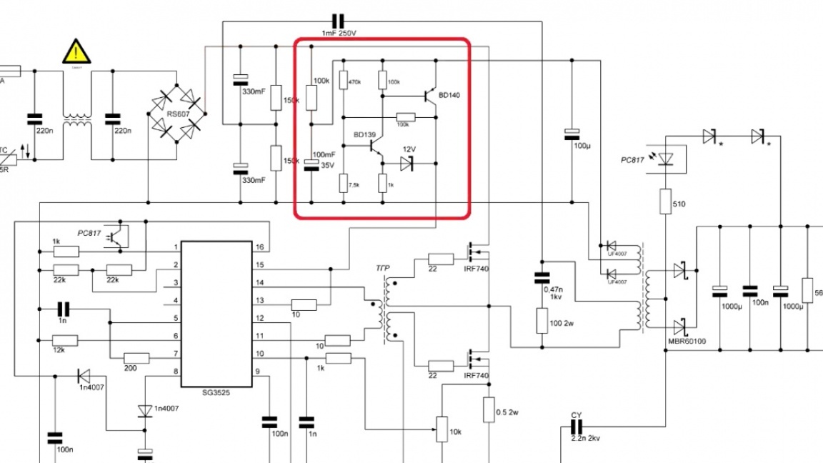

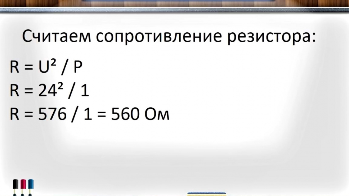
Its energy is enough to start the microcircuit, and as soon as it started, the voltage from the secondary winding began to power the microcircuit itself. It is also necessary to add this output resistor to the microstart, it serves as a load.

Without this resistor, the unit will not start. This resistor is different for each voltage and it is necessary to calculate it from such considerations that at the rated output voltage 1W of power is dissipated on it.
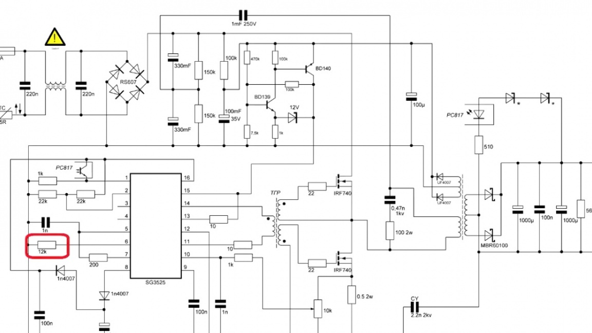
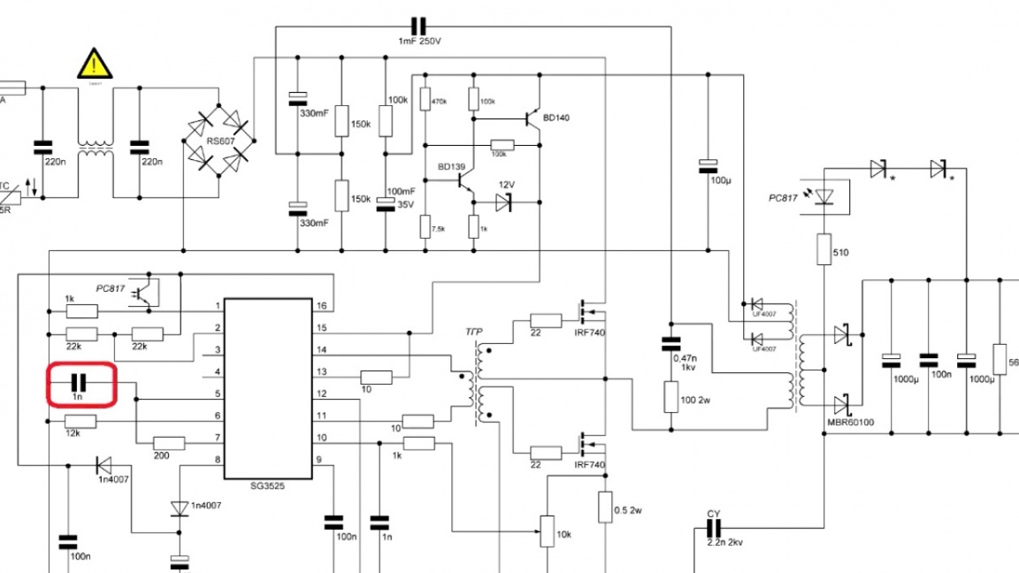
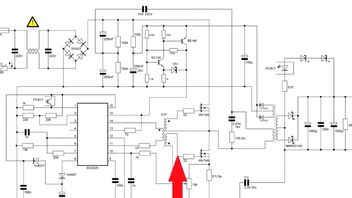
Also on the diagram is a soft start. It is implemented using this capacitor.
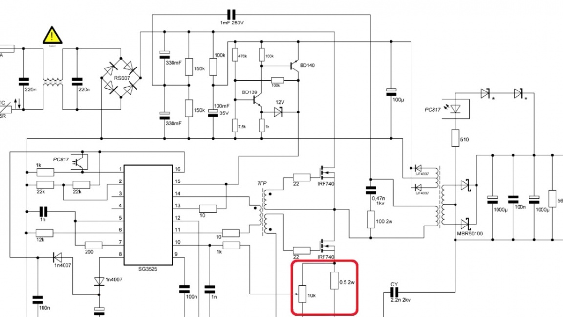
And current protection, which in the event of a short circuit will begin to reduce the width of the PWM.
The frequency of this power supply is changed using this resistor and Conder.
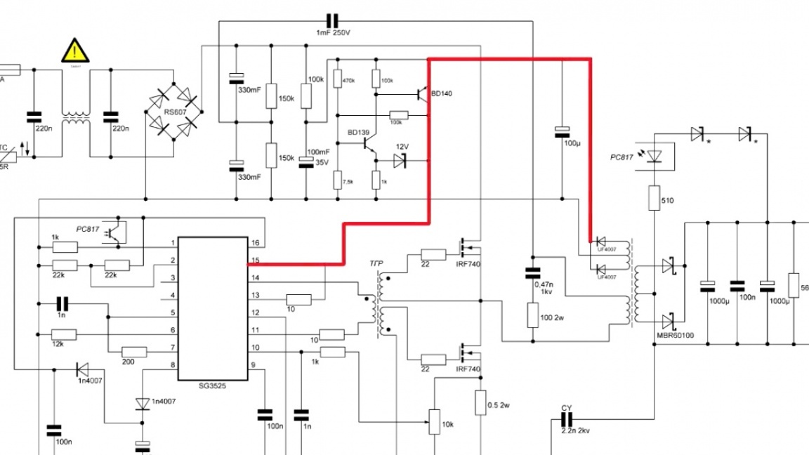
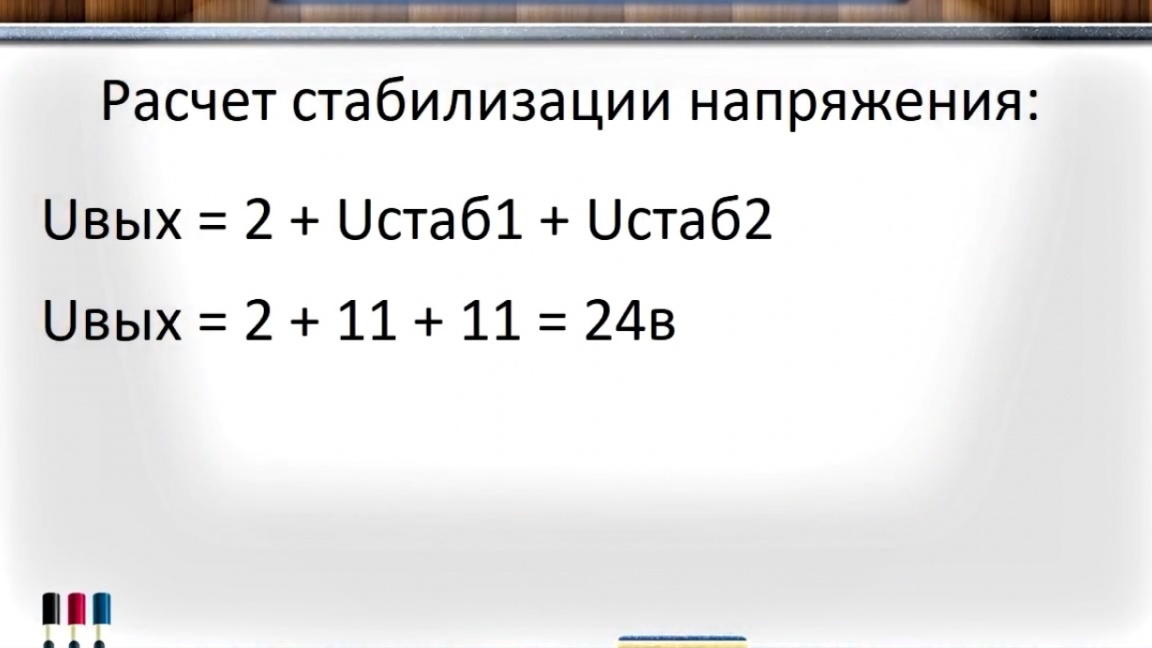
Now let's talk about the most important thing - this is the stabilization of the output voltage. These elements are responsible for it:
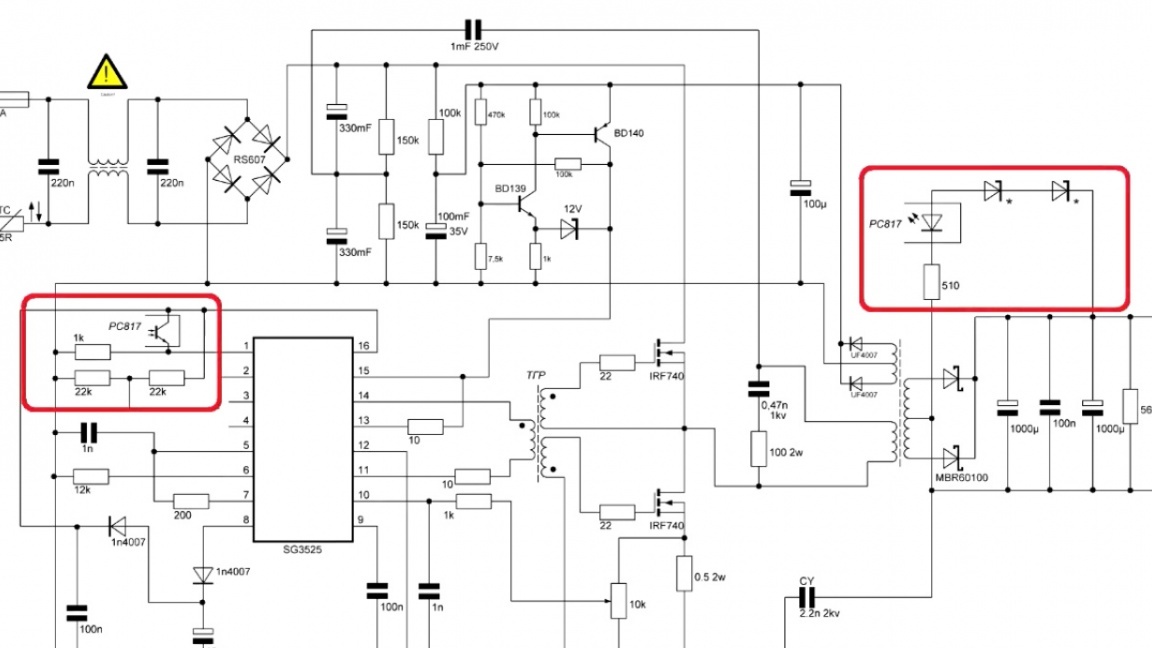
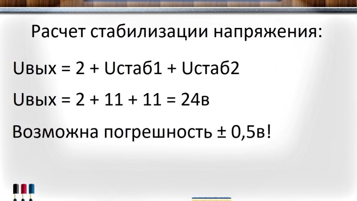
As you can see, the author put 2 zener diodes. Using them, you can get any voltage at the output.
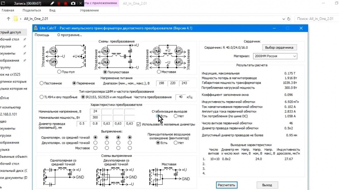
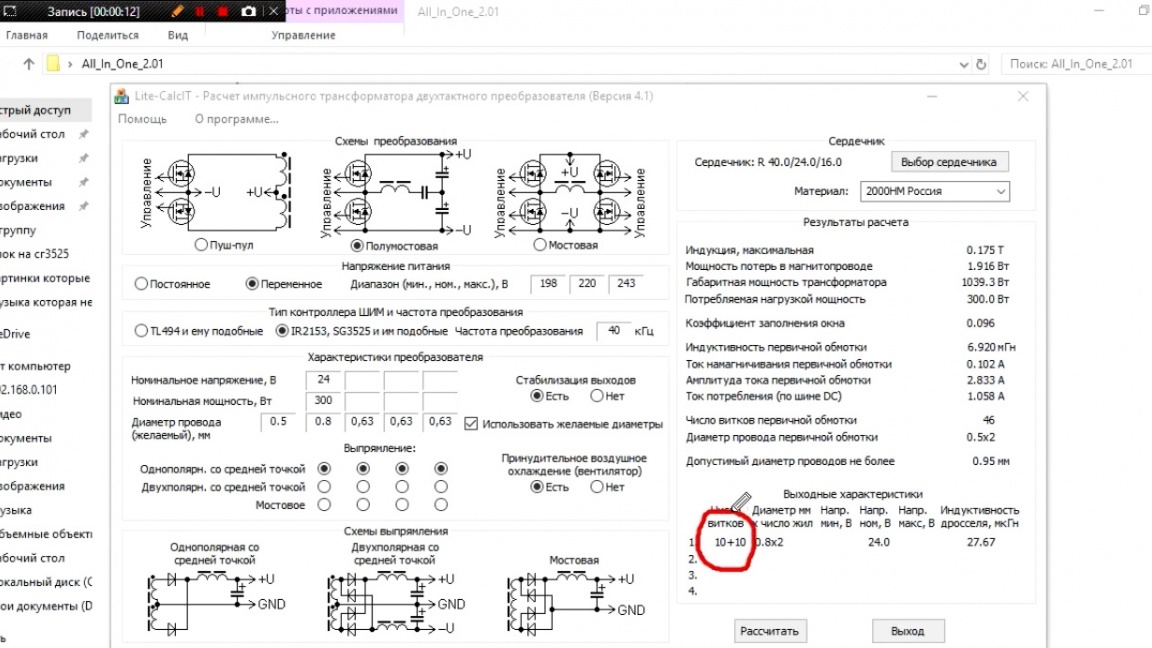
In order for stabilization to work correctly, you need a voltage margin in the transformer, otherwise, with a decrease in the input voltage, the microcircuit simply can not produce the desired voltage. Therefore, when calculating the transformer, you should click on this button and the program will automatically add you the voltage on the secondary winding for the reserve.
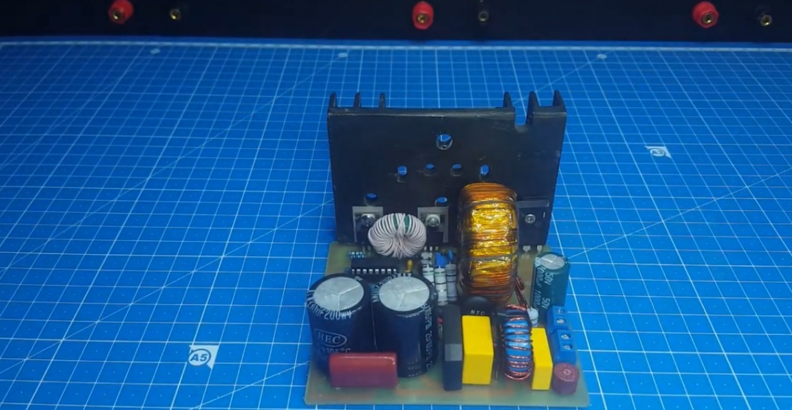
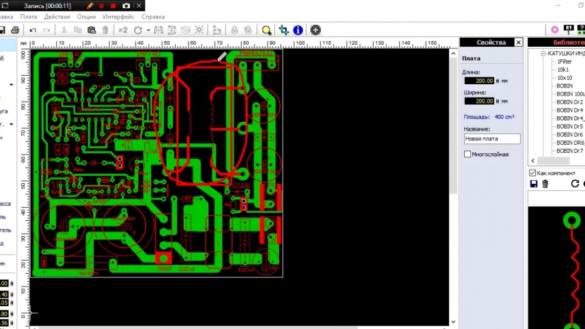
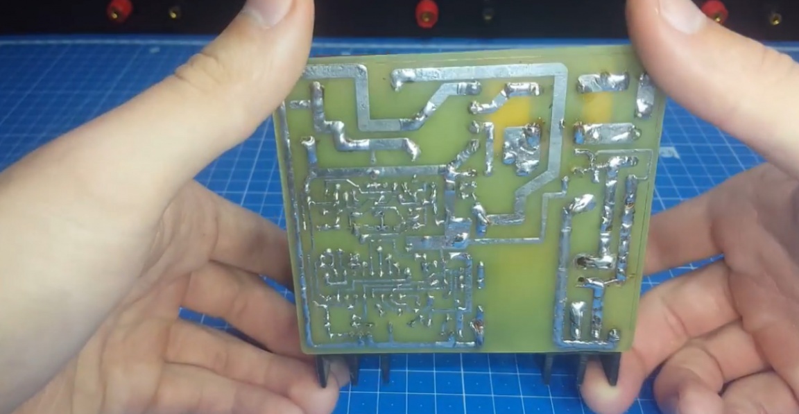
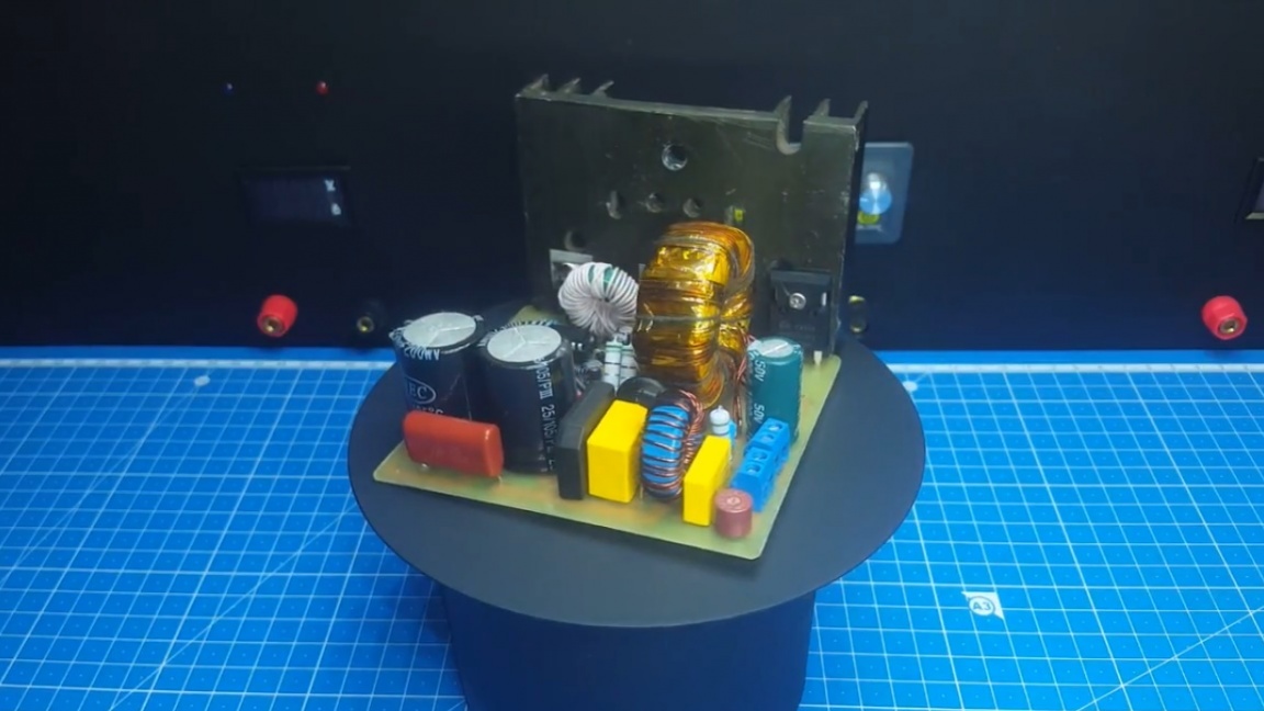
Now we can proceed to the consideration of the printed circuit board. As you can see, everything is pretty compact here.
We also see a place under the transformer, it is toroidal. Without any problems, it can be replaced with a W-shaped.
The optocoupler and zener diodes are located near the microcircuit, and not at the output.
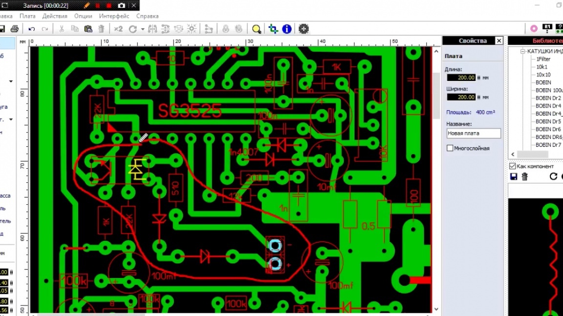
Well, there was nowhere to put them on the way out. If you do not like it, do your PCB layout. The author claims that everything works so well.
You may ask, why not increase the fee and make everything normal? The author’s answer is as follows: this was done so that it would be cheaper to order a board in production, since boards larger than 100 by 100 mm are much more expensive.
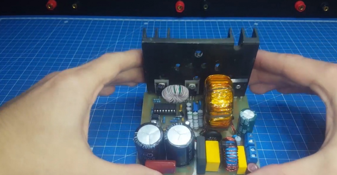
Well, now is the time to put together our circuit. Everything is standard here. We solder without any problems. We wind the transformer and install it.

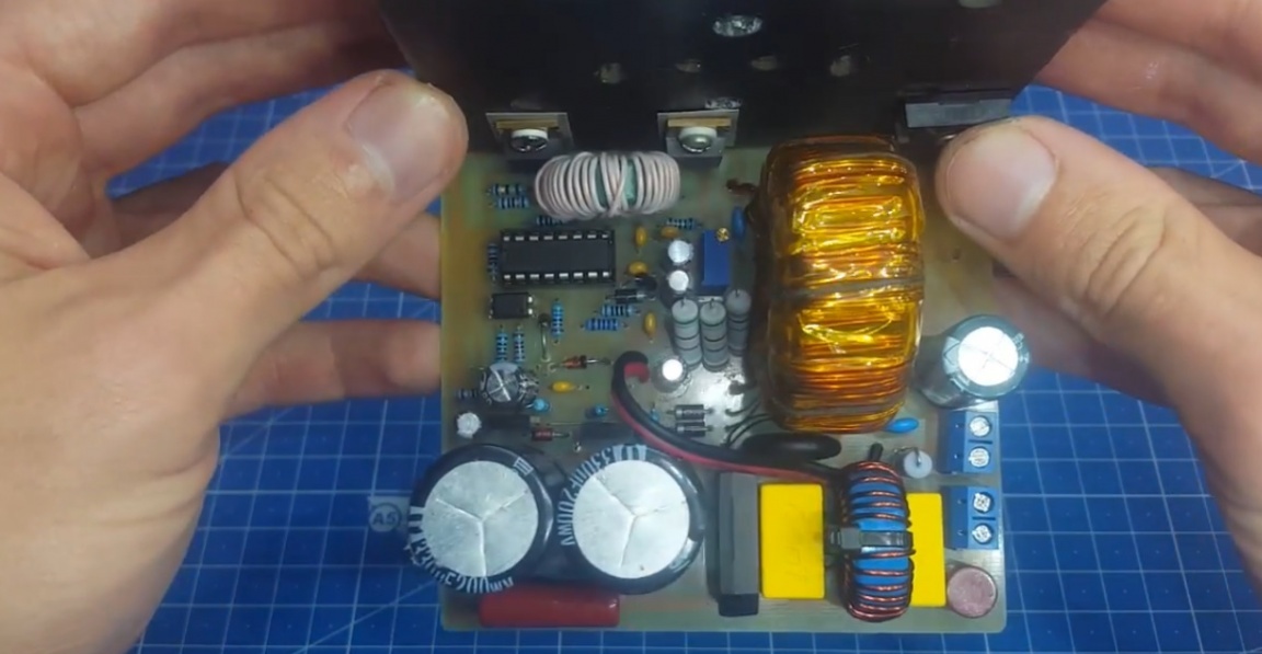
The author admits that at first he thought that this project would be a failure. Such thoughts came after he made the layout, and constant jambs appeared. This is what the prototype looked like, some kind of hedgehog.
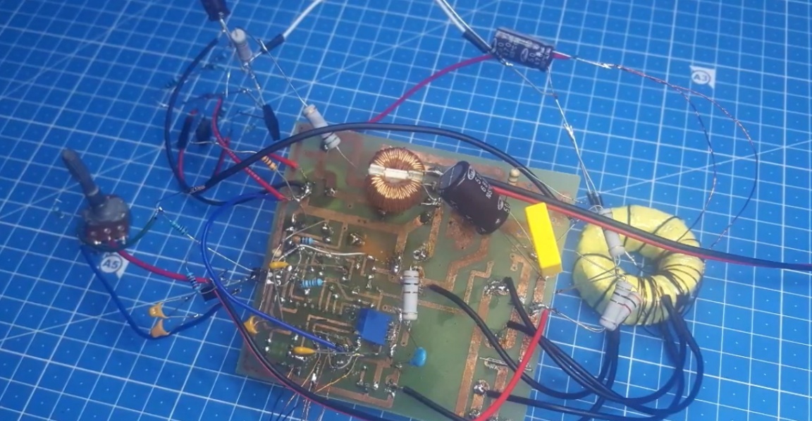
But everything worked out thanks to Yuri, the author of YouTube channel “RED Shade”, which helped to solve several important points of this project.
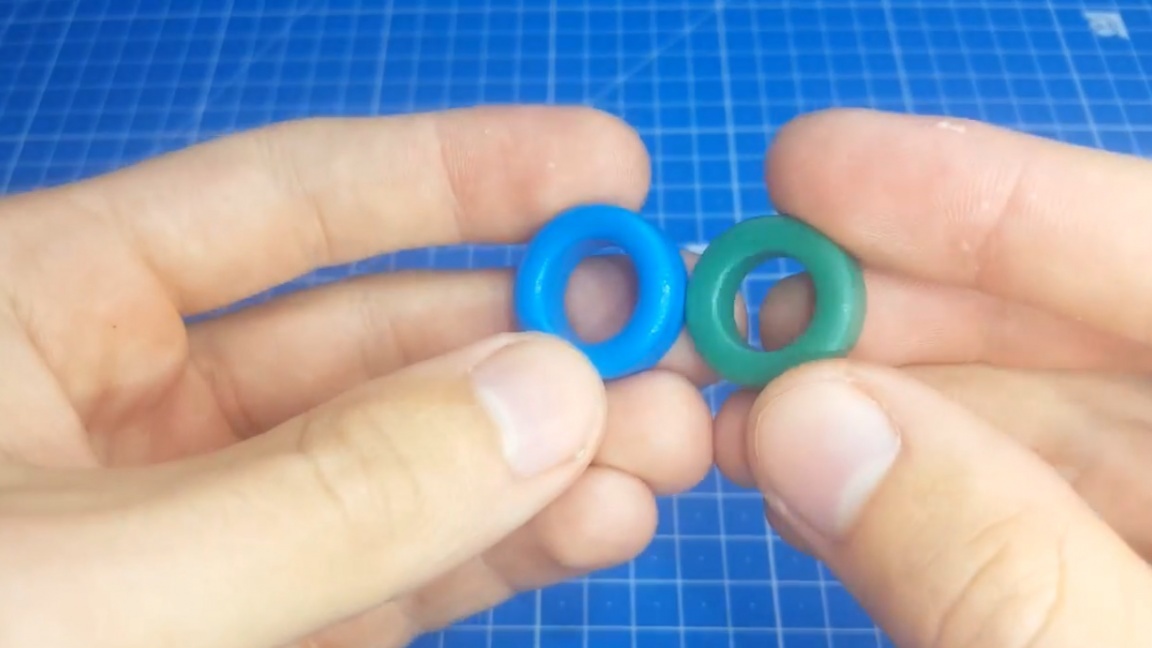
It is also worth paying attention to certain important points. These include the input choke. It can be wound on a core with a permeability of 2000 nm, sizes 20 by 13 and 7 mm.
It is advisable to separate the windings into 2 parts. For insulation, ordinary plastic screeds are used. We wind with a wire of 0.8 mm. The number of turns of each winding is 10-13.
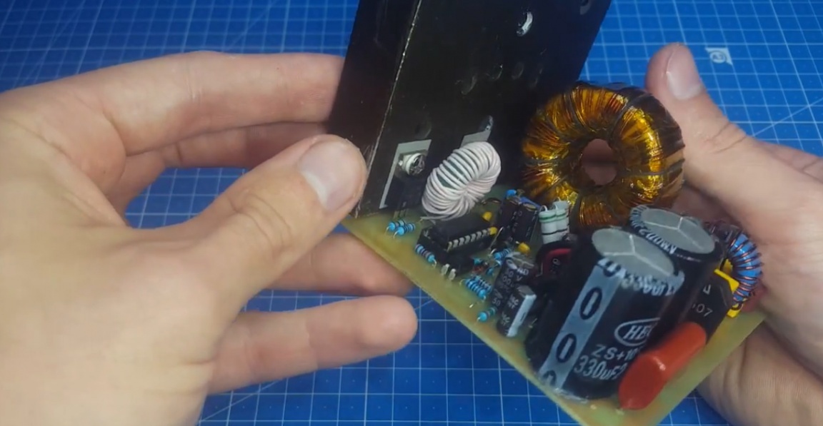
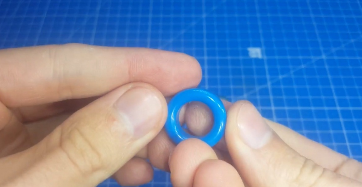
And now the worst part of the scheme is the TGR.
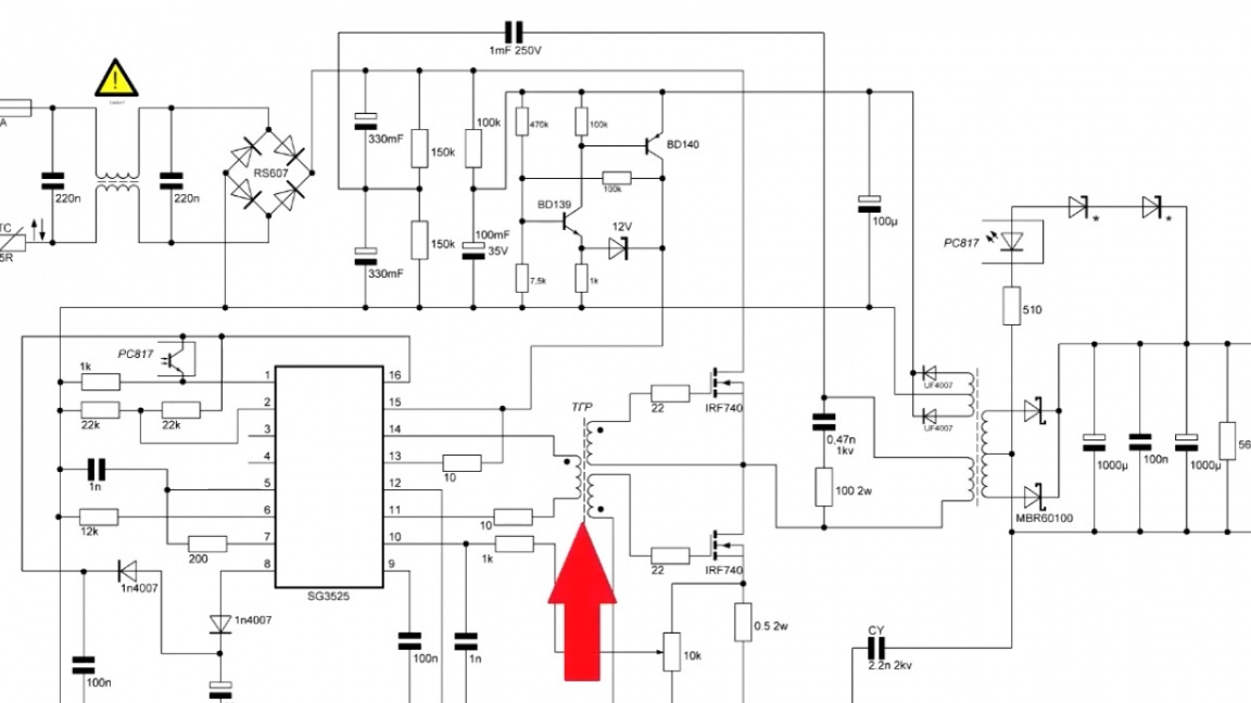
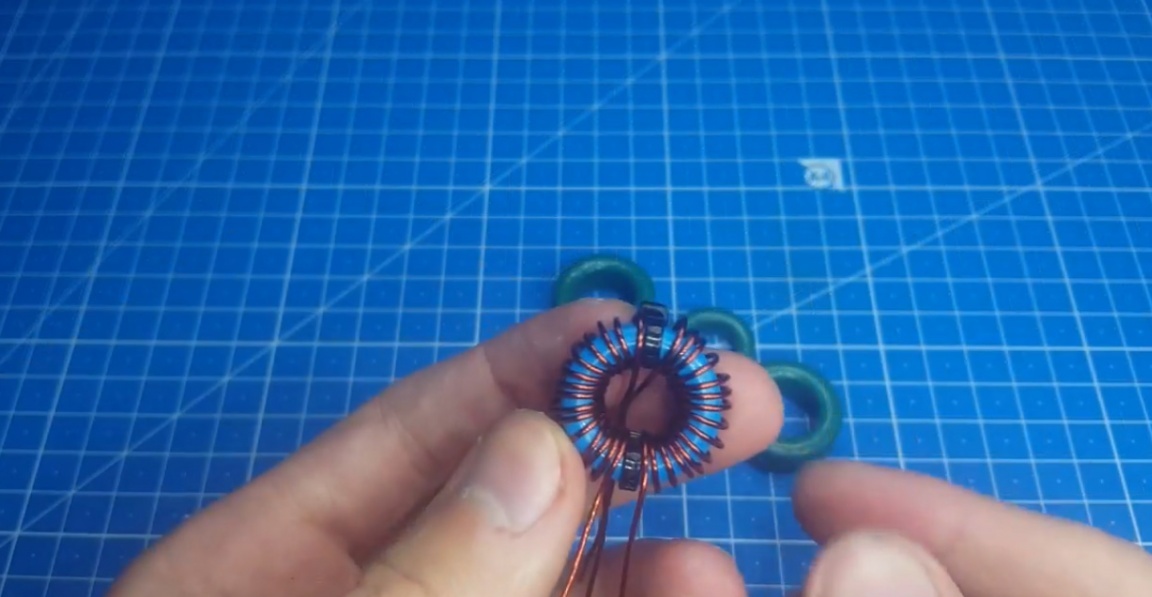
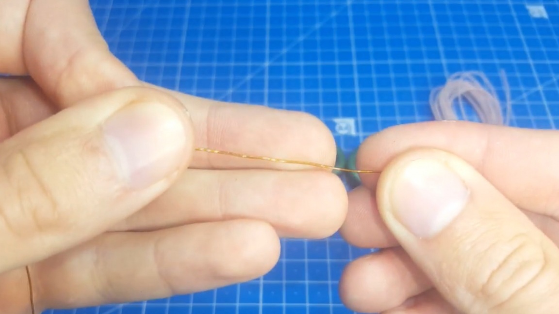
In fact, it is no heavier than a throttle. We take a ring with a permeability of 2000 Nm, the dimensions are the same as that of the throttle, it can be smaller, this is not critical, and we wind 3 wires with MGTF wire 20 turns.
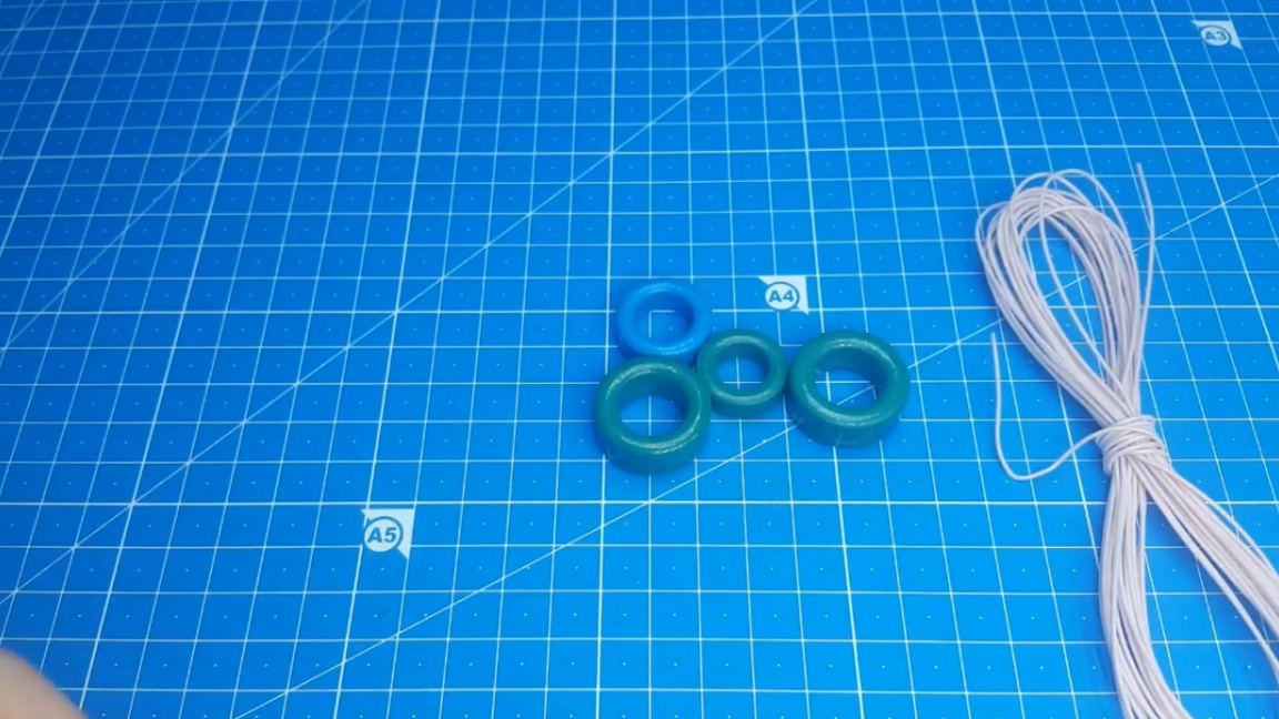
There is no such wire - it does not matter, you can use ordinary enameled wire with a diameter of 0.4-0.6 mm.
And that's it, TGR is ready.
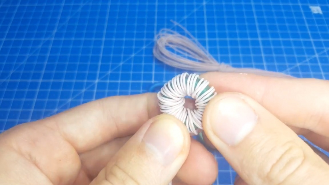
The only thing where you need to be careful is when installing it on a board. Observe phasing! The output windings are turned on counter - this is important.
It should also be shown what happens at the gates of transistors. This is for those who have an oscilloscope.

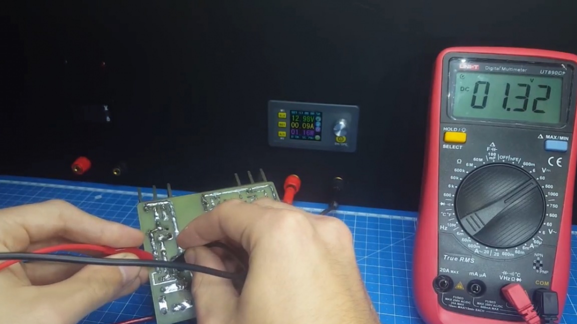
As you can see a fairly clear signal. He is a bit overwhelmed, but this does not affect the work. Well, that’s all the information about the block. The first inclusion is preferably made from a low-voltage power supply by disconnecting this circuit and supplying 12V simultaneously to both power and control.
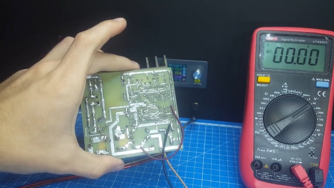
Check the output voltage. If it is present, then it can already be included in the network.
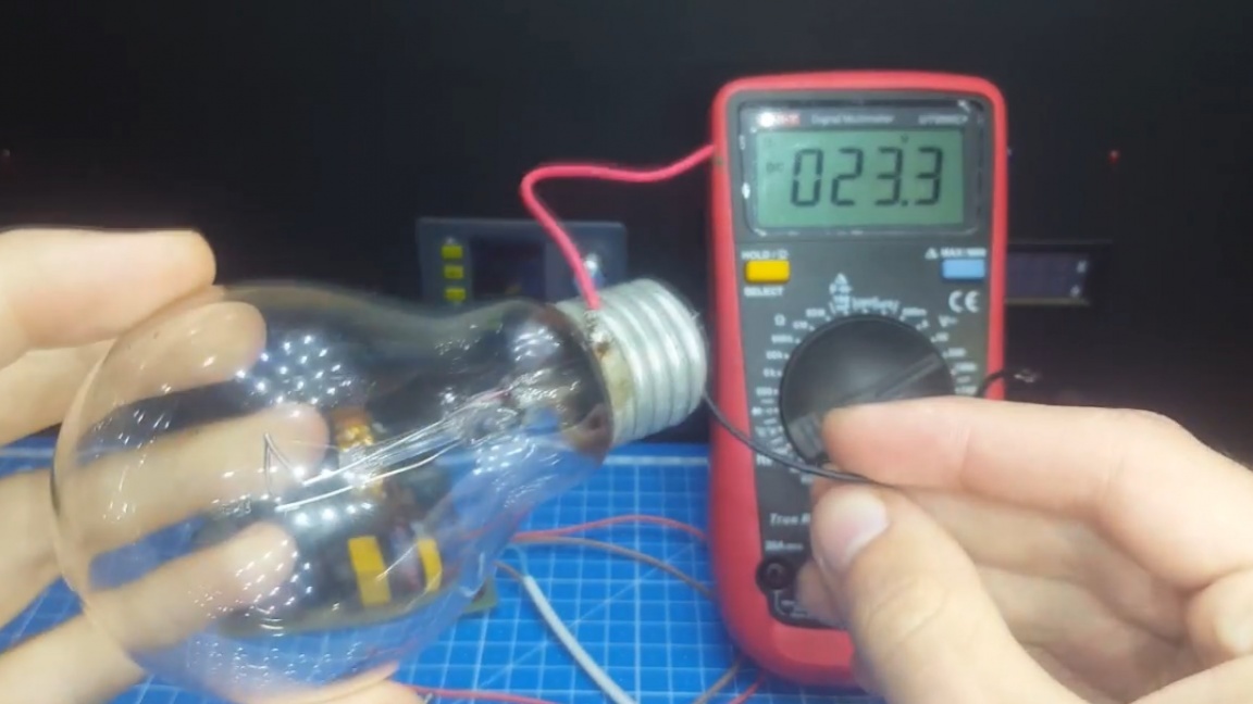
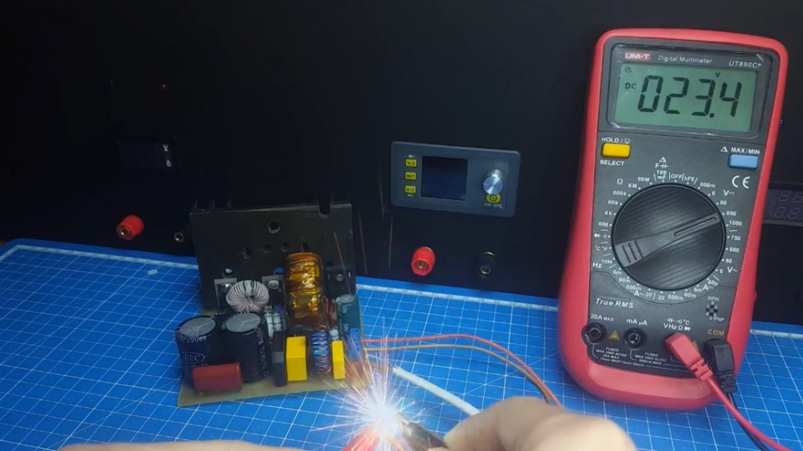
First, check the output voltage. As we see the block, the author was counting on a voltage of 24V, but it turned out a little less due to the spread of the zener diodes.
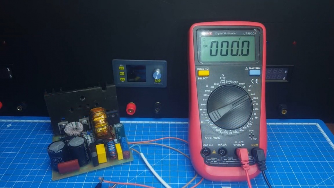
But such an error is not critical. Let's check the most important thing - stabilization. To do this, take a 24V lamp with a power of 100W and connect it to the load.
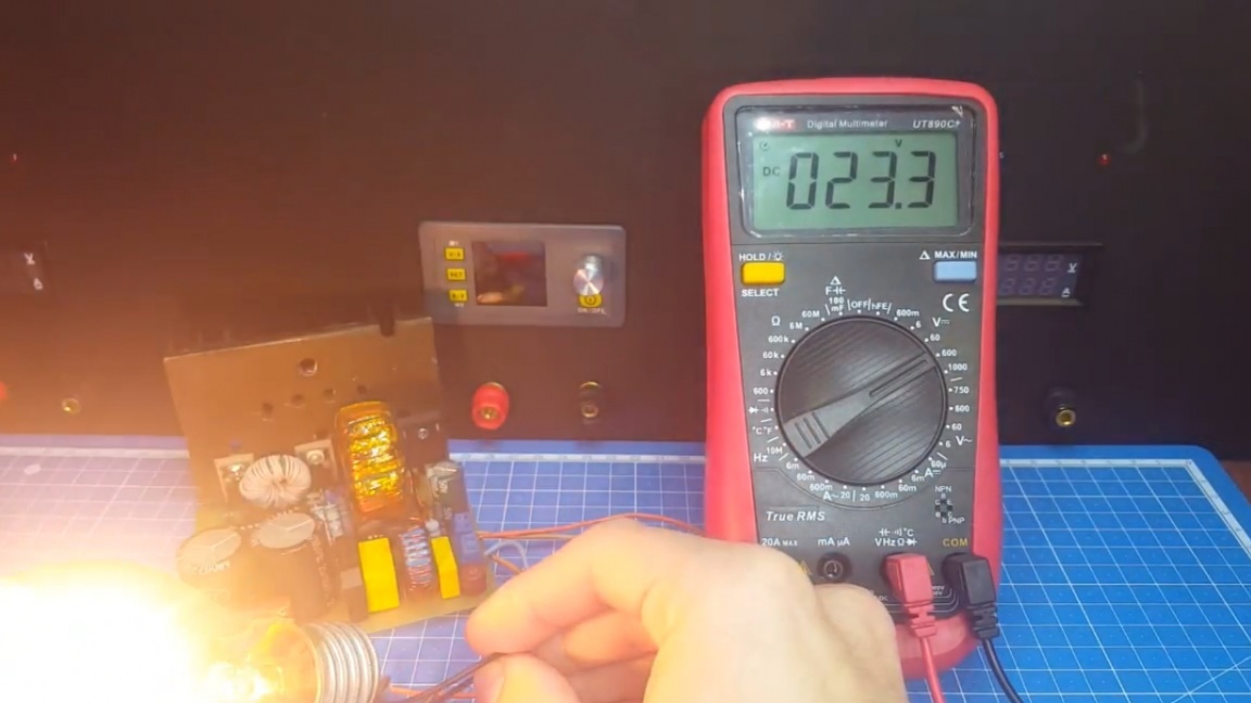
As you can see, the voltage did not subside and the unit withstood without problems. You can load even harder.
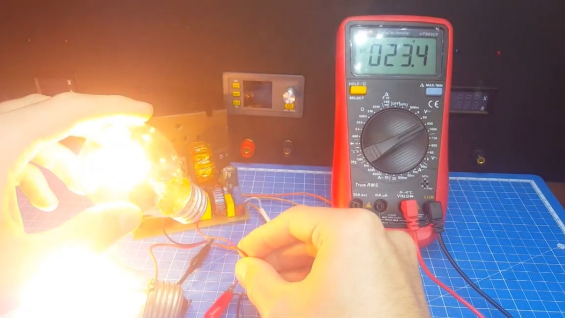
As we see the result is the same, the voltage is stable. We also check the protection against short circuit.
To do this, unscrew the resistor to the upper position and short the conclusions.
Fuh, nothing exploded and the block saved itself. Well, now, by adjusting the value of the resistor, you can select any short-circuit current limiting to your needs. In the end, I would like to discuss a couple of important points. Firstly, the author does not recommend increasing the power of this unit above 500W, and secondly, in the description under the original video of the author (link SOURCE), you will find a link to the video about this chip that the author used to create this project.
That's all. Thank you for attention. See you soon!
Video: