The vertical amplifier module, proposed by the author of Instructables under the nickname erik_montesdeoca, can save a lot of space on printed circuit boards, as well as on prototypes like breadboard and breadboard. However, as part of circuits performed by volumetric installation, it will work no worse. The module is connected with a comb with only four pins (the cat has four legs: input, output, earth and power, but you can’t touch it - it will close), and there is already a capacitor after the output. Here are two main areas of application. homemade:
1. Any designs where a low-power amplifier is required: portable speakers, doorbells ...
2. If, where you live, there are a lot of medium-wave radio stations, such as in St. Petersburg (hi, Yunost.Ru channel!), Such an amplifier can be connected to a detector receiver loaded with a 10-100 kOhm resistor. Without a resistor it will wheeze. This is a great solution for those wishing to experiment with detector receivers, but not having the ability to make an external antenna, grounding. A three-meter piece of wire is enough.
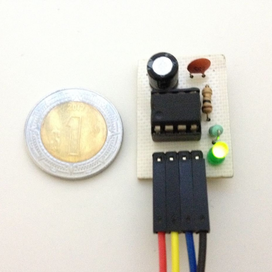
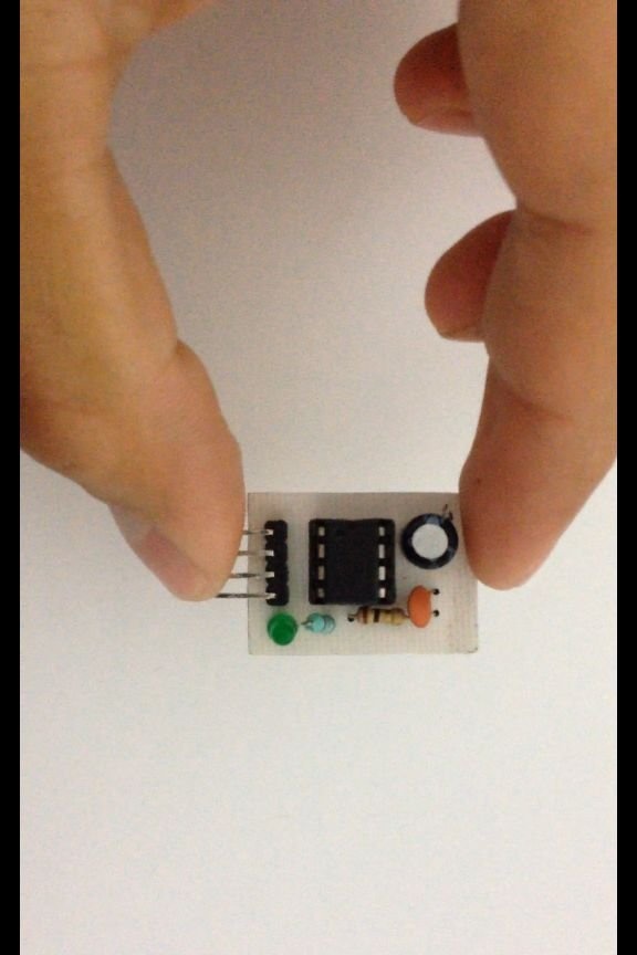
The photo below shows all the components of the module: the LM386 chip itself, a socket (only for those who are afraid of overheating the chip), comb, electrolytic capacitor at 220 μF, 25 V, ceramic capacitor with a capacity of about 0.05 nF, 10 ohm resistor. If you want a LED on the module, you will also need it, as well as a resistor from 220 Ohms to 1 kOhm. The module board can be made LUT, or you can take a piece of breadboard type perfboard. About it below.
In the datasheet, the circuit for switching on this chip is as follows (the supply voltage is about 6 V, the voltage gain is about 20):
But, of course, the master will not put the variable volume control resistor directly on the module. He got such a scheme:

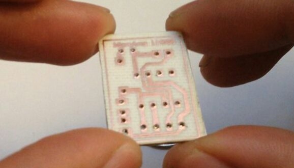
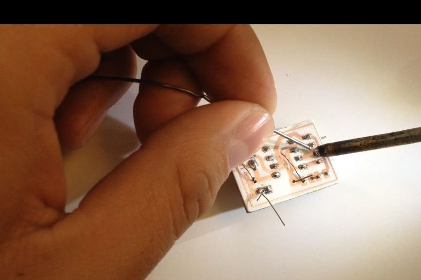
As mentioned above, the master made the module board by LUT:
Collected:
Done:
If you also choose LUT, the necessary files here.
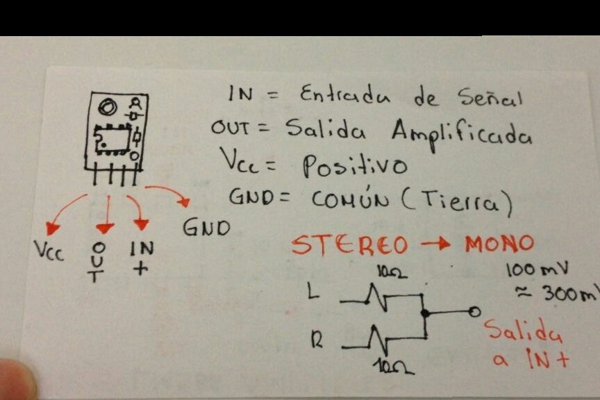
With this topology, the comb pinout is as follows: plus power, output, input, common wire (seephoto, it also shows a way to convert stereo to mono for those who have collected only one such module)
Video on YouTube under CC-BY:
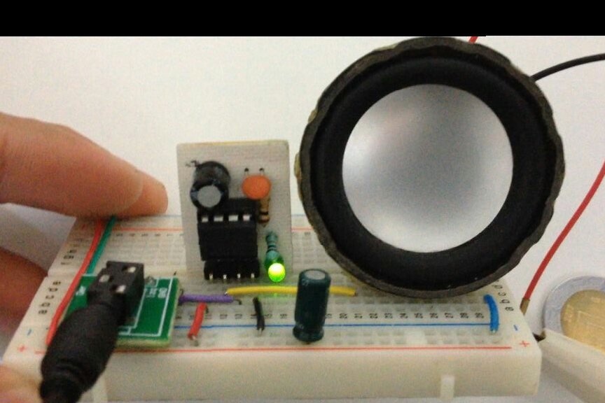
And this photo shows how convenient it is to put such a module on a breadboard like breadboard: