

Hello, friends the inhabitants of our site! Many of you have encountered such a problem as the burnout of the brake lights. And we will find out about this much later than we would like. I usually check the brake lights when leaving the garagebut in a hurry sometimes you forget about them. Upon arrival home, you find that one of the lamps is off. It’s good that there are two of them, and if both lamps burn out at once, then certainly with sharp braking they can enter you from behind and quite strongly. And you will be to blame for this.
I bring to your attention home-made, which will check for you the performance of the brake lights.
Here is a homemade scheme
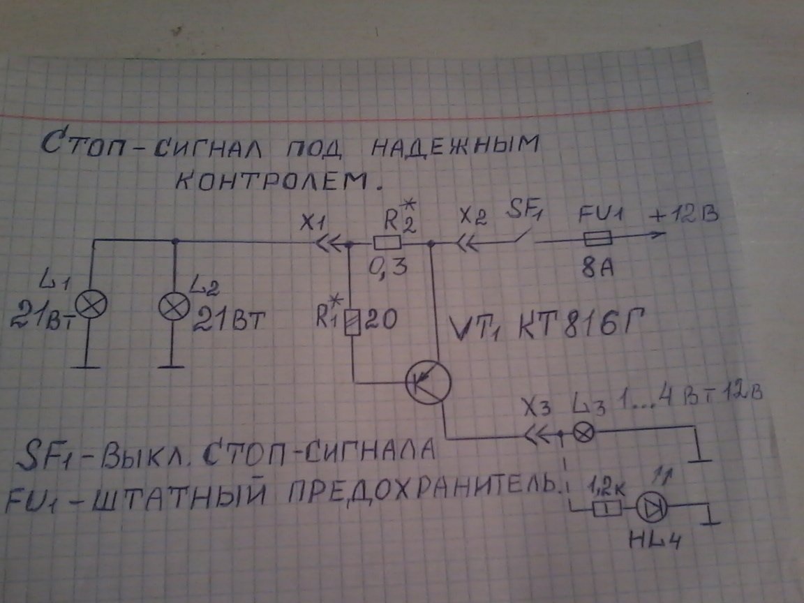
She was taken by me from the Internet. Instead of the L3 bulb, I put a red LED, its connection is shown by dashed lines. The LED is installed on the instrument panel or in a convenient place. When you press the brake pedal, the brake lamps light up and the LED lights up with them, informing the driver about their serviceability. If one of the lamps burns out or there is a bad contact in the lamp holder, the LED will not light. The same thing will happen if both lamps burn out. The LED will turn on only if Ur2 - the voltage at resistor R2 - exceeds the cut-off voltage of the silicon transistor VT1. at R2 = 0.3 ohms and the total current in the stop lamps I = 3.5 A (actually a little less due to the voltage drop across the resistor R2).
To assemble the homemade product, we need the following parts and tools
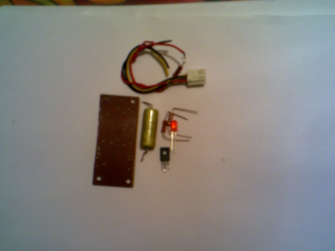
1 - transistor KT816G; MLT resistor -0.25 W 20 ohms; Resistor 0.3 ohm wire or finished C-5 -16v-5 w 0.33 ohm; one LED, any red; 0.5 watt resistor 1.2 kΩ, for connecting an LED.
2 - printed or circuit board; mounting wires; tweezers; soldering iron; solder; nippers; pliers. We assemble as follows.
Step 1
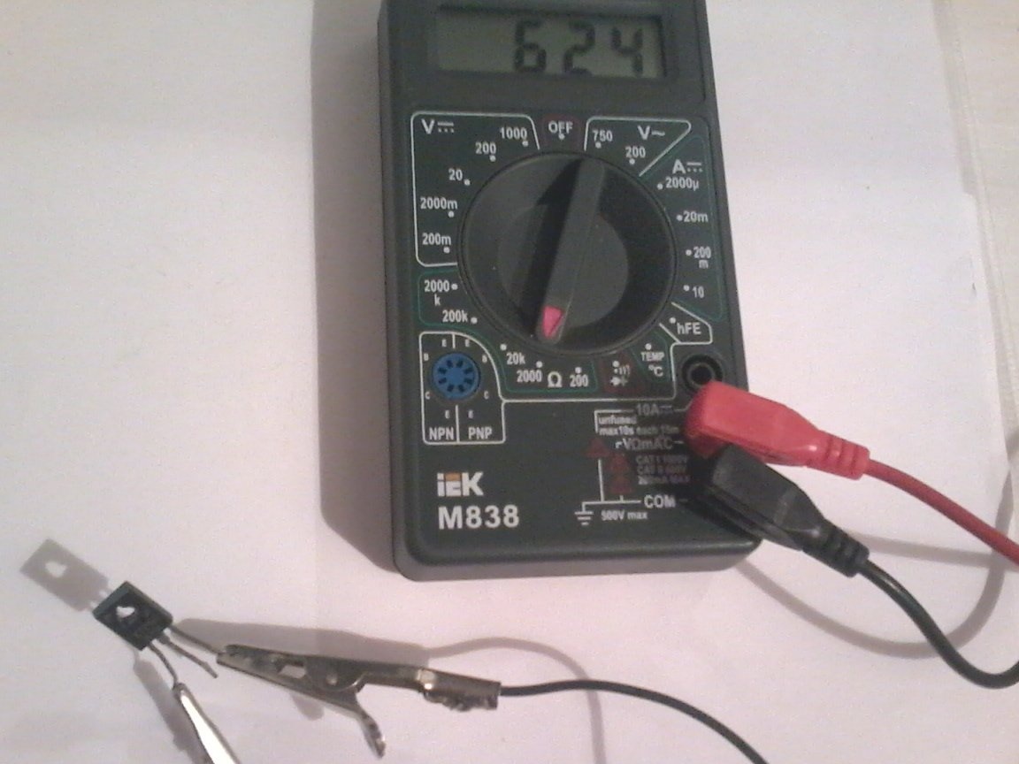
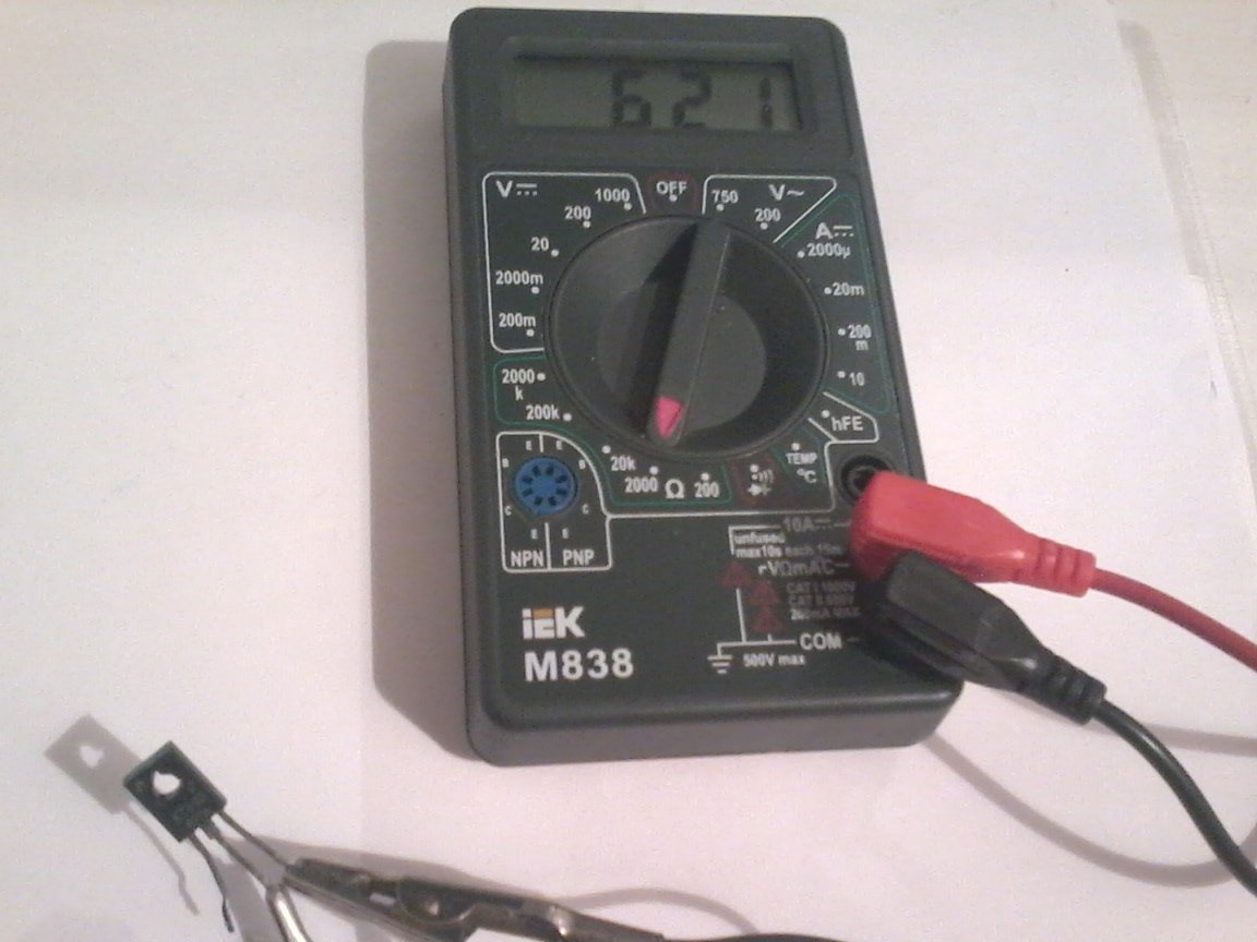
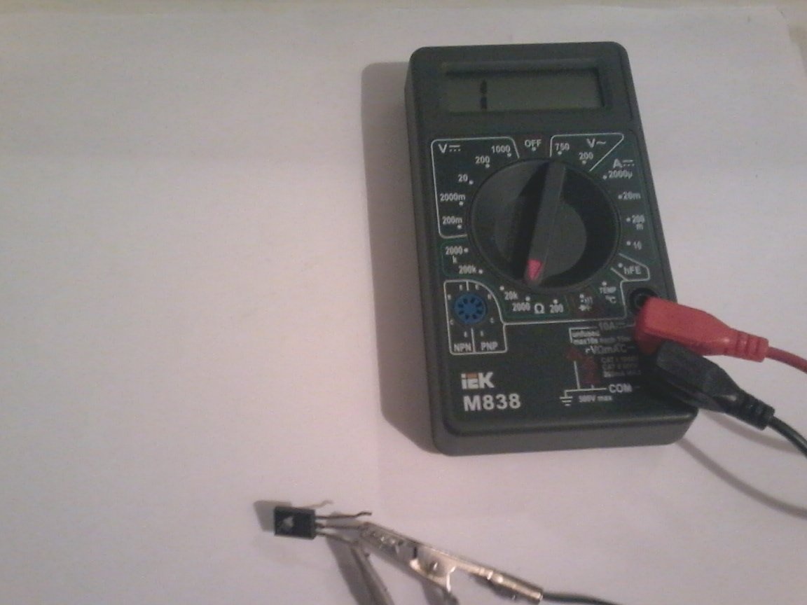
We check the transistor and all other details for their performance, so they are SECOND-HAND.
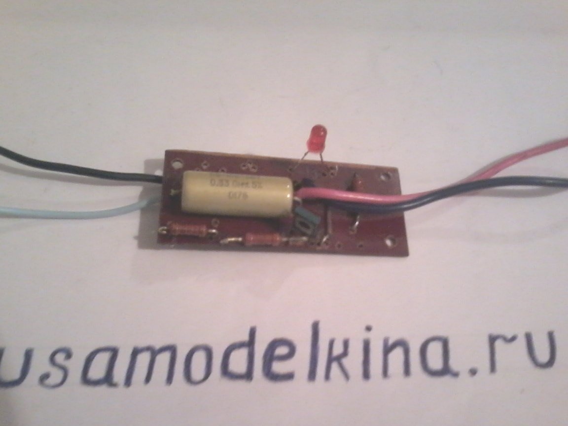
Step 2. We place the details on the printed circuit board, and we solder everything
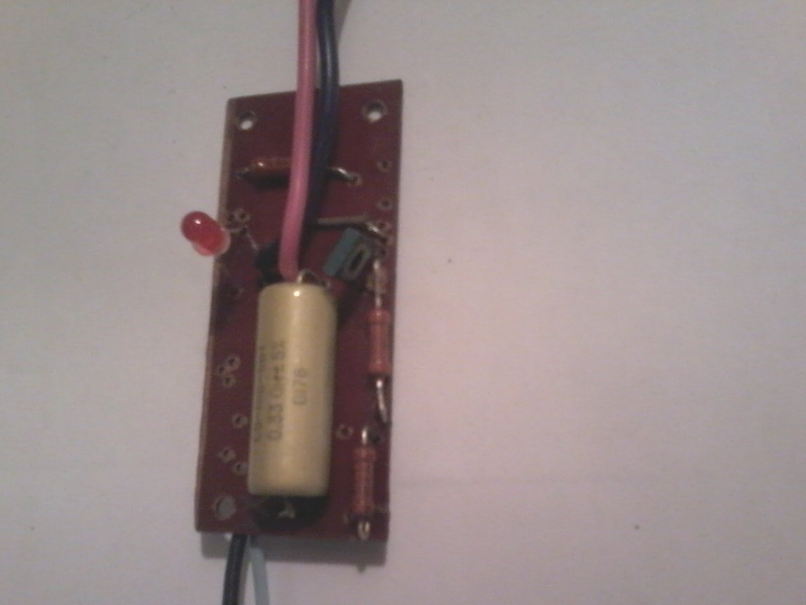
Check the correctness of the soldered circuit.
Step 3
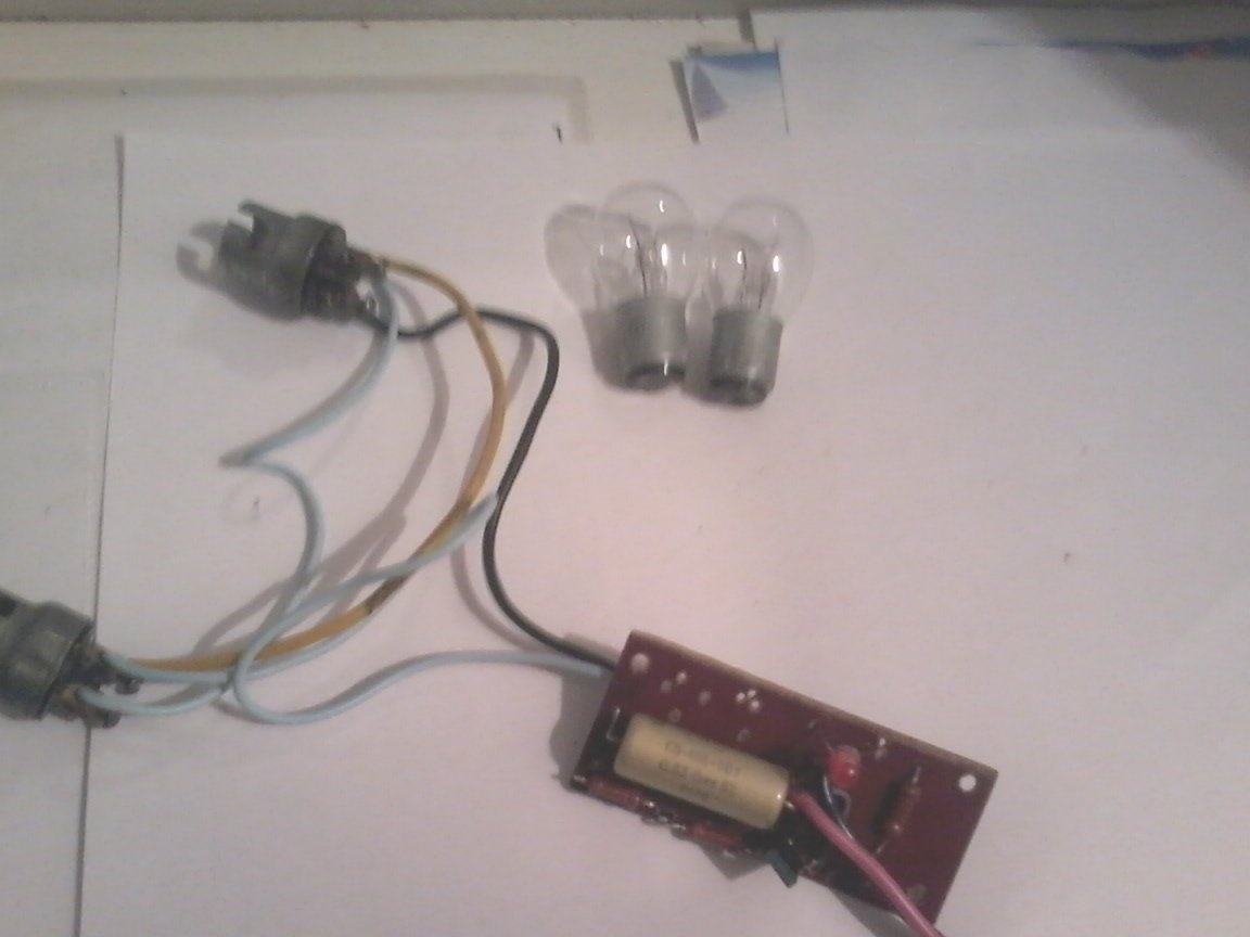
We are setting up a scheme. To do this, connect the stop lamps to connector X1, everything is shown in the photo.We supply + 12 V power to the X2 connector, and minus 12 V power the LED cathode and the second contacts of the stop lamps. When both lamps are on, the LED is also on. When you turn off one of the paws, the LED should go out. If it continues to burn, then we select the resistor R1, and make sure that the LED goes out. When two lamps are turned off at once, the LED also does not light
All adjustment of the scheme is completed. With a minimum of details, good control over the brake lamps is ensured. That's all.
I wish you all great success in the construction of homemade products.