


Not in every car There is a voltmeter or an on-board computer, and unfortunately only a light bulb showing battery charging. To monitor the status of the battery, I bring to your attention homemade, which will control the voltage in the on-board network of your car. Here is her outline.
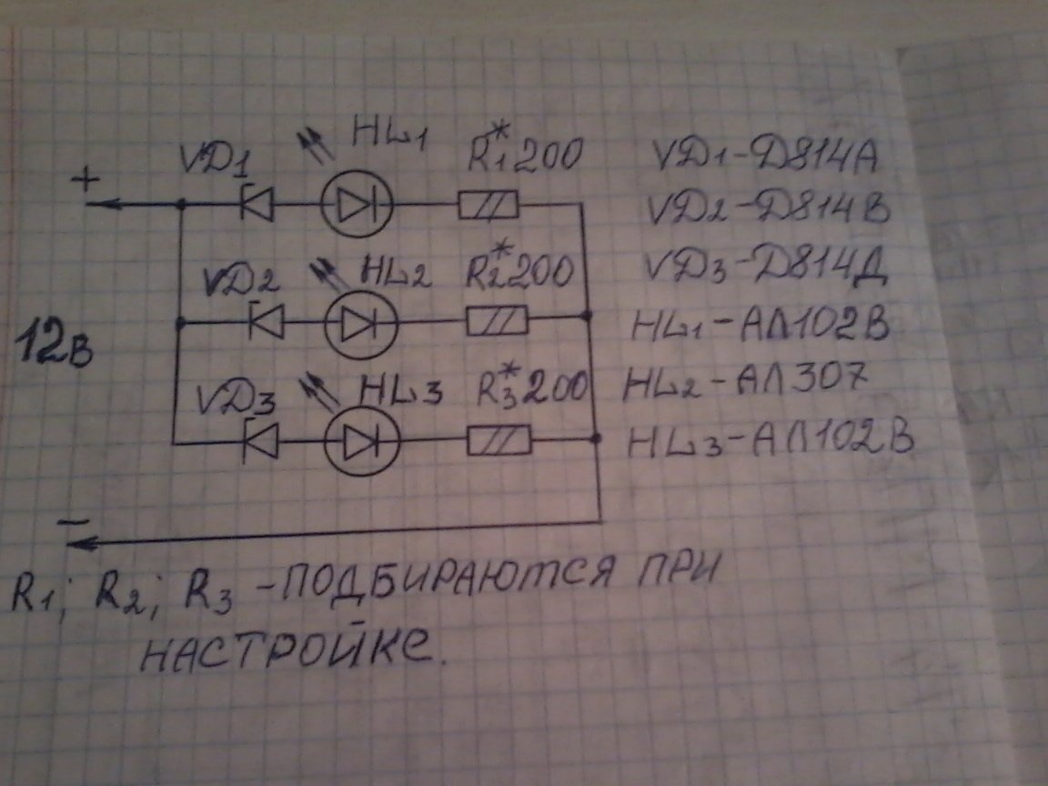
And now a little about the work of this indicator. When the battery voltage drops below 10.8v, the red LED HL1 lights up.
At a voltage of 11.8 -13.8V, the green LED HL1 and HL2 is on. When the voltage is increased to 15V or more, the red LED HL1, HL2 and HL3 is on, then the generator voltage regulator is out of order.
To assemble the indicator, we need the following parts and tools:
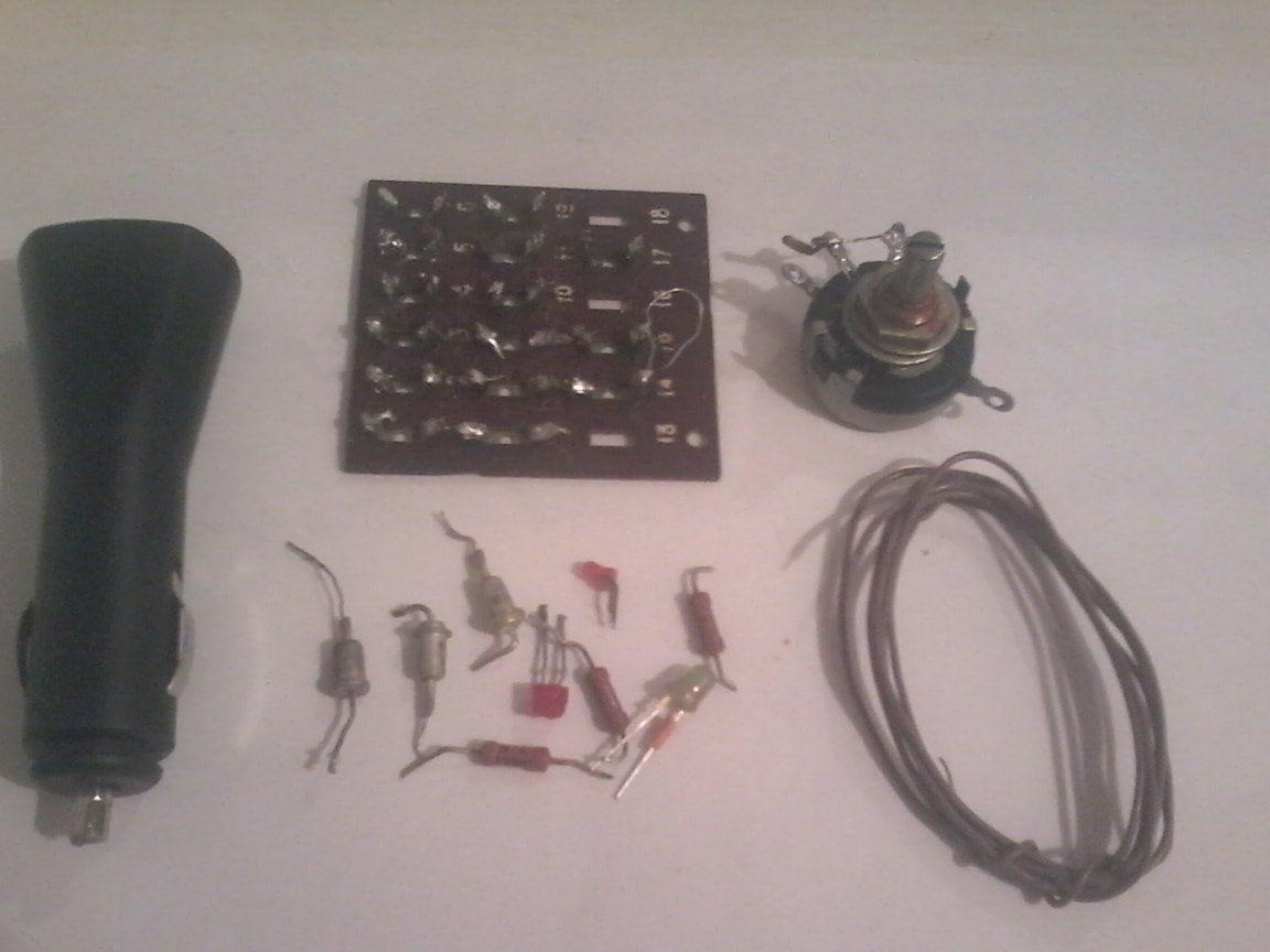
1 - Zener diodes D814A -1pcs; D814V -1pcs; D814D-1 pc;
any LEDs, for example AL 102V or AL 307, in general 2 pcs red, 1 pc green;
resistors MLT-0.25 W 200 ohms - 3 pcs; one variable resistor SP-1; 6.8 com to configure the circuit. circuit board;
burnt USB car charger for phone.
2 - soldering iron; solder; mounting wires; nippers; tweezers; screwdriver, stationery knife, drill, multimeter, power supply for tuning.
We assemble as follows.
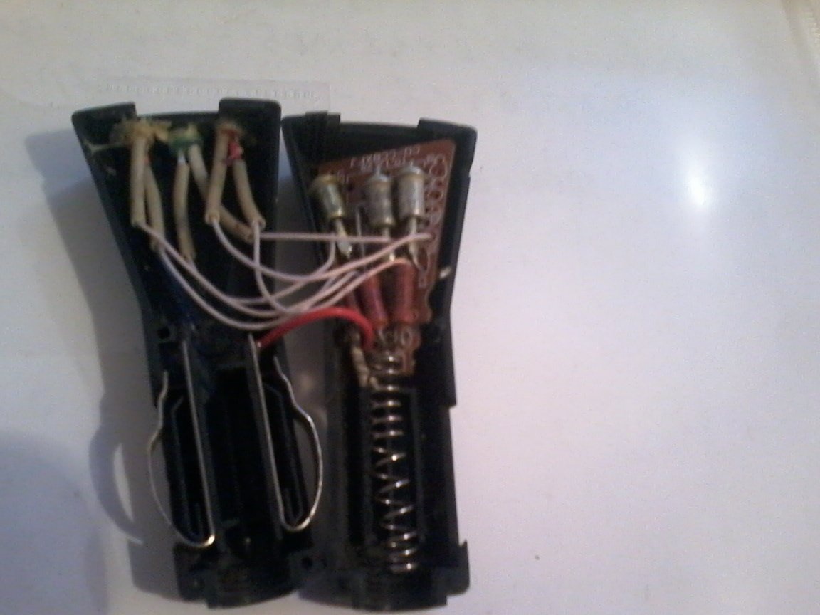
Step 1. We take the burnt car USB charge, disassemble it, We remove all the radio components from its board.
Step 2
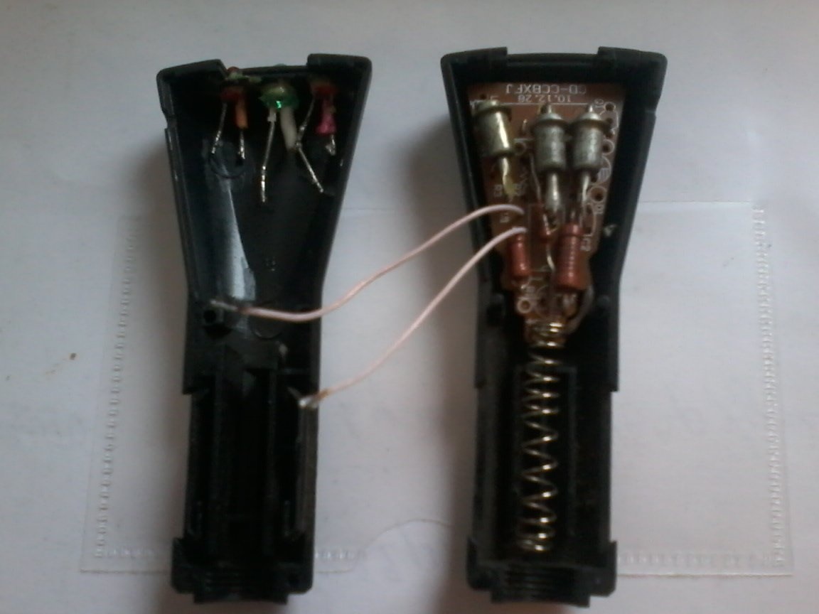
In one half of the charging case in its upper part we make 3 holes for the LEDs, and install the LEDs in them, green in the middle. On the printed circuit board, we make the corresponding holes for the zener diodes and resistors. Extra print tracks can be removed with a stationery knife.
Step 3
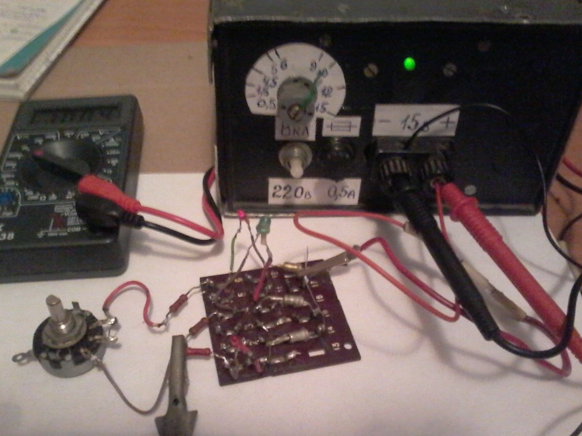
We take the circuit board, solder the entire indicator circuit on it. After that we proceed to the setup.
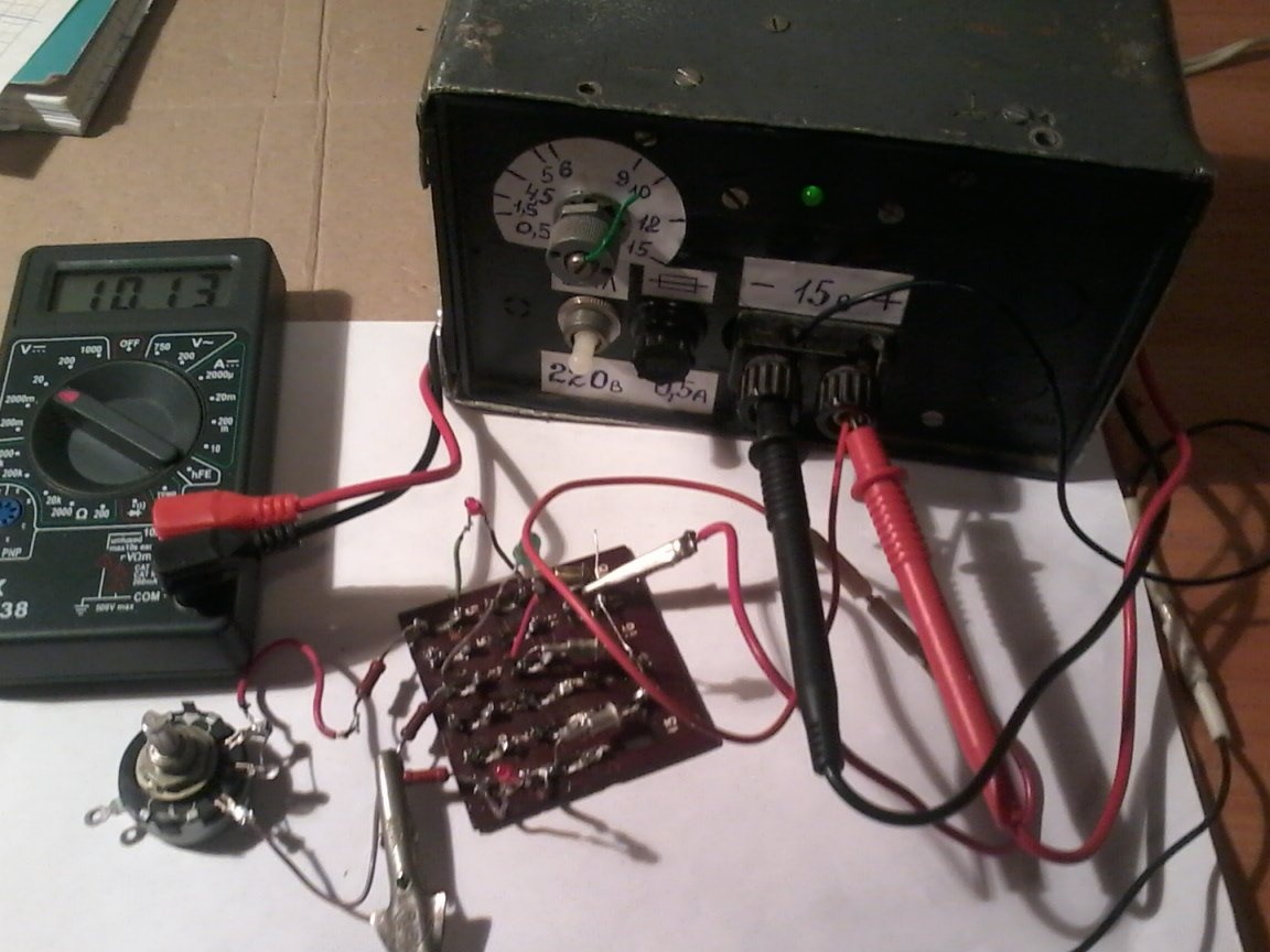
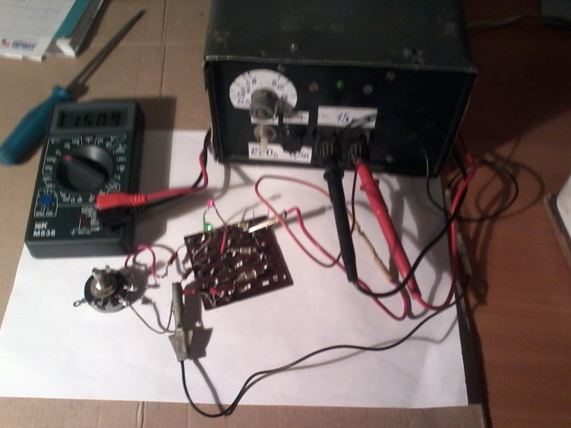
In the wire gap between the cathode of the LED HL1 and resistor R1 we put a variable resistor of 6.8 kΩ, we connect power to the input of the 10.8 V circuit, and turning the variable resistor slider, we achieve the glow of LED HL1. then turning off the power, measure the total resistance of the resistors (R1 and variable resistor). We put a constant resistor of the measured value in the circuit, removing the variable resistor from it.
Setting up the HL1 LED is completed, we also configure the remaining LEDs. To configure HL2, we supply 11.8-12 volts. To configure HL3 - 15 century. After installing the resistors we need in the circuit, we supply power to the input of the 15v circuit - all three LEDs should glow. We turn off the power to 14 in the LED HL3 should go out. If the input voltage is below 11.8 V, the HL2 LED should go out. And at a voltage below 10.8 V, the HL1 LED should also go out. If this is all as described here, then the indicator is working correctly. And if not, then you need to more accurately select all the resistors.
Step 4
We unsolder all the radio components from the assembled circuit board, and transfer them to the USB charging board. After that, connect the power, and check the operation of the indicator. We assemble the charging case, we check in assembled form by connecting the power from the unit or in the cigarette lighter socket of the car. With a minimum of parts - quite good control over the state of the car battery. I don’t know about you, but the work of this indicator suits me perfectly.