In conditions of heavy traffic, the driver is practically deprived of the opportunity to pay attention to the light indicators signaling the maximum modes of the car, which are located on the dashboard. These include lowering the oil pressure in the engine lubrication system, increasing the temperature of the fluid in the cooling system, lowering the brake fluid level, prolonged state of the parking brake, lowering the fuel level below the reserve, and not turning the turn signal on time.
The appearance of any of these limiting modes should attract the driver’s attention in order to avoid a traffic accident or, at best, failure of one of the vehicle’s systems. An acquaintance of mine “rattled” the engine, and all because of the fact that on a sunny day he did not see the “low oil pressure” on the instrument panel and the lamp went on, and continued to move as if nothing had happened. The result of this is an expensive engine repair.
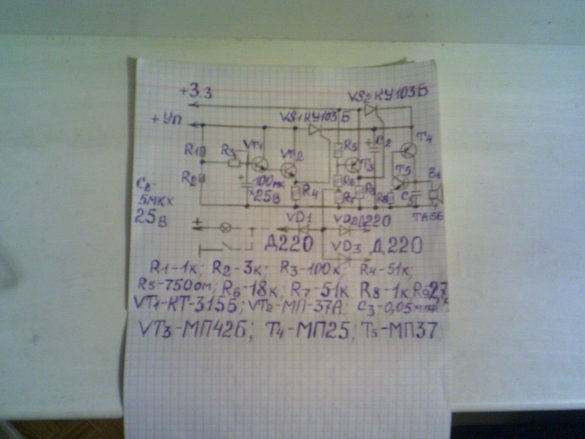
Duplication of the light indication with a sound signal increases the safety of car operation. I took the circuit of the signaling device from the collection "To help the amateur radio" issue 102, slightly changed the circuit. Instead of the sound generator shown in the diagram, I assembled my own. It was previously published in the previous homemade. The sound quality of my generator is much nicer than that of the generator that was in the circuit. Here is the signaling device diagram.
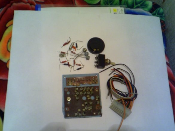
To assemble it, we need the following parts and tools:
1 - resistors MLT-0.25, 1kom, 3kom, SP-1 100kom, 51kom, 750 ohm, 18kom, 2.7kom, 1kom, electrolytic capacitors 100uf at 25v, 5uf at 25v, MBM -0.05 microfarads, D-220 diodes, -3 pcs, KT315b transistors - 2pcs, MP37a, -2pcs, MP42b, MP25, MP26b, KU103b-2 thyristors, TA-56 earphone, one double toggle switch, or two single, Installation wires solder. 2 - soldering iron, tweezers, pliers, wire cutters, circuit board with petals. We assemble as follows:
Step 1
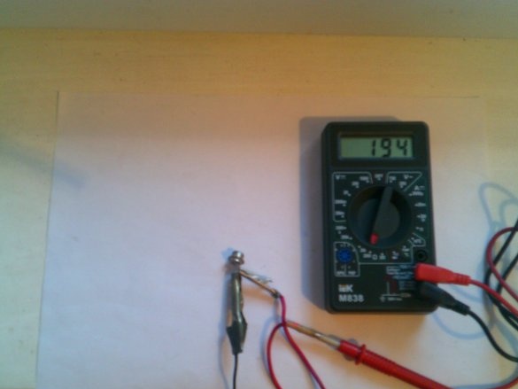
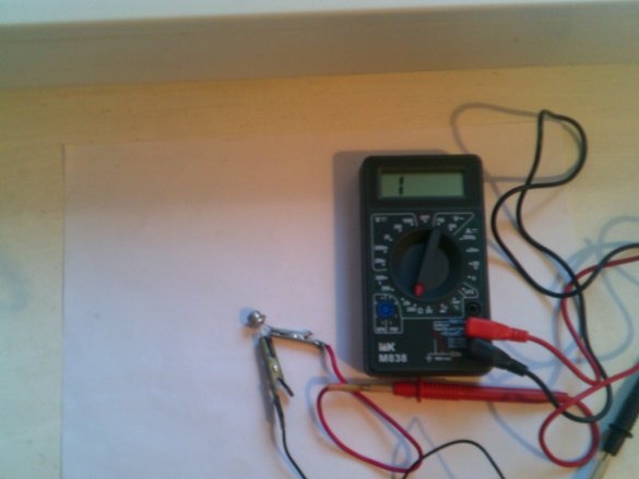
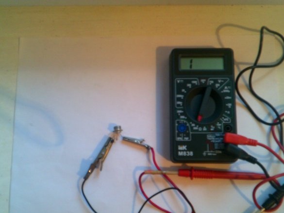
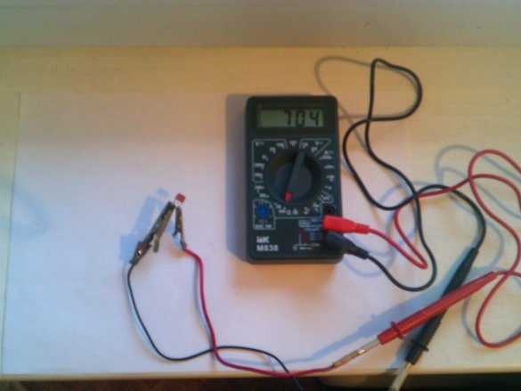
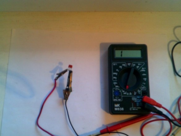
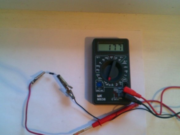
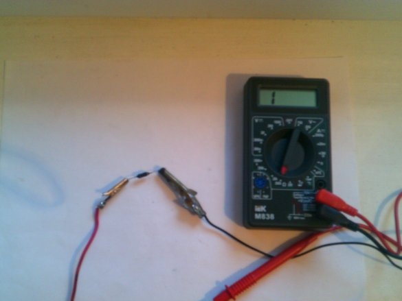
We check the serviceability of all parts.
All this is shown in the photo.
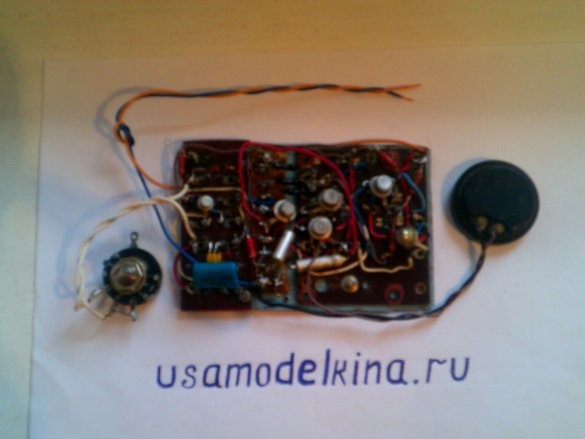
Step -2. Then we solder on the circuit board first all the necessary jumpers, then resistors, capacitors, diodes, and then we solder transistors and thyristors.
Step -3. Set up as follows: The buzzer is combined with a time relay. When the turn indicator is turned on, the indicator does not respond with a sound signal.If, for some reason, after some time after turning on, the direction indicator does not turn off, an audible signal will turn on, drawing the driver's attention to the need to turn it off manually. Other limit modes are not encountered during the normal operation of the vehicle and the delay in switching on the sound signal is not dictated by necessity.
The delay time between the moment the turn indicator turns on and the moment the sound signal appears can be adjusted with a variable resistor R3, depending on the driver’s habit of turning on the turn indicator more or less before the maneuver.
The diagram shows only three diodes that are connected to the indicator lamps of the controlled modes of the car. Their number may be increased. It is necessary to select the transistor mode of the key stage VT3. To do this, when one of the diodes is closed to the cathode, the resistance of the resistor R6 is selected so that the thyristor VS2 reliably unlocks at a voltage at the “+ ЗЗ” terminal equal to 10.8 V, which corresponds to the minimum voltage of the onboard network. Then, when the diode cathode is disconnected from the mass, the resistance of resistor R7 is selected so that the thyristor is reliably locked when the voltage at the “+ ЗЗ” terminal is 14.5 V, which corresponds to the maximum supply voltage. When selecting these resistors, it is best to connect variable resistors of the same ratings in series with them.
After selection, measure the total resistance and put a constant resistor of the desired rating. In the absence of the transistors indicated on the circuit, they can be replaced by any low-power silicon and germanium transistors of the corresponding type of conductivity. The gain h21e of transistors VT1 and VT2 must be at least 60. Establishment is completed. And one more tip, according to the scheme, the power supply wire of the signaling device should be connected to the “+ ЗЗ” terminal, that is, to the ignition switch. Each time the ignition is turned on, the indicator lamps of the modes we need will light up, therefore, an audible signal will turn on each time, and until the engine starts, it will turn off. To prevent this from happening, it is necessary to connect this wire instead of the ignition switch to the “D” terminal of the machine generator, since + 12V voltage appears on this terminal only after the engine is started.
Next, we put the assembled board in a case of a suitable size, install a switch, put out the necessary wires, and install it in a machine in any convenient place.
I don’t know how you need this signaling device or not, but for me it is very necessary. Friends decide "the inhabitants of our site."


