

Hello, friends the inhabitants of our site! For those who are often faced with the repair of household and other equipment, I suggest assembling a small device. They can check the bipolar transistors of low, medium and high power of both structures without disconnecting the transistor leads from the installation.
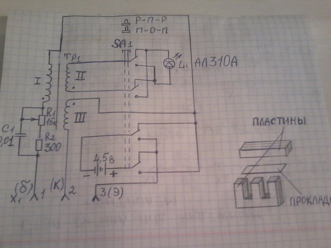
The device diagram was taken from Radio magazine No. 3 of 1984, and No. 3 of 1985 already with the finalization of the scheme. Here is a modified device diagram
To assemble the device, we need the following materials and tools.
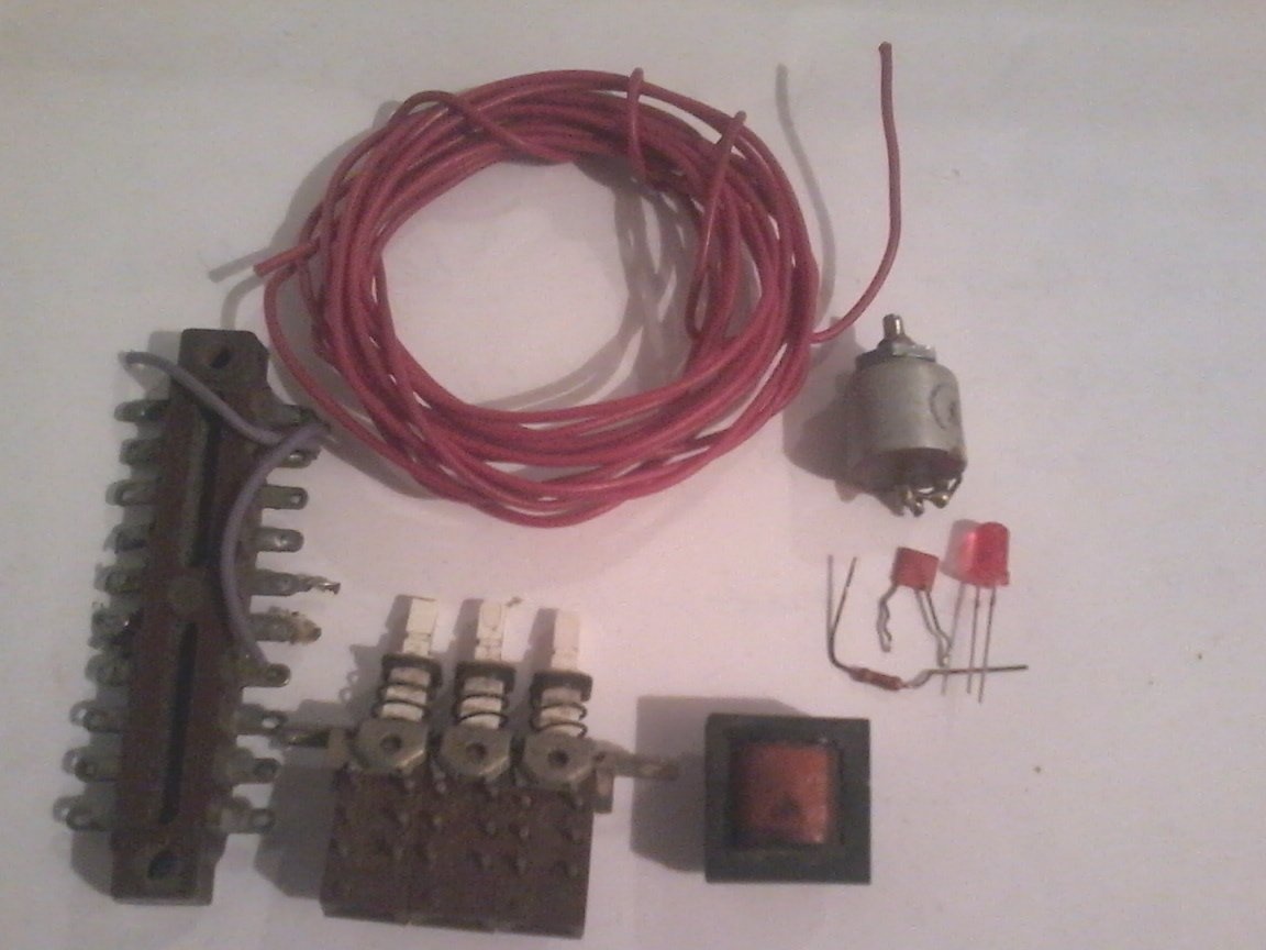
1 - the output transformer of the radio climber "Mountaineer" or any other with a magnetic circuit Ш 6 x 8 mm; push button switch with four contact groups; AL 310A LED, others with a consumption current of up to 20 mA are suitable, a variable resistor of the type SP -0.5, or SP-1 at 15 kΩ, an MLT resistor -0.125 W per 300 ohms; 0.01 uF capacitor.
2 - soldering iron; solder; tweezers; mounting wires; 10 -15 cm of copper wire with a diameter of 1 mm; connector SG-5 or SG-3; nippers; pliers; 4 meters of sew wire -1 0.2 mm, 1 meter of wire sew -1 0.3 mm - for winding the transformer.
{banner_tovary}
We assemble as follows.
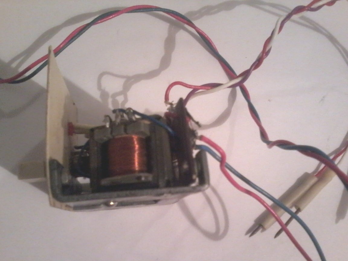
Step 1. We wind the transformer. To do this, we disassemble the existing transformer, remove all windings from it, and wind new ones. Collector winding III contains 100 turns of PEV-1 wire 0.2 mm, base (I) - 20 turns of PEV-1 wire 0.2 mm, signal (II) - 30 turns of PEV-1 wire 0.3 mm. We isolate the windings from each other with electrical tape. Dots in the diagram indicate the beginning of the transformer windings. When assembling the plates, a thin paper gasket is installed between the plates. All this is shown in the diagram.
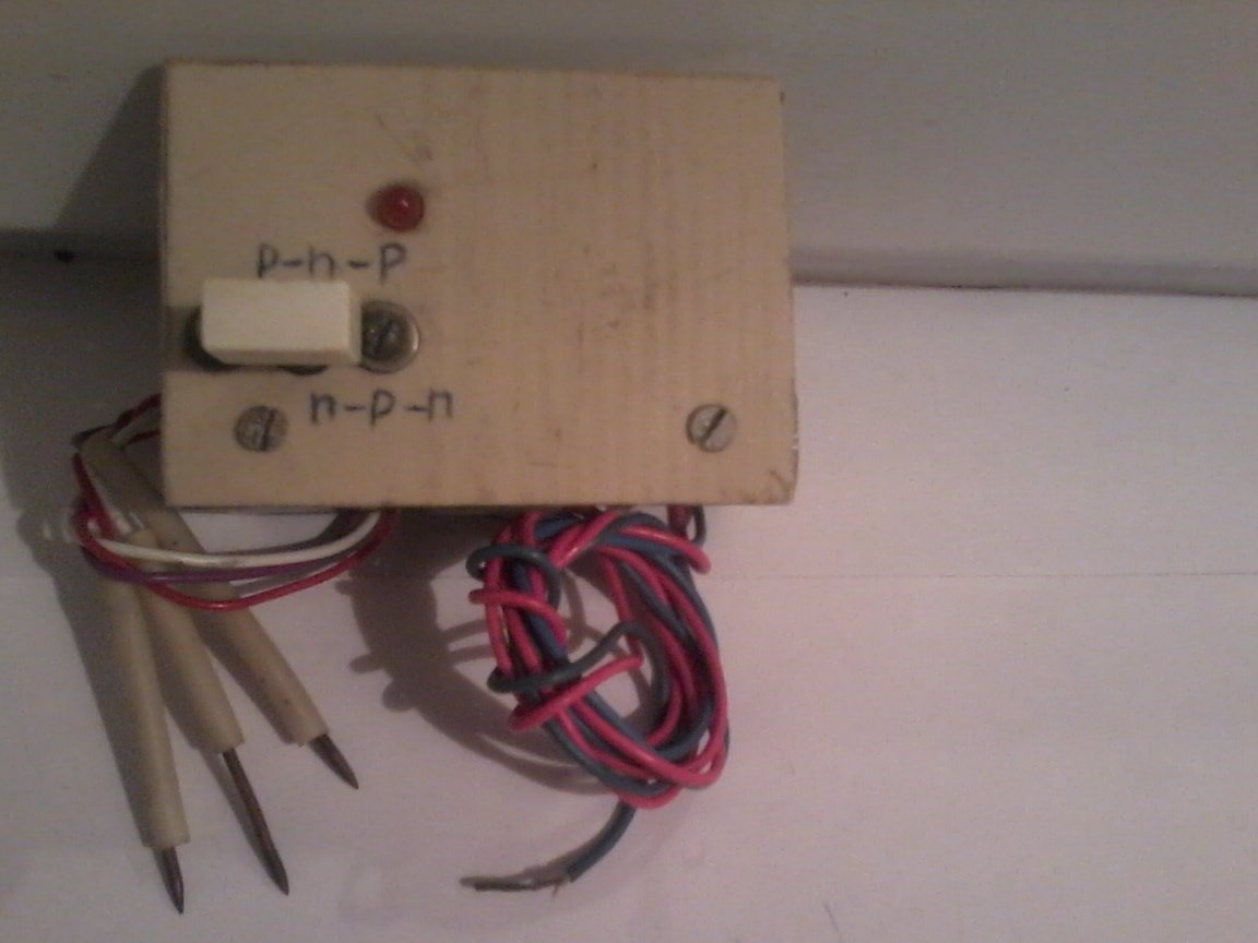
Step 2 We place all the details on the getinaksovoy plate or on the finished corner, as I did.
Step 3
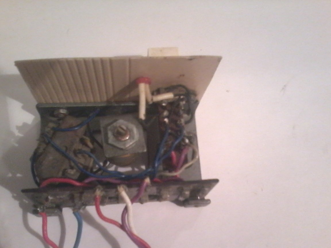
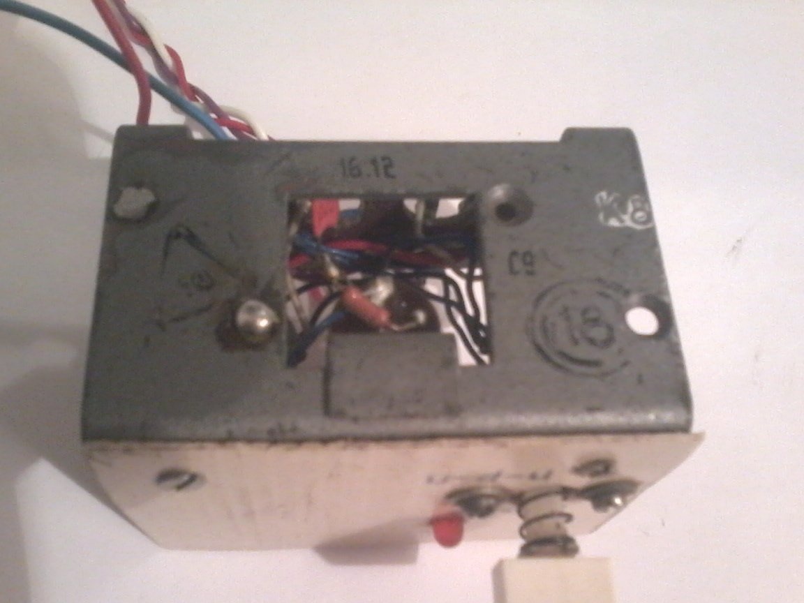
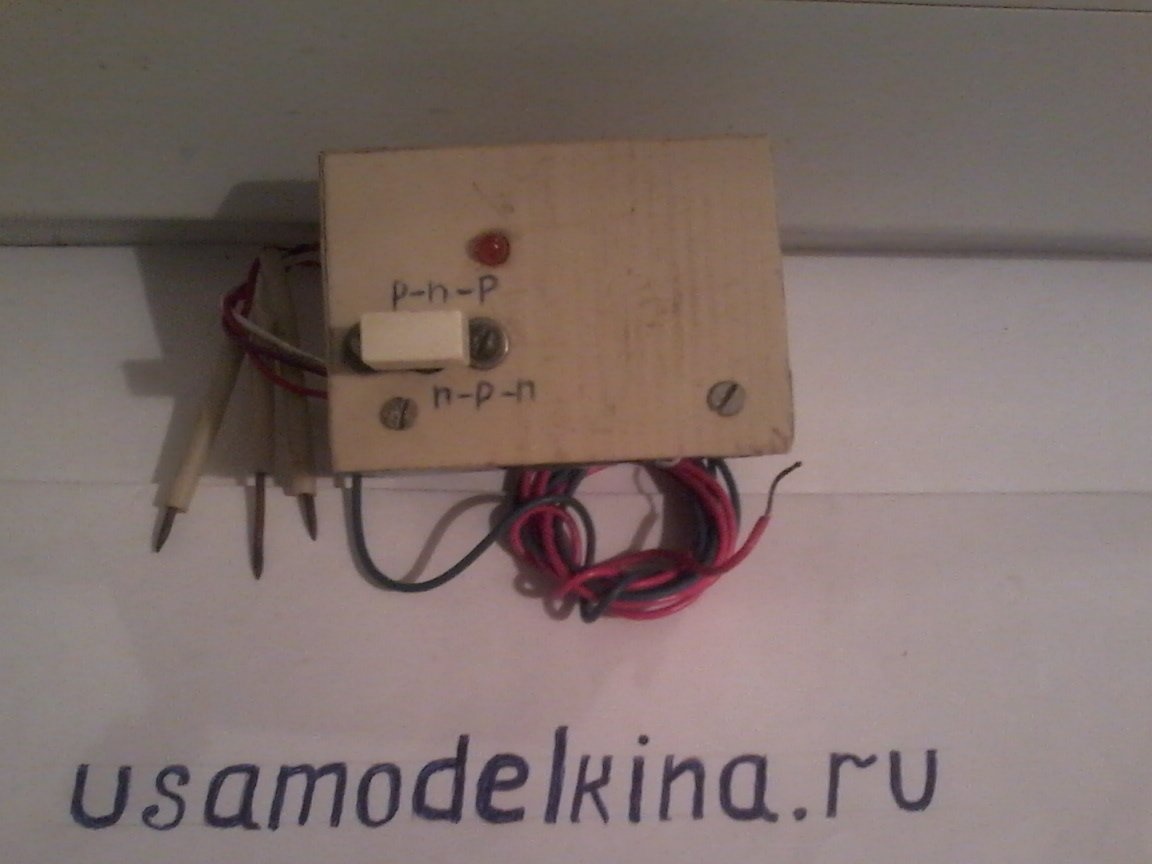
We solder the whole circuit, check the correct assembly. I made 3 probes from a copper wire with a diameter of 1 mm, sharpened their ends with a file. I soldered wires to the probes, and connected the “white” to the device to terminal 1 “base”; red - to terminal 2 “collector”, purple to terminal 3 - “emitter”. I supply power to the device from the power supply in blue - minus, and in red - Plus 4.5 V. Switch SA 1 select the structure of the transistor "P-N – P" or N – P-N "
Step 4 Set up the device as follows
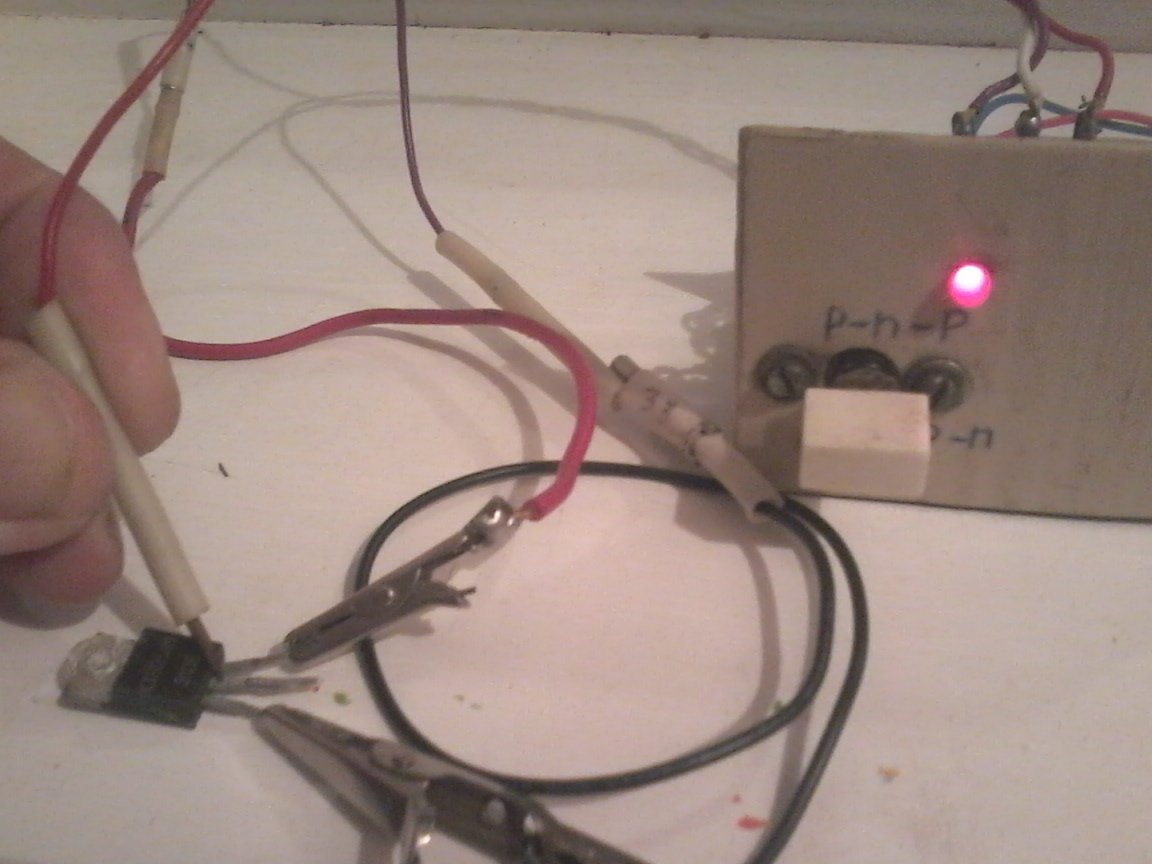
We connect to the terminals 1, 2 and 3, respectively - the base, collector, and emitter of the tested transistor. We supply 4.5 V power to the device. With the switch SA 1, we set the desired structure of the transistor under test, rotating the variable resistor slider, we achieve the LED glow.If the transistor is operational, then the LED should light up, and if it is faulty, then the LED does not light.
If the device does not work, then check that the transformer windings are connected correctly, the end of the first winding should be connected to the beginning of the third transformer winding. When checking transistors in a block of faulty equipment, it is not necessary to solder them from the installation, however, if the terminals are heavily bridged, for example, by large capacitors, you will have to disconnect at least the base terminal from the device circuits. I don’t know whether you believe my friends or not, but this device has been working with me for more than 20 years. He tested several hundred transistors at my former job. And at home, he also helps with the repair of faulty equipment.
Such a device is useful to any radio master. I wish you all success in designing your homemade products.