
The laser center finder is an extremely useful addition for a milling or drilling machine and can be used for various alignment tasks with an amazing degree of accuracy. Centering a milling cutter or drilling machine over a hole or other element on the workpiece is very easy.
There were three functions that the master wanted to enable, namely;
1. The ability to continue processing in the place in which it was installed.
2. Adjustable laser angle.
3. Adjustable focus.
This tool was made entirely from an old damaged laser level and several pieces of aluminum from a waste box. The only “purchased” items were two AAA batteries.
Step 1: Preparing Materials and Tools
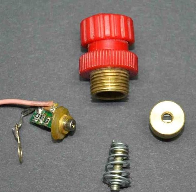
The master cut the end of the old level to remove the laser unit. The laser and its lens were mounted inside a small aluminum case. He turned this case to remove the mounting flange that is visible in the photographs. He needed to recycle and use this case because it was internally threaded for a brass lens holder. This thread allows you to adjust the focus. The last photo also shows the red cover and switch for the battery compartment and the spring contact of the battery.
The frame was made of several aluminum waste parts. The dimensions of the parts depend on the size of the device on which they will be installed, and remain at the discretion of the reader.
Instruments:
- The master used a milling machine to shape the frame;
- The lathe will be useful for the manufacture of adapter drill chuck;
- Soldering iron for connection;
Step 2: Frame Making
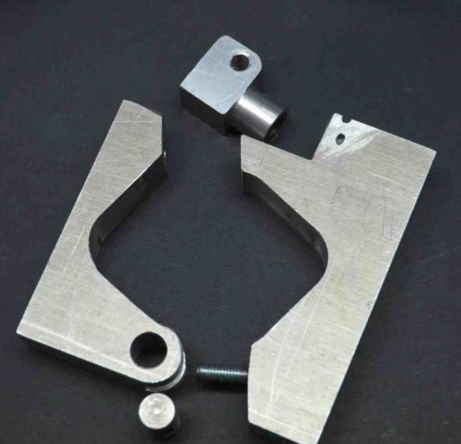
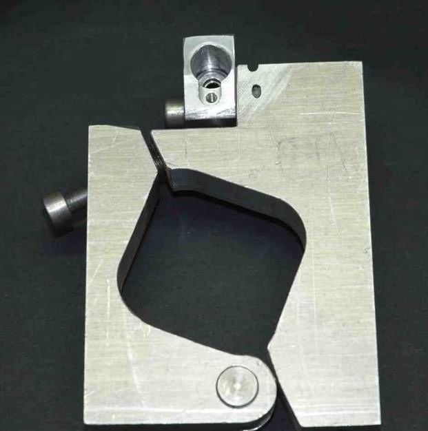
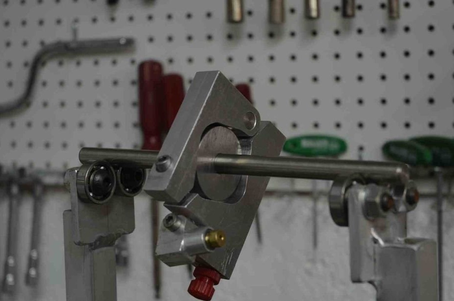
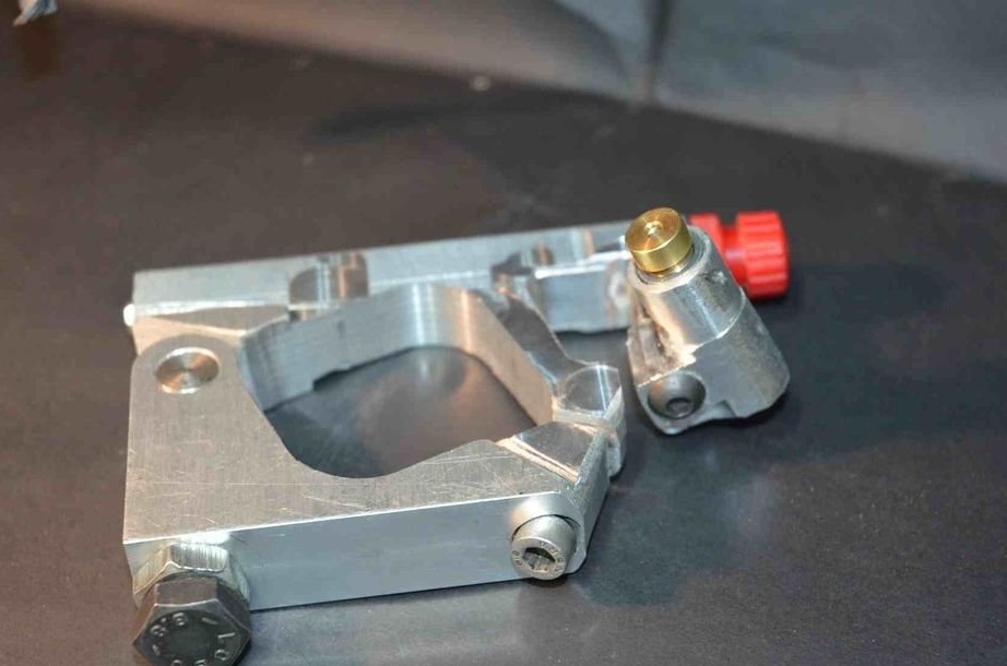
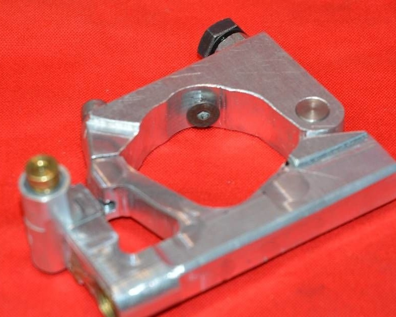
The frame consists of three main parts. Two of them form a clamp for attaching to a milling or drilling spindle, and one of them is drilled for the battery compartment. The third part is the laser unit housing, which is bolted to the half clip of the battery compartment so that it can be rotated to align the laser with the desired circle diameter.
Two halves of the clamp are interconnected by a hinge and a bolt. See the first photo above. This design is fast and reliable.The hinge consists of a trunnion made of a piece of 12 mm steel rod, the length of which is equal to the thickness of the clamping material (in this case it was 19 mm). This pin was drilled in the center and a 6 mm thread was cut. The other clamp had a piece of 6 mm thread that screwed into the pin. The hinge clamp is held closed by a single bolt on the spindle.
Step 3: Laser Design
The original laser housing is glued to the drilled hole in the new adjustable support. The original threaded housing approached the brass lens assembly, which made it possible to change focus according to the distance between the laser and the workpiece. Between the lens assembly and the laser is a spring that acts as a focus adjustment lock.
The back of the laser unit was filled with epoxy after small wiring was soldered to the laser circuit board. These wiring goes to the battery compartment.
Step 4: Battery Installation
The original spirit level had a red screw-on battery cover that turned on the switch. The master wanted to keep this detail, but it was screwed on, and the author did not have a suitable threaded tap. Therefore, he cut out the original brass part into which it was screwed and pasted it into the hole in the battery compartment. Being copper, it was easy to solder a wire to transfer energy to a laser. A spring contact was installed at the other end of the battery hole, which is shown in step 1.
Step 5: Balancing
The master has device for wheel balancing motorcycleswhich he made many years ago, which he uses for various balancing tasks. He made a spindle with a thick disk for mounting a laser finder, and this made it possible to check the balance, as shown in the figure.
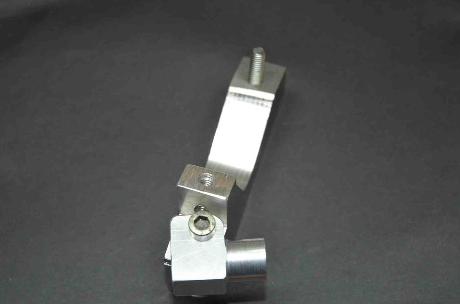
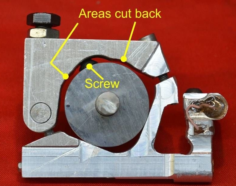
The master wanted to be able to use the laser device when milling, so it should be well balanced enough to avoid vibration. First, the balance was checked, which revealed the concentration of too much mass at the laser end. Excess metal was grinded in this area, and an adjustable steel bolt and 10 mm nut were added to the opposite side. as a counterweight. Shown in the second photo above. This brought the balance to an acceptable level.
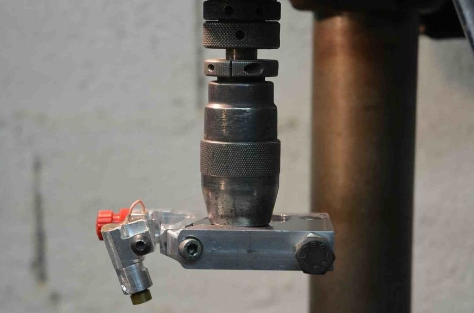
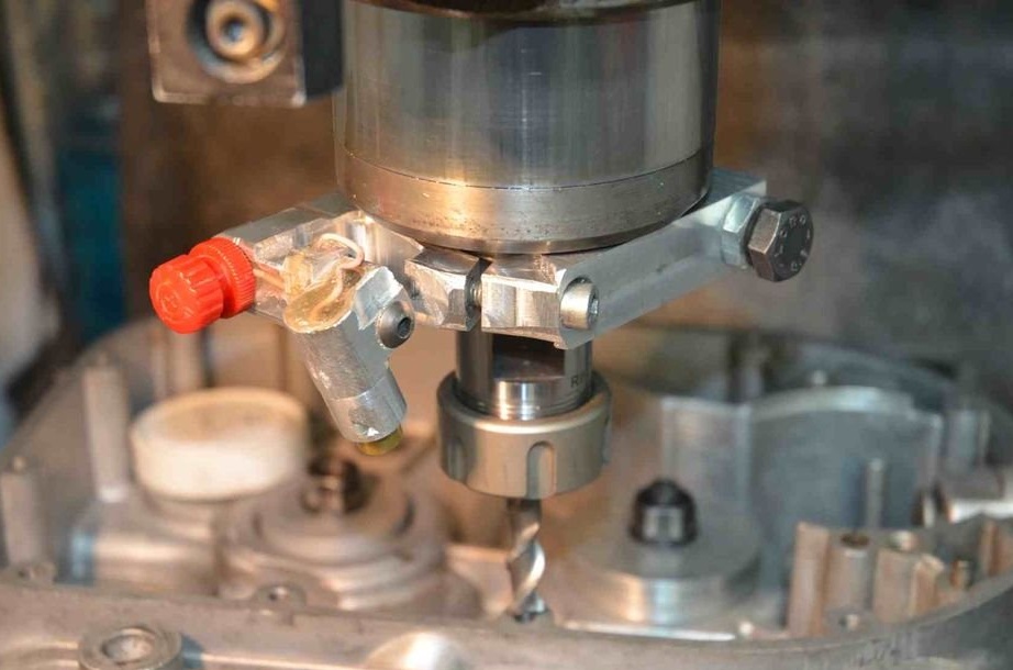
Step 6: Installation on the router
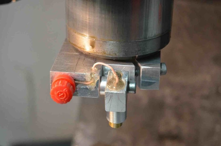
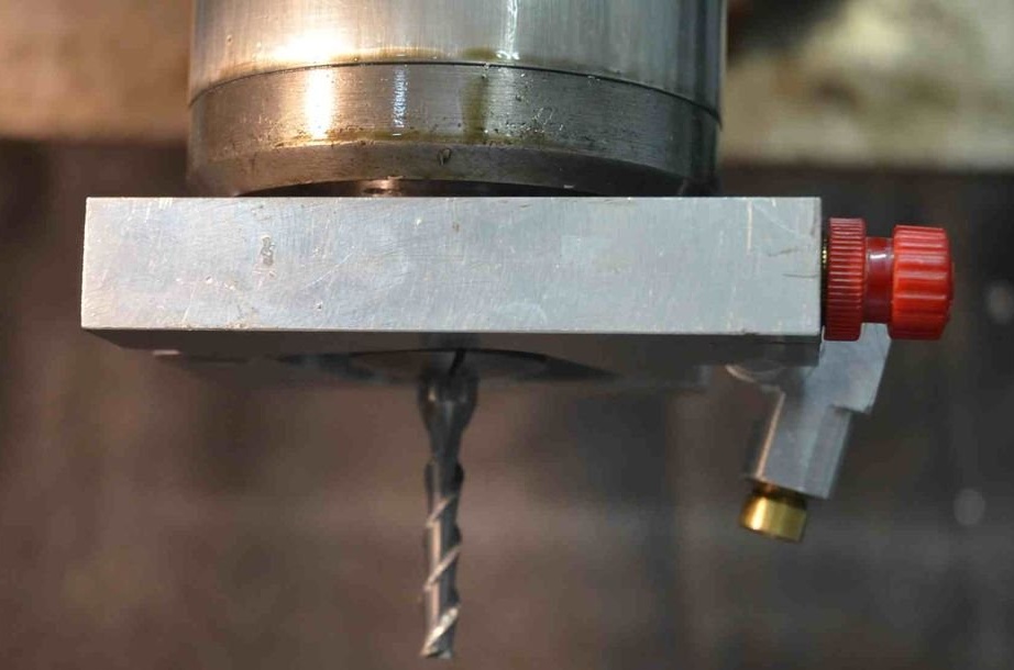

The assembly is attached to the spindle of the milling machine so that it can rotate with it without complicating the use of the cutter.
Since the laser is offset relative to the axis of the cutter spindle, the light emitted by it will describe the circle on the workpiece below. The diameter of this circle is determined by the distance between the spindle and the workpiece, as well as the angle of the laser beam, which the master made adjustable. Focus can be adjusted as described in the previous step to get a visually clear, accurate circle.
Step 7: Installation on a Drilling Machine
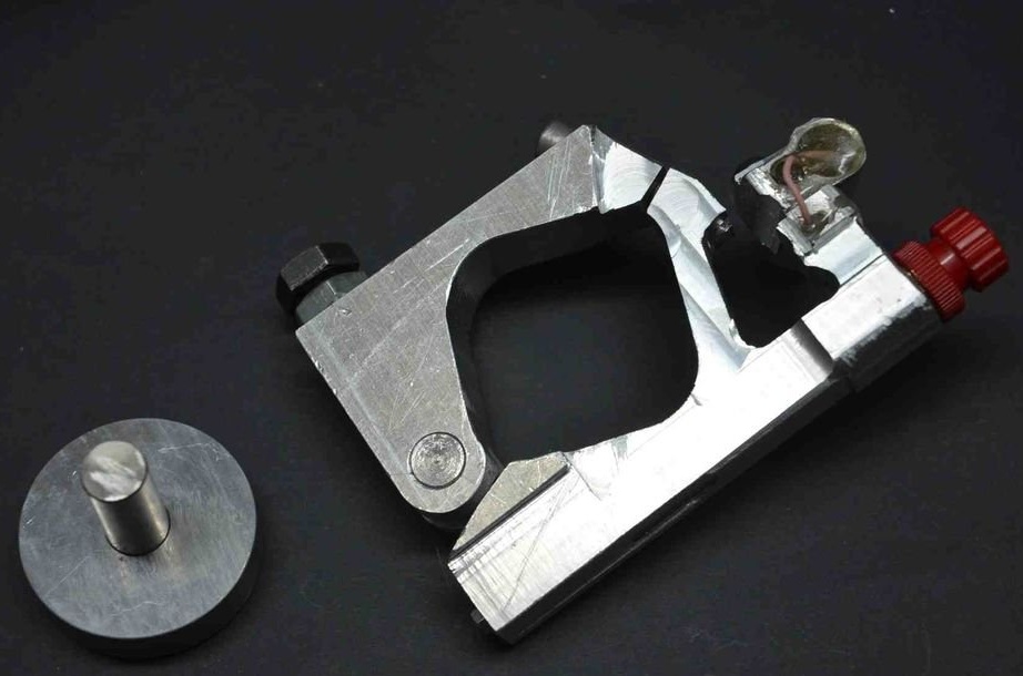
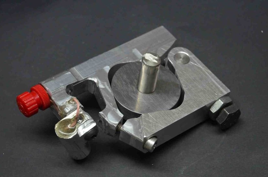
The usefulness of this device is enhanced if it can be mounted on a drill chuck, either on a milling cutter or in a drill stand. To use this function, the master made a special disk for gripping the clamp with a central shaft of 12 mm to install the cartridge. The photographs show the installed unit, as well as the mounting disk.
Step 8: Problems
When the master first began testing a laser device on his milling machine, he noticed a strange phenomenon.
Initial freehand tests gave excellent results, however, as soon as they were scrolled mechanically, when reaching high speeds, part of the circle disappeared. Strange huh? It turns out at such a high speed, the batteries moved away from one of the contacts. The correction was simple, the wizard simply used a stronger spring in the battery compartment.
Step 9: Modification
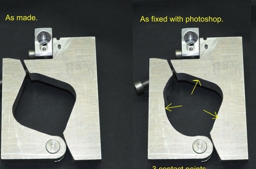
Initially, the master made a stupid mistake with the first design of the clamp.
He made four points of contact with the milling spindle. Of the four points of contact, one will not touch or will not touch as much as the other three. In practice, this did not create any problems; the clamp was always reliable.
This first photo shows how the master corrected this situation in Photoshop.
He then locked it physically, cutting off the area of the original two contact points, and then installed a flat head screw to ensure a single contact on this half of the clamp, giving a total of three clamp points.
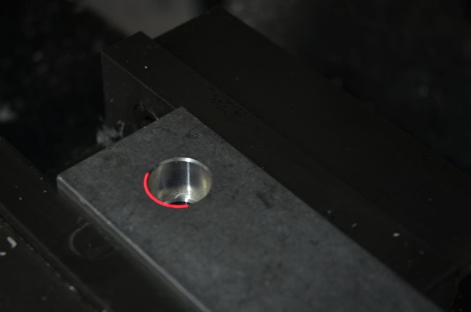
Step 10: Use
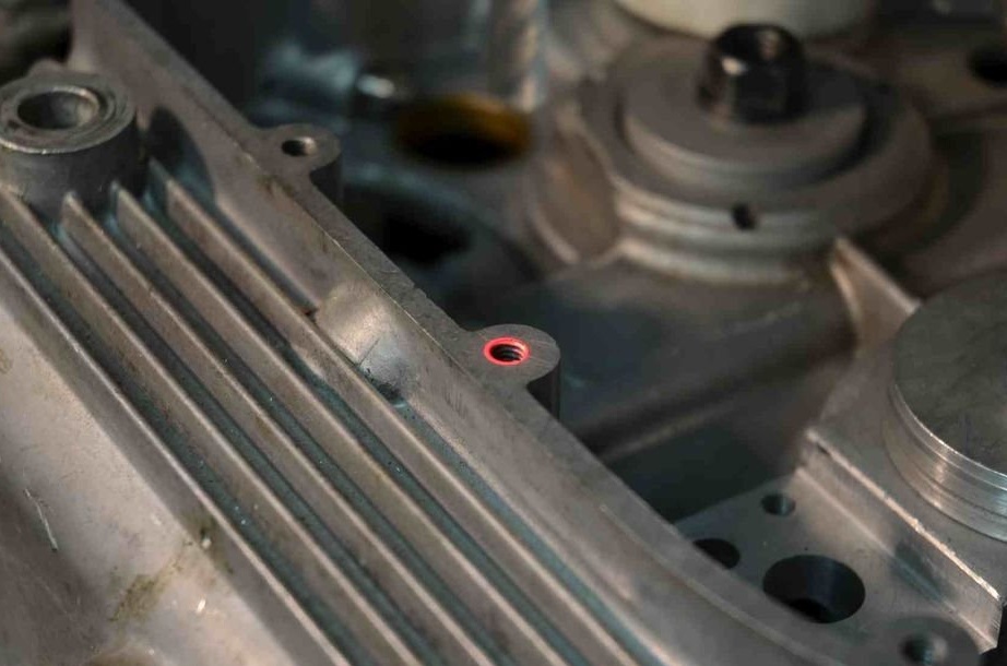

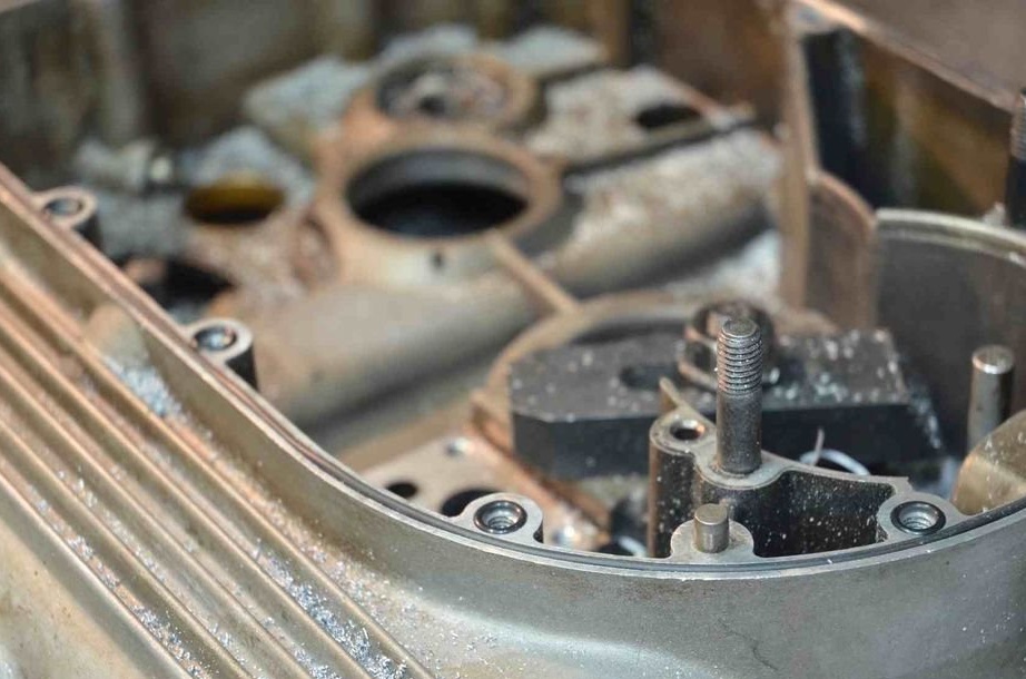
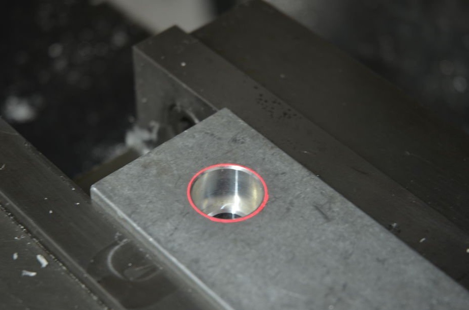
These photos show work for which the laser center finder saved a lot of time.
The craftsman needed to drill holes for the screws that secure the cover to the crankcase of the motorcycle to allow the installation of small oil o-rings.
The first photo shows how you can focus on each hole. After centering, it was only necessary to lower the cutter to a given cutting depth and go to the next hole. The whole operation was completed very quickly.
Details of creating a laser center finder can be seen in the video: