» Electronics » Arduino »Radio control equipment on Arduino

Radio Control Equipment on Arduino


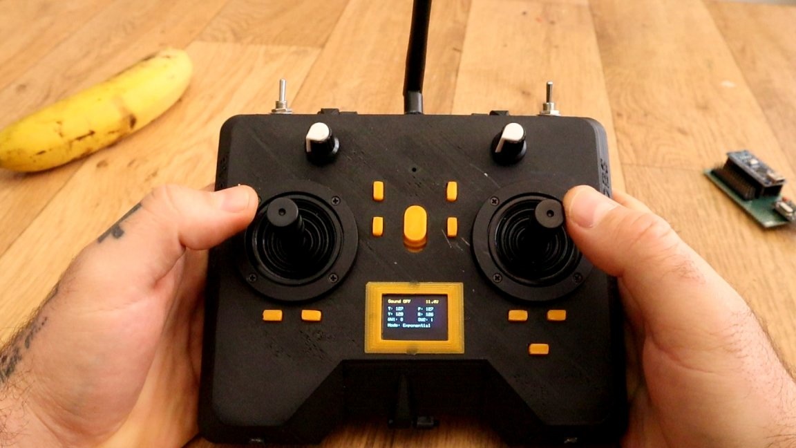
This article discusses the manufacture of proportional board-based radio control equipment Arduino. An interesting feature of the project is that the equipment was conceived as an alternative to the "adult" equipment, but which you can make yourself. There are trim keys on the transmitter, which is important for control, for example models aircraft, the transmitter is also equipped with a small display with organic LEDs, which displays basic information on the operation of the transmitter. The equipment is designed for 6 channels, 4 proportional and 2 discrete. The author also laid the foundation for the future addition of two more proportional channels, 2 potentiometers were added to the case, but at the moment they are not involved. Nevertheless, this is enough to control the model of an airplane, ship or car, and discrete channels will allow you to control the additional load, for example, the inclusion of headlights, deck lights, navigation lights or even the launch of small missiles. The equipment has two control modes - linear and exponential.


For the transmitter you will need:

1 x Arduino NANO / UNO / ProMini
1 x BMS protection board for three Li-ion cans
1 x 5.5 x 2.1 mm connector
1 x Step Up DC / DC Converter XL6009
1 x LM2596 small step-down converter (I will talk about it separately)
3 x 18650:
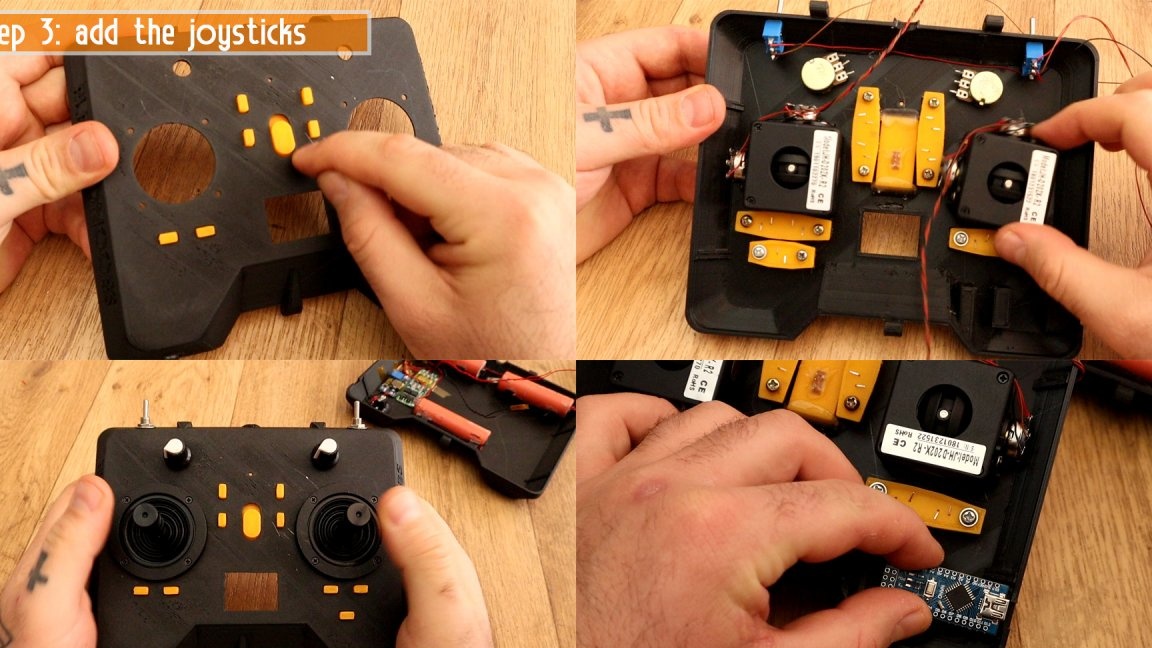
2 x joysticks JH-D202X (sold on Ali)
2 x toggle switch
1 x i2c OLED Screen 0.96 inch 128X64
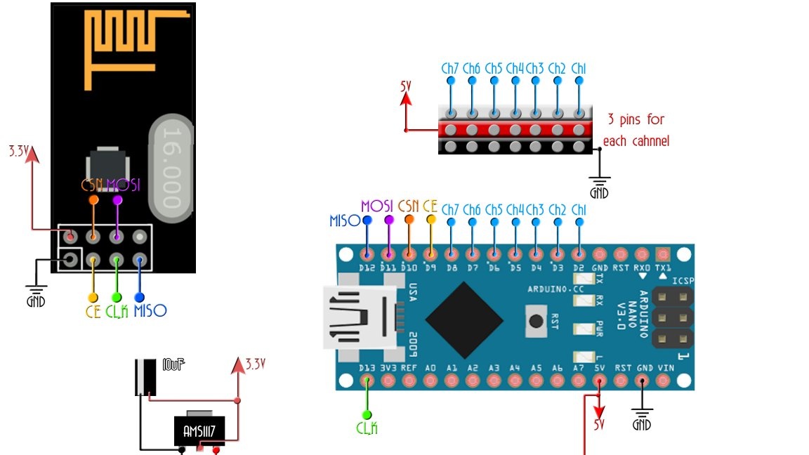
1 x NRF24l01 radio module with amplifier and antenna
9 x tact button 6 * 6 * 5 mm
Output resistors (see diagram)

For the receiver you will need:

1 x Arduino NANO / UNO / Pro Mini
1 x Radio Module NRF24l01
1 x AMS1117 3.3V voltage regulator
30 x pls combs
1 x breadboard
1 x 10 uF capacitor

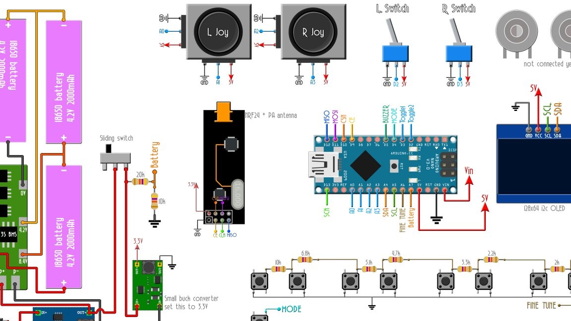
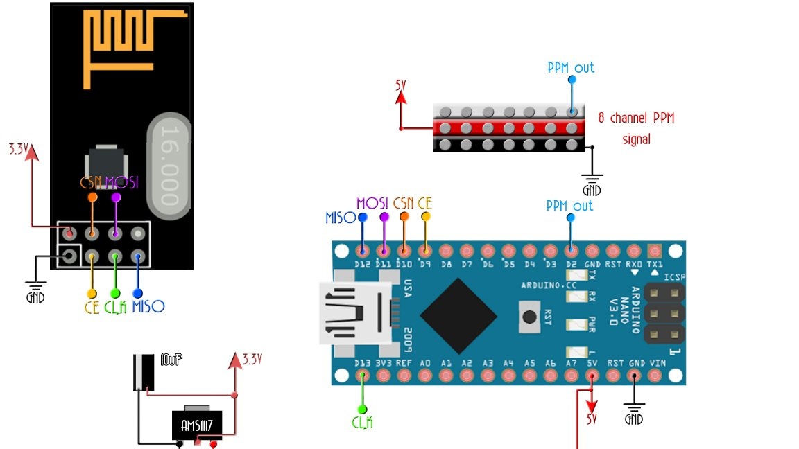
Below you can see a graphic image of all components and a diagram of their connection. Before assembly, buck converters must be configured, XL6009 to 12.6 V (this module is responsible for charging), LM2596 to 3.3 V (power to the radio module). Instead of LM2596, it is theoretically possible to use ASM117, according to the datasheet, the maximum input voltage of this stabilizer is 15 V, but it is advised not to apply it higher than 12 V. Apparently, based on these considerations, the author used another DC / DC converter. Instead, you can also use an adjustable stabilizer, for example LM317.


Housing

Radio Control Equipment on Arduino


The case consists of two main parts: the upper and lower. In addition, 9 buttons (8 for trimming and one mode button), 5 backups for buttons, a bezel of the display and a power slider are printed.The author printed a PLA with an eraser with 20% coverage, a 0.4 mm nozzle and a layer height of 0.3 mm. By the way, no one forbids the use of another case, you can just take a suitable box, glue it yourself or take a fairly large case from a Chinese toy, they are almost sold in bags on classified sites.


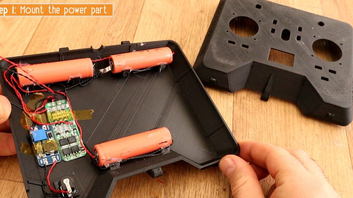
Transmitter Mounting

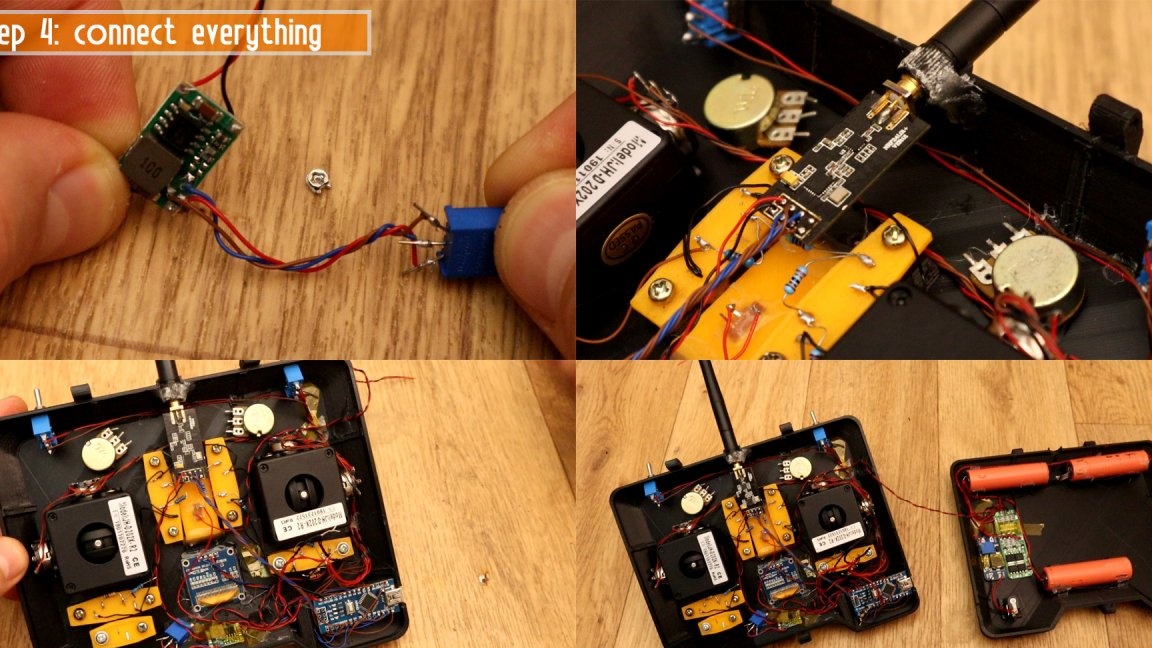
Batteries are connected in series. The author did this with soldering, I want to note that soldering cans of 18650 requires some skill, so if you have no such experience, buy batteries with already welded petals and solder to them. Also, the batteries according to the above scheme are soldered to the BMS module, the input of which is supplied with voltage from the XL6009 converter (MT3608 can be used instead). The BMS is responsible for evenly charging / discharging all the cans and turning off the power when the batteries are exhausted. Voltage can also be monitored using the display. The batteries are charged by a 9 V power supply with a current of not more than 3 A (maximum for XL6009). In fact, the charge current must be calculated depending on the capacity of the batteries and take the power supply with a slightly lower current or limit it. It is convenient to mount the modules in the housing with the help of "automobile" double-sided tape.


The clock buttons are installed on special platforms, after which they are attached with small screws to the corresponding supports inside the case. Here, in fact, everything is at the level of the designer and is well understood from the photo.


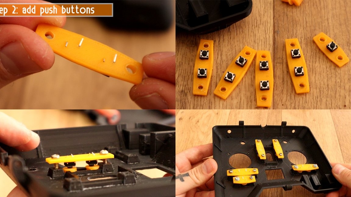
The buttons are interconnected by resistors, thus essentially leaving a small resistive keyboard, which allows you to use only one pin of the Arduino board. The wires are soldered to the joystick potentiometers, the extreme leads go to ground and 5 V, the average leads to the corresponding Arduino pin. I have plans to repeat this scheme, I have already experimented a bit and I can say that the code has the function of automatically inverting channels as needed, but I have not yet understood how the scheme determines this very need. This is to say that the channel inversion is essentially carried out by soldering the extreme conclusions in places. Such joysticks, at the time of writing, are sold in Ali at a price of about $ 7 apiece, whether this is up to you or not. Instead, you can use the joystick modules for arduino or joysticks from game controllers.

In fact, the joystick works as a divider, deflecting the handle, we change the voltage at the middle output of the potentiometer, and depending on this voltage, the arduino determines the deviation.
[center] [/ center]
Tumblers are also connected. Toggle switches are needed on-off, since the channel is discrete and has only two values ​​- 0 or 1, depending on whether the output of the arduino is attracted to the ground or to a 5V power supply. Moreover, the on-off switch is necessary, if you leave the output "hanging in the air", what would happen when using three positional, the controller does not understand what is happening and the value randomly jumps either 0 or 1 (in my experience). You can not set additional potentiometers, at the moment they are not involved. Or you can put and monitor the source page, perhaps the author will eventually post the updated firmware.


Next, an arduino, a radio module and a radio module power board are installed. As described above, it is necessary to set a voltage of 3.3 volts on it. It is almost impossible to do this using a standard variable resistor, so the author unsoldered it and soldered a multi-turn trimmer instead. Next, the display is mounted, and all components are connected to the arduino terminals according to the diagram.


Firmware

Arduino firmware has already been talked about 1000 times, at this point in time, the ability to do this while holding on to an arduino project is just as important by default as the ability to hold a soldering iron in your hands while holding something to solder.The code for the transmitter, receiver, necessary libraries and a file for 3D printing of the case can be downloaded in one archive at the end of the article.


Receiver


For the receiver, you will need another Arduino board, a radio module (without an antenna, telemetry is still not implemented here) and a 3.3 volt stabilizer. The receiver is soldered to the breadboard. The power of the receiver is carried out in the same way as the power of any other factory receiver, from a special output of the speed controller.


On my own, I want to add that instead of the standard antenna of this module, it is desirable to solder the same antenna that is installed in the module with an amplifier (only without a housing). This will not particularly affect the reception range, but will significantly affect the reception quality depending on the position of the controlled model in different planes. For modern receivers and transmitters, for this purpose, even two antennas are installed, which are located perpendicular to each other.


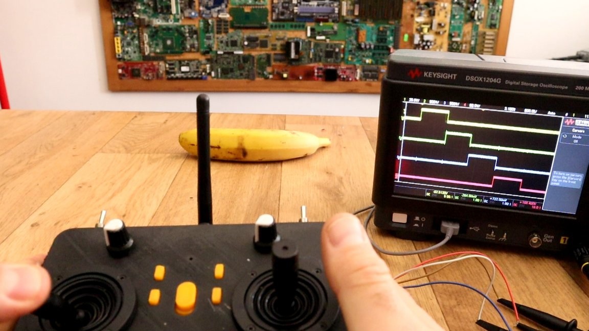
In addition, the author has implemented a very important function - output from the PPM receiver signal. Schematically, nothing changes, you just need to fill in another firmware, the PPM signal is output in the same way as in most factory receivers - from the first channel (gas).


That's all. Personally, I really liked the project, and as I already said, plans to repeat it in the case from the remote control of a children's toy. In the menu you can select the mode from linear to exponential and fine-tune the value of each stick. Keep in mind that the average value of each channel should be 127.


You can download everything you need here.

All success in the work!
8.9
8.6
8.6

Add a comment

    • smilesmilesxaxaokdontknowyahoonea
      bossscratchfoolyesyes-yesaggressivesecret
      sorrydancedance2dance3pardonhelpdrinks
      stopfriendsgoodgoodgoodwhistleswoontongue
      smokeclappingcraydeclarederisivedon-t_mentiondownload
      heatirefullaugh1mdameetingmoskingnegative
      not_ipopcornpunishreadscarescaressearch
      tauntthank_youthisto_clueumnikacuteagree
      badbeeeblack_eyeblum3blushboastboredom
      censoredpleasantrysecret2threatenvictoryyusun_bespectacled
      shokrespektlolprevedwelcomekrutoyya_za
      ya_dobryihelperne_huliganne_othodifludbanclose
30 comments
feonor12 correctly writes that unused inputs must be pulled either to the ground or to power. I began to adhere to this rule as soon as I learned to work with CMOS chips. Oh, how long ago it was ... And in microcontrollers, of course, no one has canceled this rule.
thanks a lot!!!!!
Author
In the compilation process, I also reassigned some variables, and also wrote that there was little memory, although it was immediately written that the sketch uses 77% of the memory. The sketch is clumsy, no one denies, but it works. The main thing that compiled. Build a test circuit and check how it works, problems need to be solved as they become available. When you assemble the test circuit of the transmitter - all unused channels, be it joysticks, a toggle switch or keyboard, in general, everything that is not connected must be tied to ground or to 5V, if you leave the device "hanging in the air" it will not work adequately, with this collided when repeated.

Z.Y. Register and you can.
Guest Andrew
it almost turned out like in your photo.
only now swears, in short, here
C: \ Users \ mozga \ Documents \ Arduino \ library \ Adafruit_GFX_Library \ Adafruit_GFX.cpp: in the member function 'boolean value Adafruit_GFX_Button :: contains (int16_t, int16_t)':

C: \ Users \ mozga \ Documents \ Arduino \ library \ Adafruit_GFX_Library \ Adafruit_GFX.cpp: 1120: 28: warning: comparison between signed and unsigned integer expressions [-Wsign-compare]

return ((x> = _x1) && (x <(_ x1 + _w)) &&

                             ^

C: \ Users \ mozga \ Documents \ Arduino \ library \ Adafruit_GFX_Library \ Adafruit_GFX.cpp: 1121: 28: warning: comparison between signed and unsigned integer expressions [-Wsign-compare]

(y> = _y1) && (y <(_ y1 + _h)));
eventually compilation completed
and writes not enough memory and the program may not work stably.
sorry, I can’t put a photo here.
Author
Remove / put two slashes.

#define SSD1306_128_64
// #define SSD1306_128_32
// #define SSD1306_96_16

This is how it should be.
Guest Andrew
thanks a lot.
do not swear much.
Now I will google, which means:
(Comment out the second and uncomment the first.)
Author
For two, damn it, google minutes. In the Adafruit_SSD1306.h file you need to find these lines

// #define SSD1306_128_64
#define SSD1306_128_32
// #define SSD1306_96_16

comment out the second and uncomment the first.
Author
Listen, I did not write this code and am not a specialist in programming. What I knew, then prompted, it does not suit you. It works for the author, I collected it - it works for me too. It doesn’t work for you, so the error is not in the code or in the library. Contact the thematic forum, go to the source and write to the author, or wait until someone who knows here answers. I said that I did not know what was the matter, what else was needed from me, so that I would drop everything and begin to deal with the problem for you? Soorry, no.
Guest Andrew
" thanks for the help"
error in the Adafruit_SSD1306.h library
And I have a problem of "private order."
that's what gives out.
Transmitter_code: 102: 2: error: #error ("Incorrect height, fix this in Adafruit_SSD1306.h!");
maybe what number or letter should be changed there, but I don’t know
Author
Then I don’t know, everything compiled and was stitched. Now I checked for the sake of interest, everything was compiled too. So a private problem.

Guest Andrew
Adafruit_SSD1306-master library
installed the arduino ide program in the program itself
Author
Is there an error during compilation? He is cursing at the display library. Did you install the Adafruit_SSD1306-master library from the archive on Wednesday?
Guest Andrew
Hello.
I decided to check the sketches first. PPM and PWM receivers (read.)
I started checking the transmitter, it gives an error.
#error ("Height incorrect, please fix this in the Adafruit_SSD1306.h!");
Google translator translated.
#error ("Height is incorrect, please correct this in Adafruit_SSD1306.h!");
And what should I do now, I don’t even know ..............
Author
Hello. In general, I have neither the time nor the desire to finish the app in the near future so that I can write an article on it, but for a long time I drew a signet of the receiver who needs to be taken. I did not collect the board, but I checked it several times, everything seems to be correct. A few words that there would be no questions:
The radio module stabilizer is soldered in smd on the board (ASM1117 at 3.3 V, switching on by datasheet). If it will work unstably or for a short distance - hang 10 microfarads of conders directly on the module's power contacts (I couldn’t find a place to shove on the board).
We solder the smd, then the jumpers, followed by the arduino (paws of programming to the comb of outputs), the second "floor" of the radio module, like I did in the flight controller. The radio module overlaps the reset button of the arduino, so I brought it to the back of the signet (just solder it from the arduino and solder it). If your programmer pulls the reset yourself, or you don’t plan to reflash after assembly, you can remove the button and the tracks from the watering can, the scarf will come out a few millimeters narrower and shorter (20x50 mm). In any case, the scarf came out very compact. On the radio module, it is desirable to cut the printed antenna and solder as on standard 2.4 GHz receivers (photo below). This will not affect the range, but reception will improve with different orientations in space. 5V power to any connector from WEIGHT regulator or external.
Set the finished board in a transparent heat shrink, you can pre-draw, print and insert a nameplate with the designation of contact groups. Or make a butebread like the same flight stabilizer.
Well, everything seems to be you can download a signet here.


Here is the stub. flight, an article on it in my profile.


Guest Vladislav
Write to help, I collected the sketch in pieces, since my native did not start, now everything works fine, Viber 0993482290
robot
help with the skatech. there are a lot of mistakes !!
Author
I do Appu in my free time even from free time, a tautology, but it's true.For there is a factory app flysky i6, this one, for the sake of sporting interest, I am collecting it. When I’ll completely finish it, I’ll collect the normal receiver - I’ll draw up everything in a separate article.
But so that you would not have doubts about its performance, here waved the aileron:

As you can see, it works. One channel connected, for example. The wire to the receiver is power, powered by charging from the phone.

Although there is much to develop, by and large it is in the software part, to realize the choice of the most noiseless channel, binding, to collect several receivers, add memory for at least 5 models. Even telemetry can be washed down if you want. But for this we need either the help of enthusiasts, or the Arduino language itself is better to learn, or the author to write, maybe this will interest him. I, in the near future, will definitely not do this.

And I already said about the food. 1 can of 18650 + MT3608 + ASM1117 + TP4056 with protection of ≈4-5 bucks. As an option, but there are many of them, at least from batteries.
Andrew1978
Show the video of your remote control ..... About Nonsense - nonsense may be for you, but this is 65% of the cost of the entire remote - three stubs, a charger and three lithiums ....
Author
No one bothers to organize meals otherwise. For some reason, everyone clings to nonsense, omitting the main nuance - these are ready-made “brains”, the receiver and transmitter on a standard PPM signal, and how to feed them and in which case to shove is the tenth thing. You can also power from one can through a boosting DC / DC converter, correcting the code to correctly indicate the charge of one can. So far I have been eating from the crown, for for permanent use I have not conceived my own version.
Andrew1978
What a perversion to feed the three lithiums with a remote control that uses 5v and 3.3v ....
Author
Author
Do you want to make a case yourself? This is a waste of time, normally it still won’t work out. On sites classified ads sell a bunch of remotes from toys, including pistol type. Sell ​​for a penny (the child killed the toy, but the remote control remains). Choose less massive and redo. Alteration is reduced to throwing out the entire filling and prying to the controls of linear potentiometers.
Another option is to buy an appu with a singed filling, but the whole mechanics. On the sites of modelers such from time to time pop up.
My appa will look something like this (the nameplate is test, then I'll make it more beautiful)
Guest Eugene
that's the mechanics and interests and there’s nothing to redraw with
Author
What for? Yes, and who is interfering, this is a matter of mechanics. Take the pistol console from the toy, modify it and it will be like that. You can take anything, a computer joystick for flight simulators, even a gamepad from Sonya. Here the main scheme.
I’m already assembling myself from a toy console.
Guest Eugene
pistol-type equipment would be made ...
Author
Just checked, everything opens and downloads. Perhaps you have some kind of ad blocker or something else.
If someone else has problems with downloading - write, I will turn to the administrator.
this one doesn't work here
Author
You can download everything you need here.

Click here
Author
You can download everything you need here.

Click here
and where is the sketch for the equipment

We advise you to read:

Hand it for the smartphone ...