
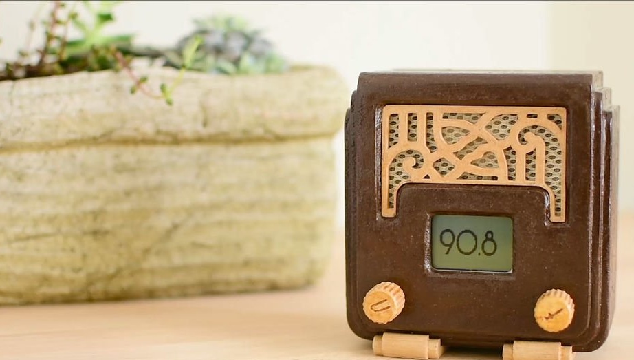
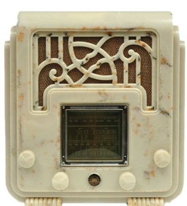
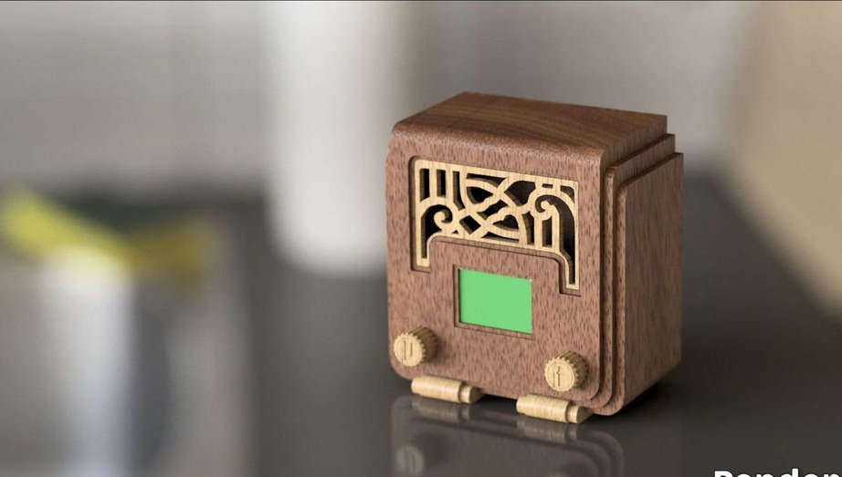
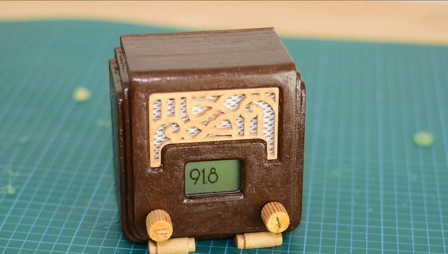
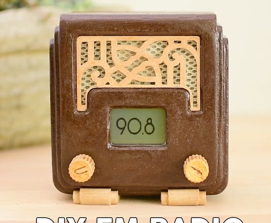
Once upon a time we collected our first unpretentious school-age radios from sets. Today, due to the development of modular design, to assemble a digital radio receiver will not be difficult even for people who are very far from amateur radio. The design of this receiver is based on the impressive 1935 AWA radio that the author stumbled upon in the book "Deco Radio: The Most Beautiful Radios Ever Made". The author was so impressed with his design that he wanted to have his own analogue.
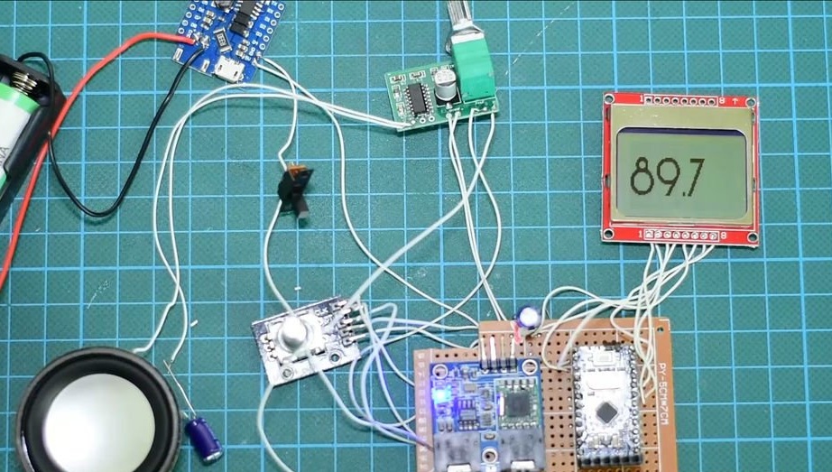
The design used a Nokia 5110 LCD display to display the frequency and an encoder to select it. The volume is controlled by a variable resistor built into the amplifier. To emphasize the design, the author also used an Art Deco font to display information on the display. The arduino code contains the function of remembering the last station you listen to (which was listened for more than five minutes).
Step 1: Components
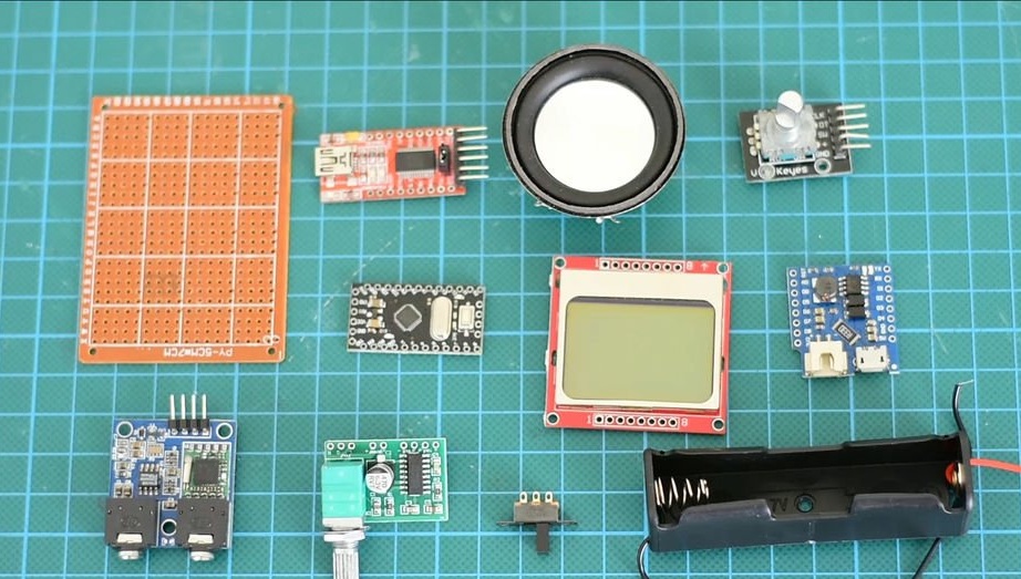
- Arduino Pro mini
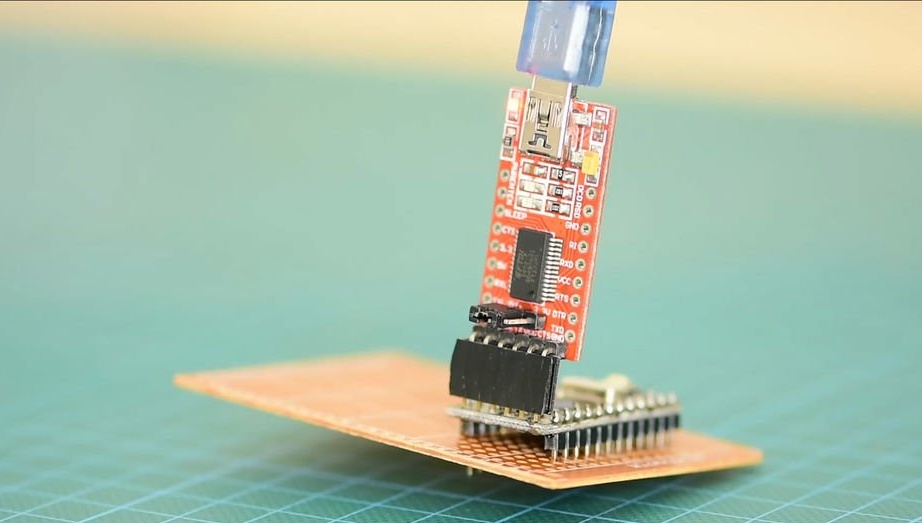
- FTDI Programmer
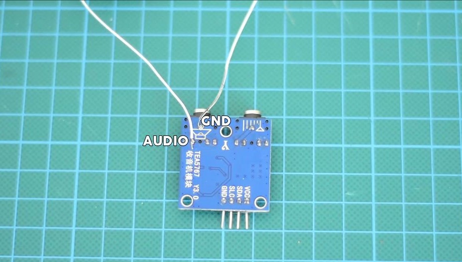
- TEA5767 FM Radio Module
- 3 watt speaker
- Amplifier Module PAM8403
- Encoder
- Nokia 5110 LCD
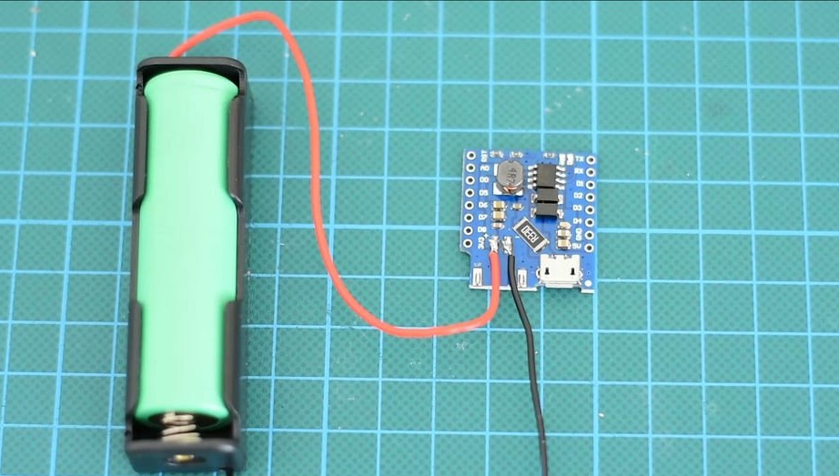
- Charge and battery protection board
- 18650 battery
- Holder 18650
- Switch
- Development Board 5x7 cm
- Connecting wires
- Fabric for speaker
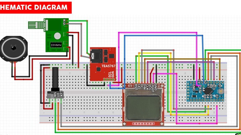
Step 2: Electronics
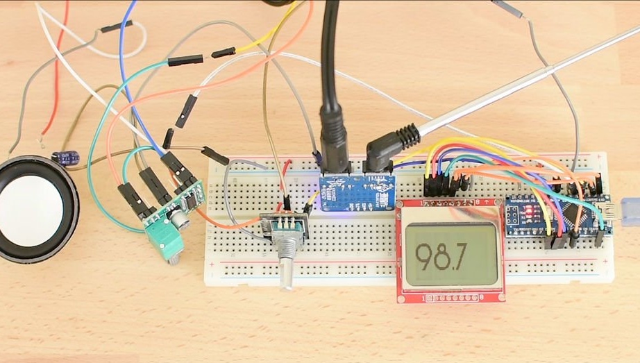
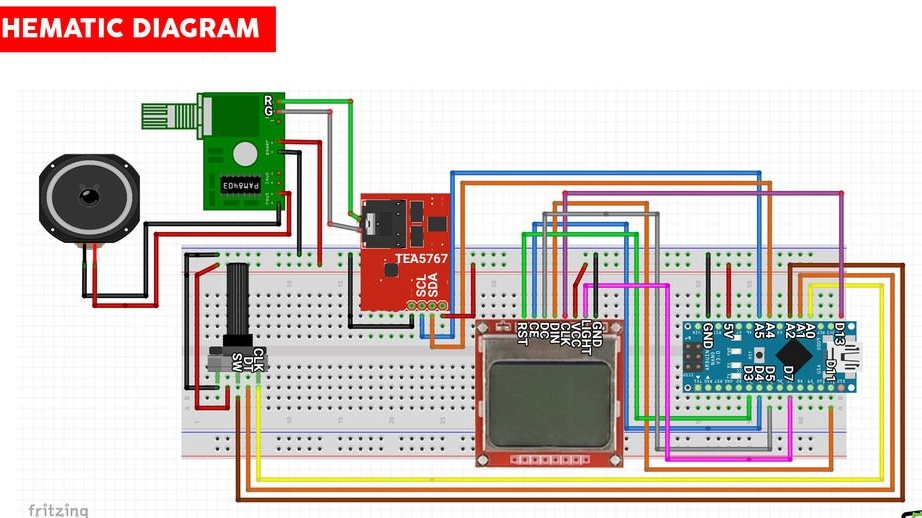
First of all, if you do not have much experience working with arduino, you should first assemble the circuit using a carefree breadboard. At the same time, for convenience, you can use Arduino Nano or UNO. Personally, I use Arduino UNO at the stage of debugging circuits, since it is convenient to use it together with the breadboard to connect the necessary components, practically without soldering. When the device is turned on, a logo should be displayed on the screen for several seconds, after which the frequency of the last station being listened is loaded from the EEPROM memory. By turning the encoder knob, you can adjust the frequency by changing stations.
When everything works well on the layout, you can proceed to the main assembly using the already more compact and cheaper Arduino PRO Mini, which, moreover, has lower consumption. But before that, let's see how everything will be located in the case.
Step 3: design the enclosure
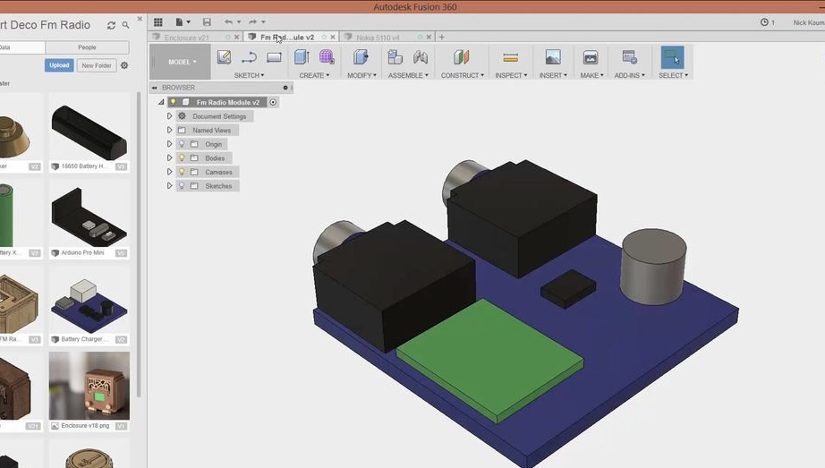
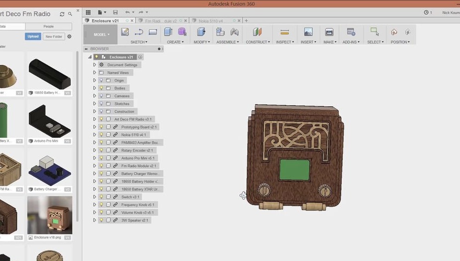
Three-dimensional model was developed in the free, but rather powerful program Fusion 360.
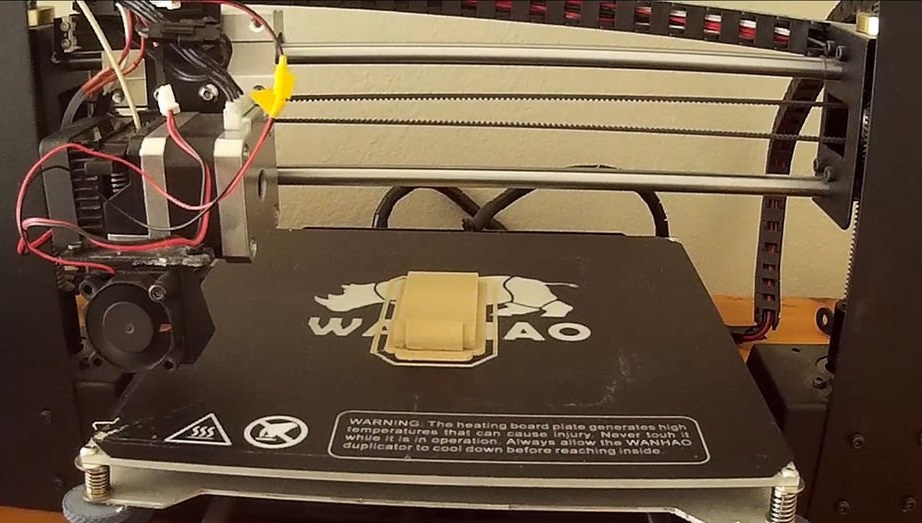
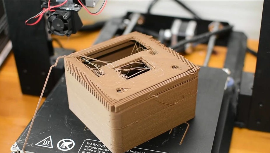
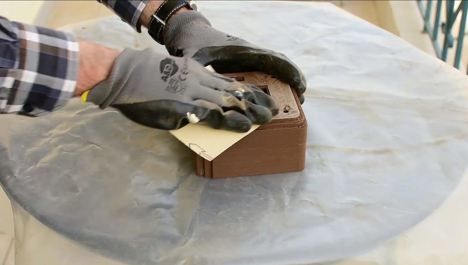
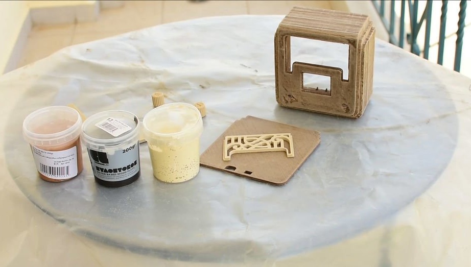
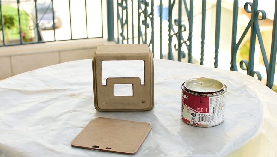
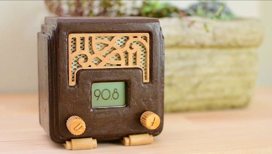
Step 4: 3D Printing and Processing
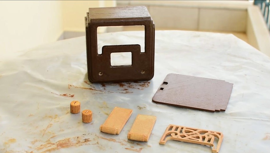
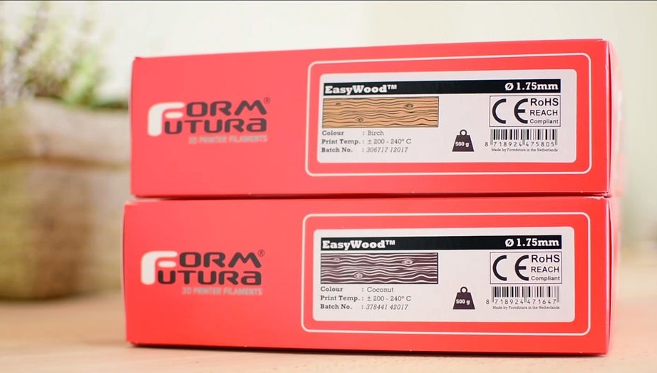
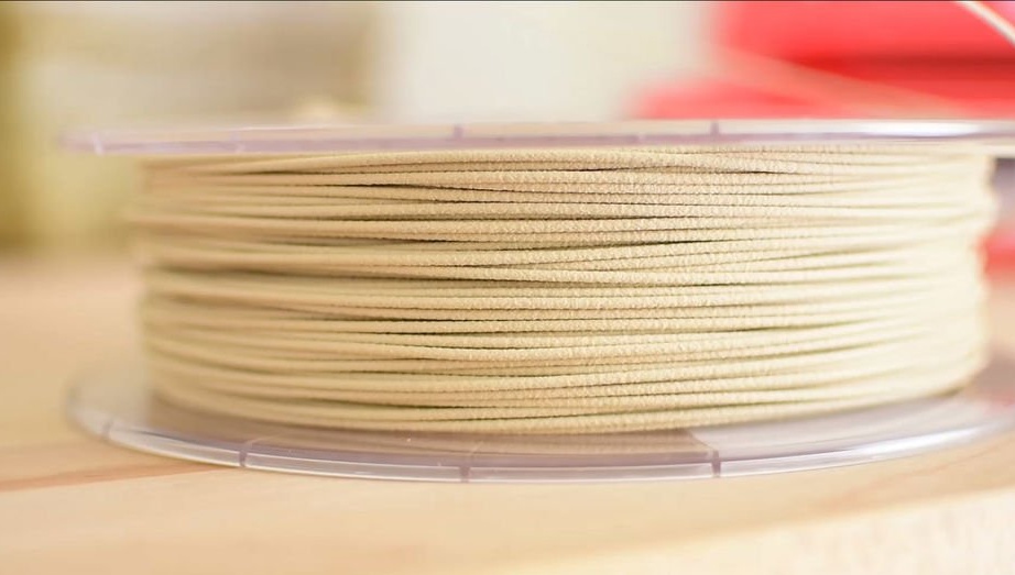
For printing, "wooden" FormFutura plastic was used. This is a rather unusual plastic, the peculiarity of which is that after printing the details look like a tree. However, when printing with this plastic, the author encountered a number of problems.Small parts printed without problems, but the case, the largest part, was not printed the first time. When trying to print it, the nozzle was constantly clogged, the situation was aggravated by regular power outages, because of which the author even had to buy a UPS for the printer. Ultimately, the casing was overprinted over the unfinished blank. Such a solution, however, is not quite a solution to the problem, only a one-time exit from the situation, so the question remains open. Since it didn’t succeed in printing successfully, the author decided to polish the body, putty putty for wood and varnish. Yes, this plastic is not just like wood, in fact it is fine wood dust mixed with an astringent plasticizer, so the parts printed by it are practically wooden, and lend themselves to processing methods for ordinary wood.
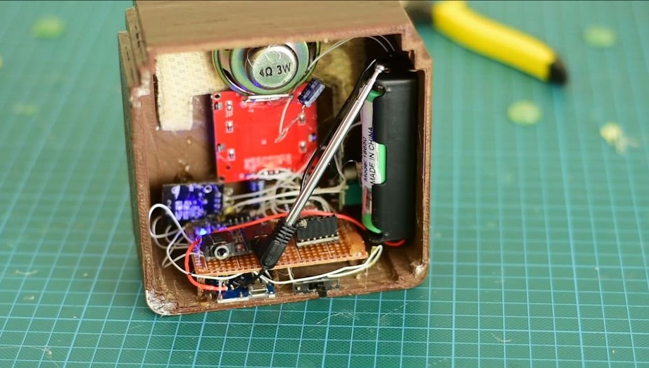
Step 5: Putting It All Together
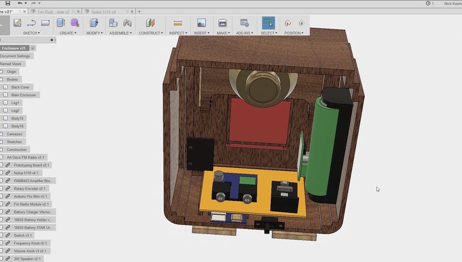
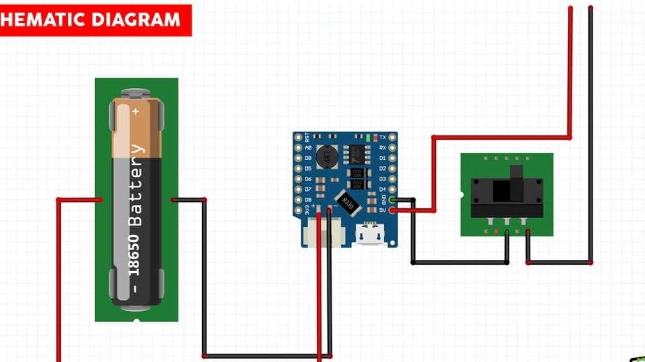
The next step is to install the electronics in the enclosure. Since everything has already been modeled in Fusion 360, there will be no problem with this. As you can see, each component has its own position in the housing. The first step was to solder the Arduino Pro Mini, after which the code was loaded into it. The next step is the power source. The project used a very convenient and compact Wemos board, which is also responsible for charging the battery, protecting it, and also increases the voltage for consumers to the required 5 volts. Instead, you can use the usual charge and protection module, and increase the voltage with a separate DC / DC converter (for example, TP4056 + MT3608).
Next, the remaining components are soldered, speaker, display, amplifier. Also, even though there are power capacitors on the amplifier module, it is advisable to add one more (the author set it to 330 microfarads, but it is possible to 1000). The quality (if 10% THD can be called quality) of the sound of the PAM8403 amplifier is very dependent on the power supply, as well as the operation of the radio module. When everything is soldered and tested, you can begin the final assembly. First of all, the author glued the grate, on top of it a radio fabric.
Push. Radio fabric is a specific thing, and they are not sold in every stall. However, in every female needlework store you can buy such a thing as canvas (fabric for cross-stitch). It is inexpensive and very well suited as a replacement for radio tissue, it comes in different colors. Take natural (not synthetic) and with the largest cell. By the way, it fits the design of this radio perfectly.
All other boards are fixed in place using hot-melt adhesive. You can spit a lot on hot melt glue, but for these purposes it is really well suited, given that most modules do not have holes for fastening. Although I prefer to use double-sided "car" tape for these purposes.
Step 6: Firmware
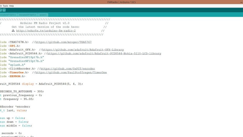
This step should be placed higher, since you need to flash it at the debugging stage. The main idea of the code is this: when the encoder knob is rotated, the frequency is scanned, when the encoder knob remains at the same position for more than 1 second - this frequency is set for the FM receiver module.
if (currentMillis - previousMillis> interval)
  {
    if (frequency! = previous_frequency)
    {
      previous_frequency = frequency;
      radio.selectFrequency (frequency);
      seconds = 0;
    } else
It takes about 1 second for the FM radio module to tune to a new frequency, so you won’t be able to change the frequency in real time by turning the encoder knob, because in this case, the tincture of the receiver will be very slow.
After setting the frequency for the receiver, the countdown begins. After 5 minutes, the frequency is stored in the EEPROM memory.
The code, as well as the files for printing, can be downloaded in one archive at the end of the article.
else
    {
      seconds ++;
      if (seconds == SECONDS_TO_AUTOSAVE)
      {
          float read_frequency = readFrequencyFromEEPROM ();
          if (read_frequency! = frequency)
          {
            Serial.println ("loop (): Saving new frequency to EEPROM");
            writeFrequencyToEEPROM (& frequency);
          }
      }
    }
The code, as well as the files for printing, can be downloaded in one archive at the end of the article.
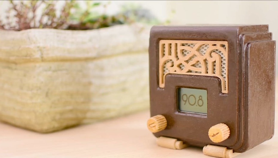
Step 7: Conclusion
We are very lucky that we live in an era when we ourselves can build whatever we want! We have the tools and resources to create everything we want in a matter of weeks and at low cost.

From myself I want to make a small note on the project.To turn on the radio, use a small slide switch located on the back of the case. The PAM8403 amplifier modules have not just a variable resistor for adjusting the volume, but a resistor combined with a switch (at least the ones that came across to me). That is, in the extreme left position, the switch is in the "off" position, we begin to turn it - click, turn it on, and then the volume is already adjusted. I think everyone understood what I’m talking about on all Chinese radios. So, what am I doing. This switch supplies power to the amplifier module. I propose the following: cut the tracks that fit the switch and short-circuit, thus excluding the switch from the circuit. And to the heels of the switch, solder the wires into the battery gap, thus making the use of the receiver more "usability".
Download archive with 3D models and firmware
That's all, all success in your work!