Greetings to fans to make do it yourself .
I needed a charger for the car’s battery. ATX is from PC, but PWM is not tl494, but 6105, which, unlike 494, is for conversion into an adjustable hemorrhoid ... Output - you need a DC –DC converter. Order from China for a long time and "cat in a poke."
The choice fell on the dc – dc boosting scheme based on UC 3843.
It was assembled in the shortest possible time (all elements are available and budget) and tested.
It turned out not a bad converter, but something did not suit. What? I do not know…
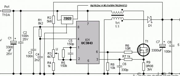
And then I came across a similar circuit on the same chip, but a step-down and step-up converter. It was only necessary to change the inductor to the transformer (which was also found in the old ATX), and recount some resistances.
I think there is no need to paint the operation of the circuit, everything has been described for a long time for us ...
I can only say that a transformer on a ferrite ring is wound with a wire of 1.2 mm by two wires in one direction of 24 turns, the beginning of the windings is marked with dots on the diagram, it is important to observe. That is, the circuit has a galvanic isolation, with an input voltage of 9-18 volts. It is possible to reduce the input voltage if you feed autonomously from 7 to 18 volts, but I don’t need this. And a little strained selection of R9 as a result of experiments, three resistors of 0.1 Ohm 5 W were installed in parallel, something like 0.03 Ohm 5 W was obtained in parallel. I think up to 10 amperes will master with this ATX ... Although ...
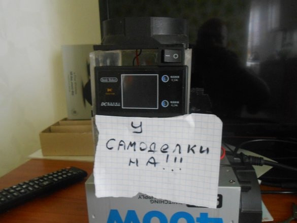
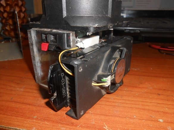
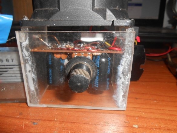
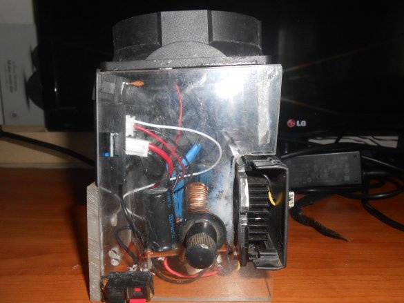
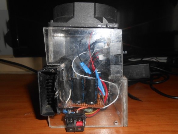
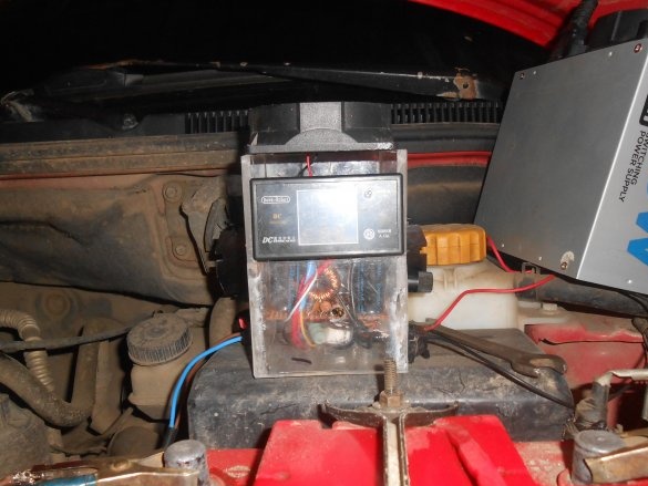
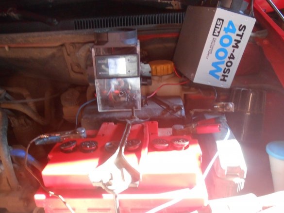
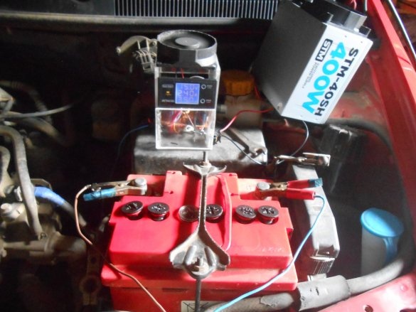
The result is such a pyramid (the first option without a voltammeter).
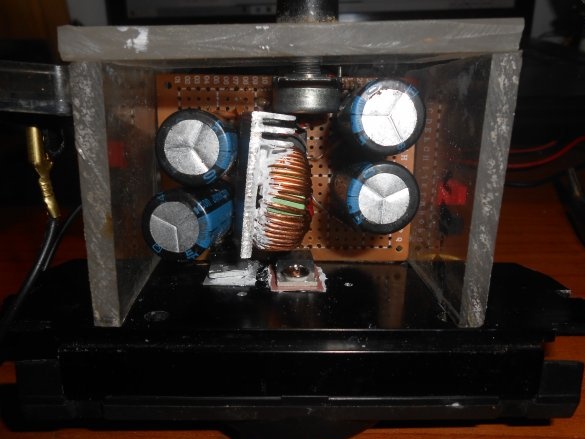
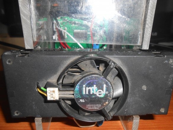
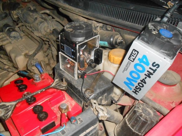
The key (irf 3205), the Schottky diode (from ATX sbl 3040) and 7809 installed on a radiator with a cooler from an old PC
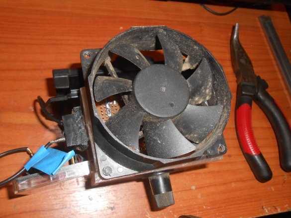
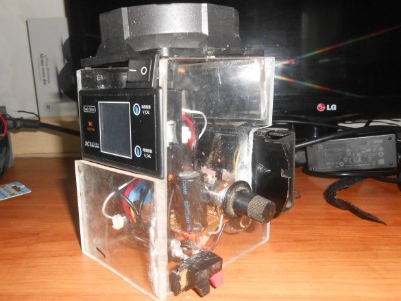
The cooler from the ATX PSU is on top, in the first version it was from the bottom.
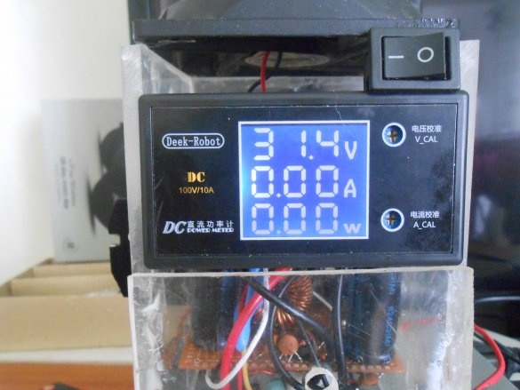
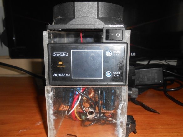
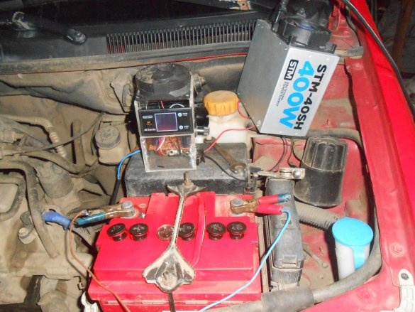
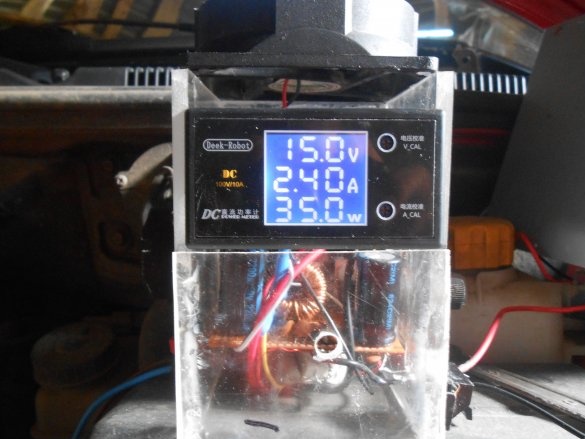
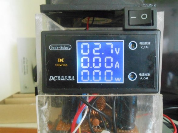
Here is the second option with a multimeter:
Charge the battery
Charges without problems, only the throttle heats up within the normal range.
Output Voltage Parameters:
minimum 2.7 volts
maximum 31 volts, the output voltage depends on the calculation of resistors R2, R3, R4, it is necessary that there are 2.5 volts or less on 2 pin of the microcircuit (on 2 pin, the duty cycle (width) of the pulses and, accordingly, the output voltage are adjusted). otherwise, the 6 pin IC will not generate a PWM signal.In my case, R2 is 550 Om, R3 is 5 KOm, R4 is 550 Om.
Now the soul lies with the transducer, and you can use it in nature from auto or connect a laptop, etc.
Good luck to all!


