

Good day to all. I bring to your attention a manufacturing variant of a fairly widespread (judging by its repetition and descriptions on the Internet) and simple design of the device for checking the windings of transformers, inductors, electric motors, relays and other coils with inductances from 200 μH to 2 H. The scheme and a detailed description of the principle of its operation were published in the journal "Radio" No. 7 for 1990, pages 68-69, by I. Pazdnikov.
The idea was to assemble this device from the various after disassembling electronic rubbish details. Make the appliance relatively compact and easy to use. To be able to quickly repeat the design, use a cheap standard product from the store as a case.
With this instrument, you can determine the integrity or rupture of the windings, inter-turn short circuits of the coils, the health of p-n junctions of silicon semiconductors.
With this instrument, you can determine the integrity or rupture of the windings, inter-turn short circuits of the coils, the health of p-n junctions of silicon semiconductors.
In this design used:
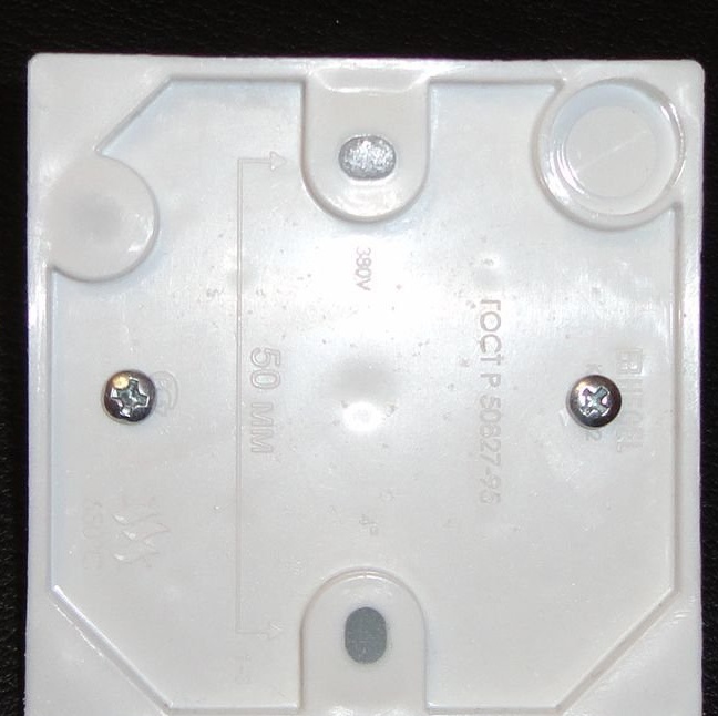
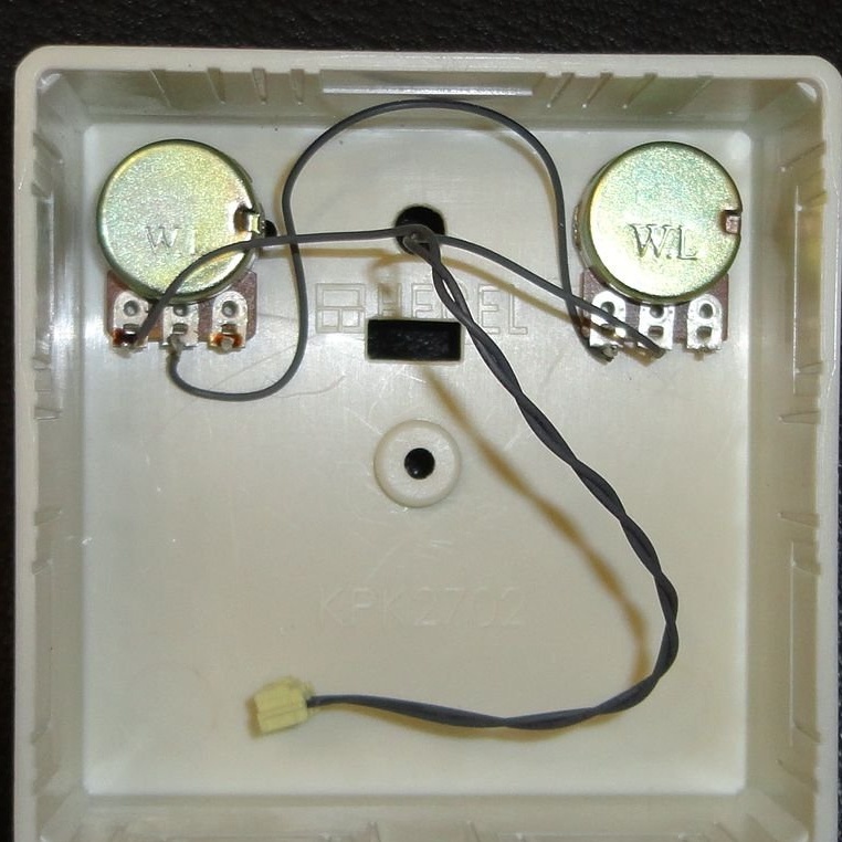
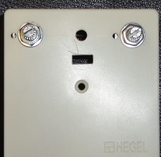
- Connection box 75x75x30mm "HEGEL".
- Mounting wire.
- Foiled fiberglass 68x68mm.
- Screws M3.
- Racks for 10mm boards.
- Radio parts according to the scheme.
Of the tools used:
- Drill.
- Soldering iron.
- Thermo-glue gun.
- Screwdriver, wire cutters, etc.
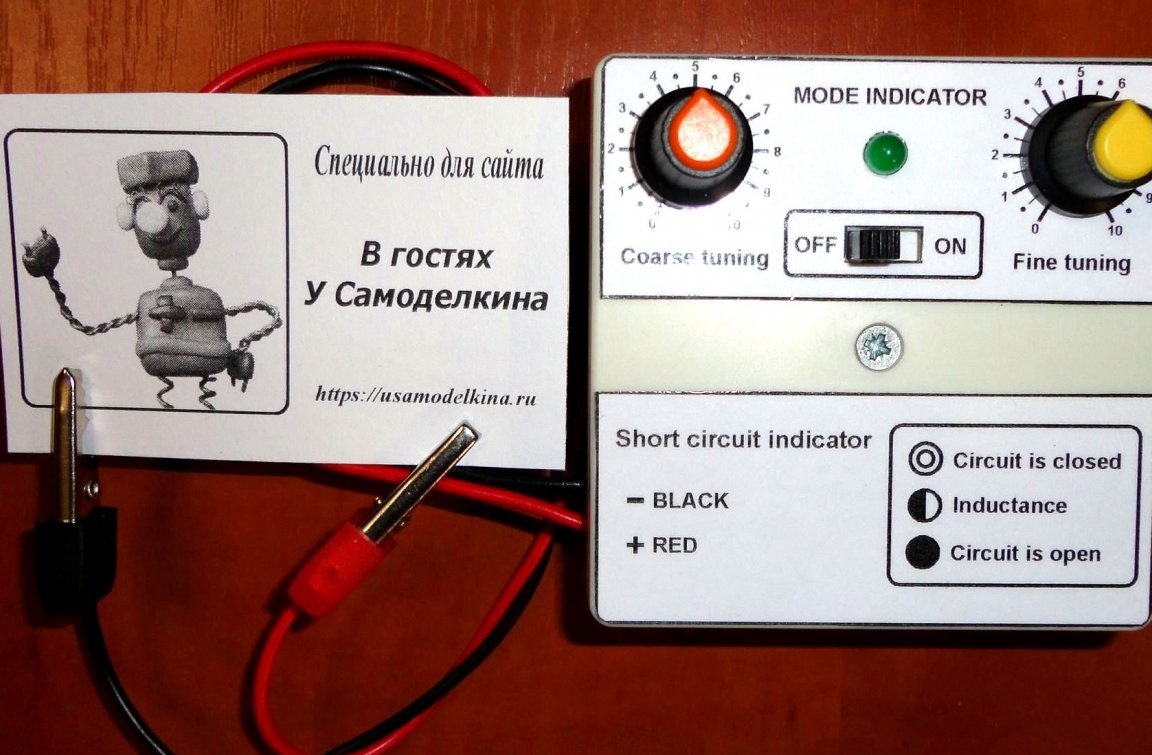
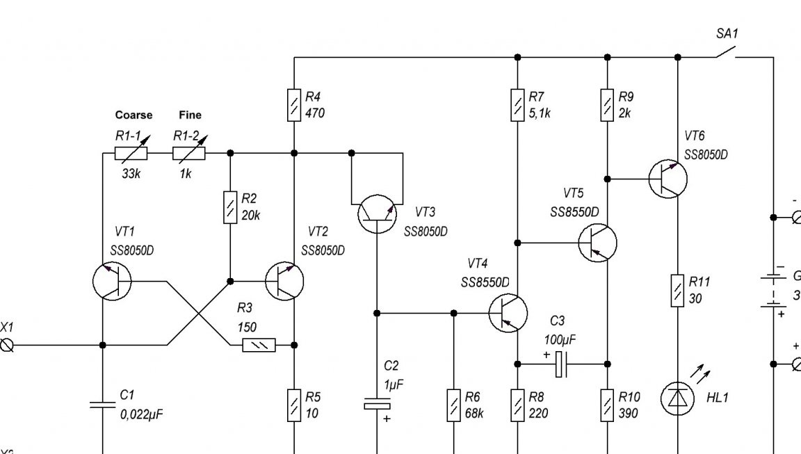
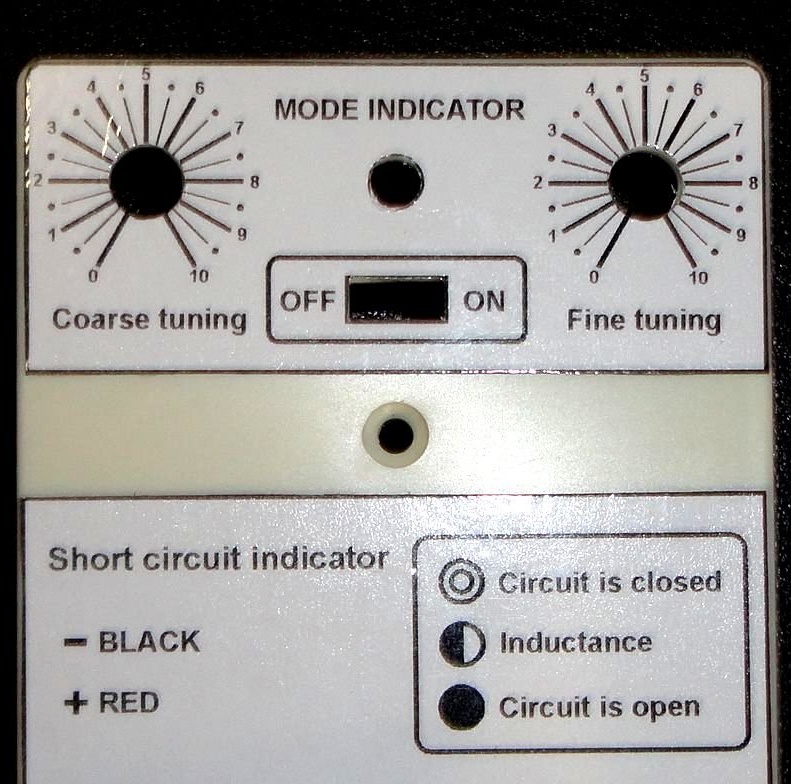
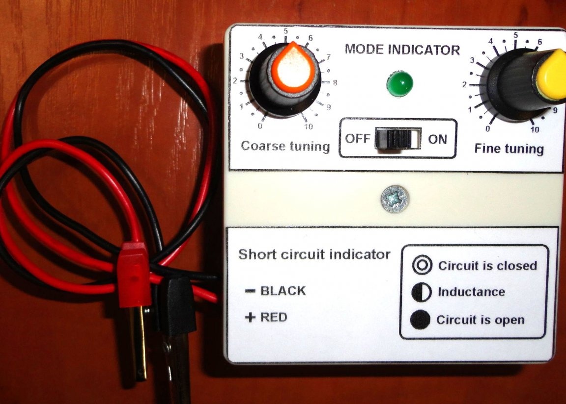
In I. Pazdnikov’s scheme, some details were replaced with the ones I had available. Added smooth tuning resistor. In order to save battery, the bulb is replaced by an LED. For the convenience of checking and adjusting, additional power contacts are displayed. Which, if necessary, can be output to the connector for connecting a network adapter (if there is no battery).
Schematic diagram of the device, according to the parts used.
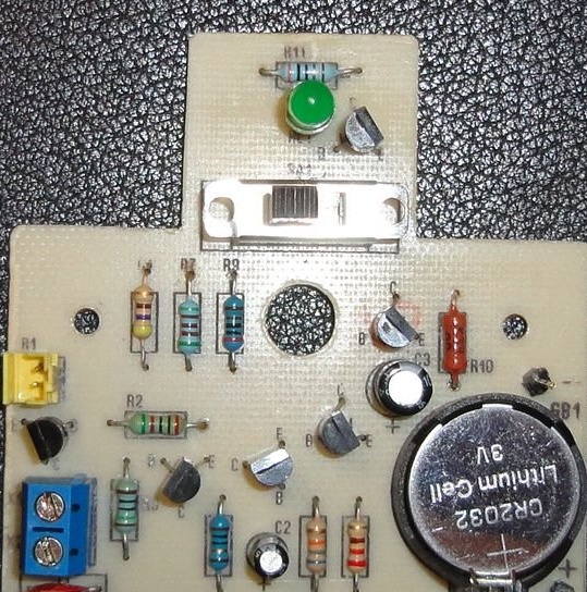
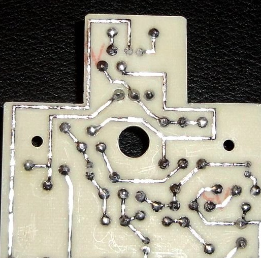
The printed circuit board is made under the case of the junction box, from fiberglass 68x68mm. The drill for the transistor legs is made symmetrical, which makes it possible to install transistors in the KT-13 and TO-92 (KT-26) housings without problems. The LED is mounted on a plastic support. The wiring of the board is presented on the part of the radio components.
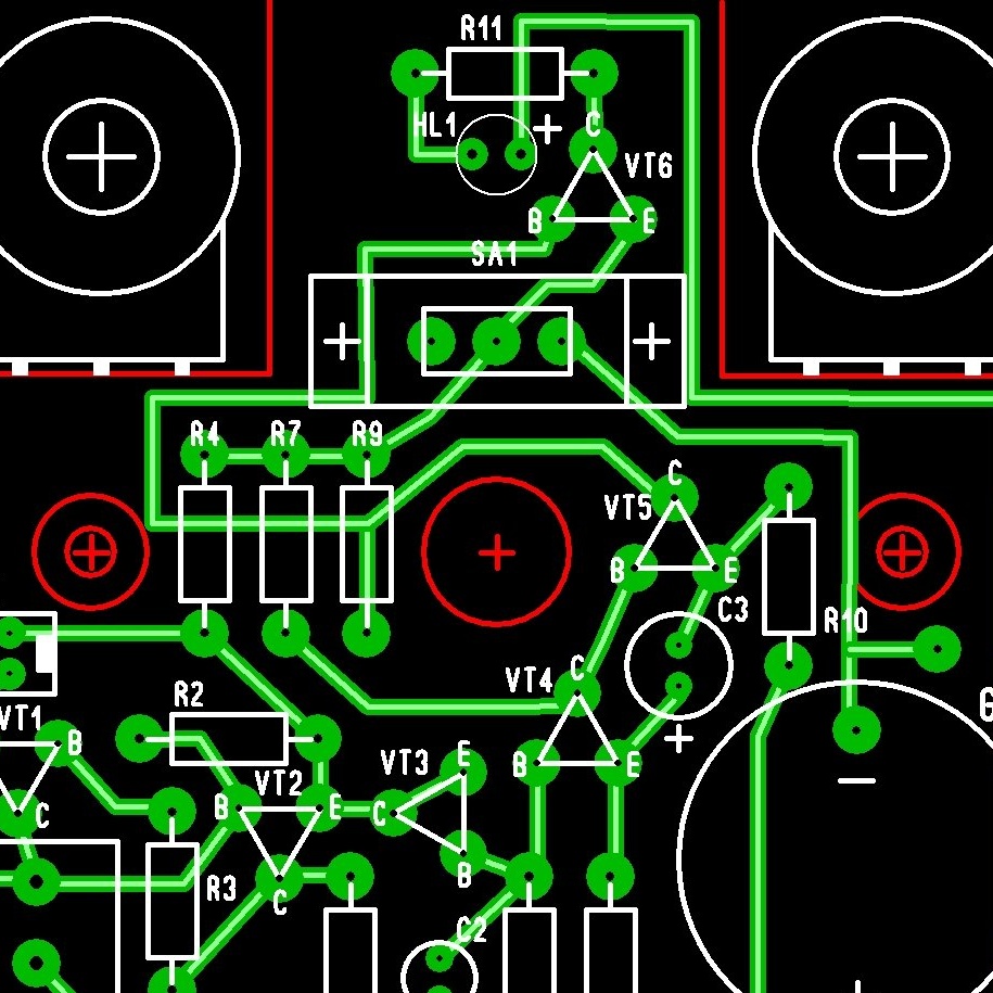
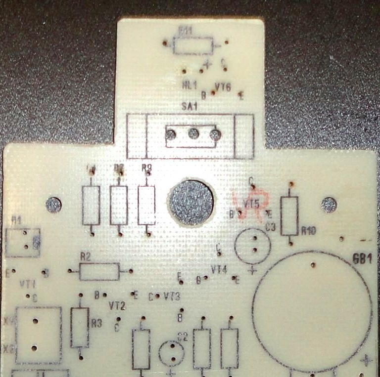
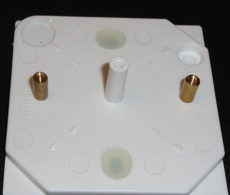
Mounting racks are installed on the bottom of the junction box housing. The corresponding holes are cut in the upper part (according to the stencil of the printed circuit board). Factory mounting holes are filled with hot glue.
To protect against dust and debris, a “skirt” cut from thin plastic is glued onto the switch slider.
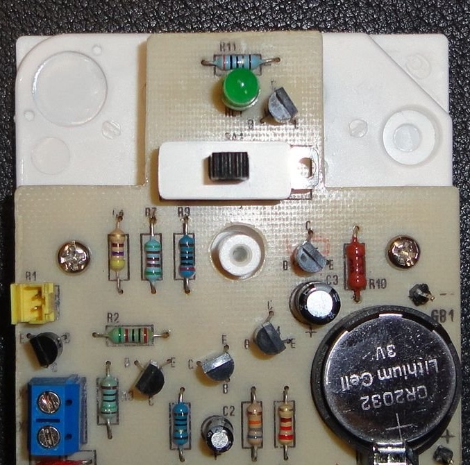
For ease of assembly, variable resistors are connected using a connector. For easy replacement, probe wires are connected via a terminal block.
The adjustment scales are designed for imported variable resistors with a shaft rotation angle of 300 degrees.
For probes, a multi-colored mounting wire, about 30 cm long, and crocodile clips are used.
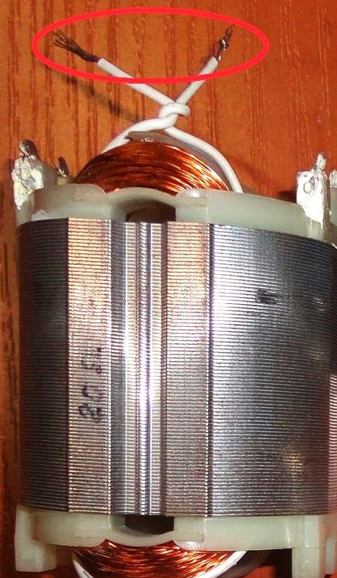
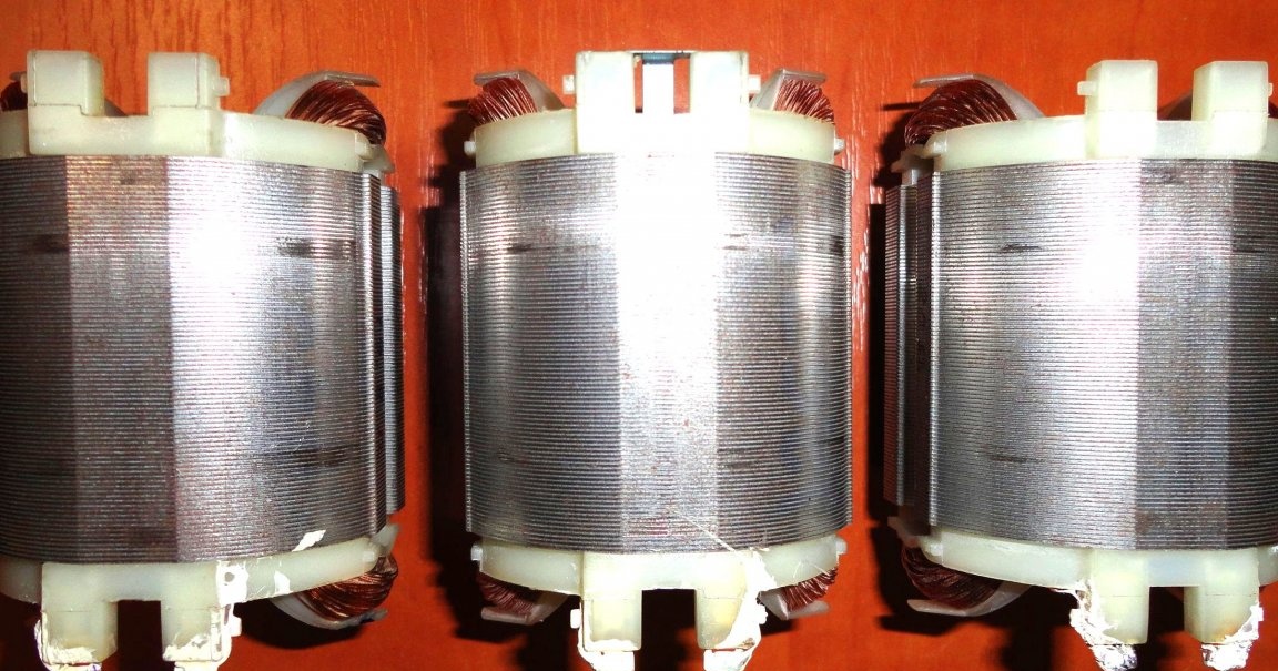
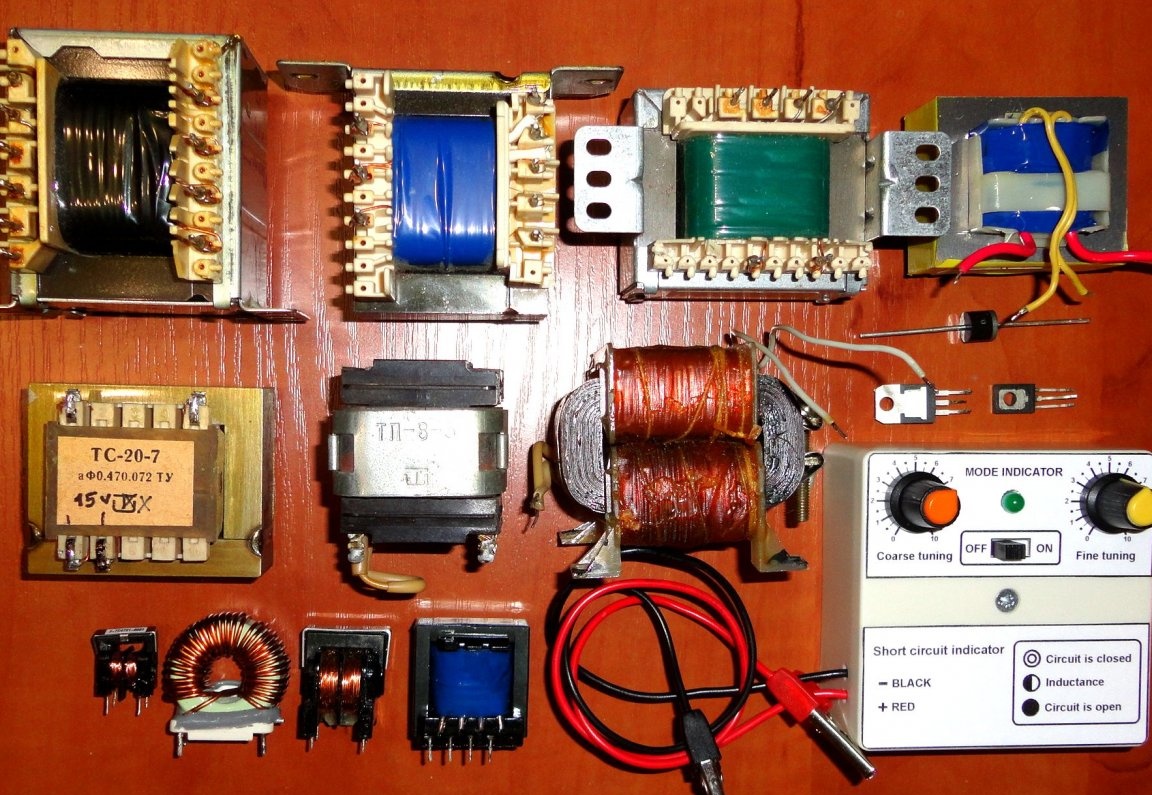
The resulting device was tested on the available transformers, diodes, transistors, inductors, stators and motor anchor. For simplicity of the scheme used, he showed a pretty good result.
Description of the results of tests of this "toy".
Crocodiles are open - the LED is off, regardless of the position of the controls.
"Crocodiles" are closed - the LED is constantly on, regardless of the position of the regulators.
When connected to the stator winding, the position of the regulators is selected that is closest to the transition from constant burning of the LED to the beginning of its blinking (the start of generation). When an additional turn is closed on the stator, the LED is constantly on, showing inter-turn closure (generation failure). With a strong decrease in resistance R1, the blinking of the LED can resume, but with a lower frequency.
Therefore, it is convenient to compare the state of the windings with each other or along the model with the same position of the regulators.
When checking the anchors, the probes were connected directly to the collector brushes. Next, the start mode of the LED flashing is set. The anchor is rotated a full turn. If the LED flashing is stable in all positions of the collector, then the anchor is most likely alive. When even adjacent collector lamellas are shorted together, the LED starts to light constantly, indicating a short. I didn’t have any really killed anchors at hand. So, the result is most likely very likely. What is connected with the peculiarities of the armature winding.
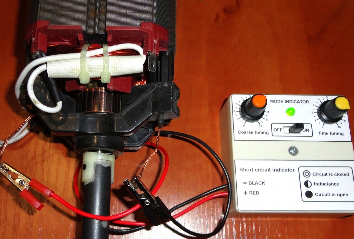
When testing transformers, the device was connected to the highest voltage winding. Further actions as when checking stators. When a winding closes, the device shows a short circuit - the LED is on continuously. The throttle was checked similarly.
When checking p-n junctions (+ to the anode - to the cathode), the indicator shows the following:
- The LED is on regardless of the position of the controls: p-n junction is broken.
- The LED does not light regardless of the position of the controls: the p-n junction is blown.
- The LED flashes - the p-n junction is operational.
If it becomes necessary to check frequently found products, then thanks to the successfully obtained dials of regulators, it will be possible to compose a convenient cheat sheet in the form of a table. There is no need to have a comparative sample on hand. In general, for use in home this appliance can be quite useful in conditions. Further time will tell.
If something is missing in the description, I hope these nuances can be considered in the submitted photos. I apologize in advance for possible errors and typos.
If you need additional information, write to the post office, I will try to be sure to answer. Feedback, ideas, suggestions for improvements to the design and comments are very welcome.
December 2019