
This is not the first work of a master in making fantastic weapons of space pirates. He made the very first blaster from a gun for polyurethane foam and some radio components.
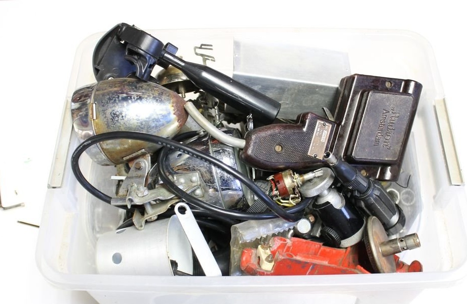
Then there were various models of robots, spaceships, etc. All these homemade What unites them is that they are made mainly of secondary parts. Radio tubes, LEDs, cases from which devices, metal staples, plates, etc., in the presence of imagination, everything will come in handy.
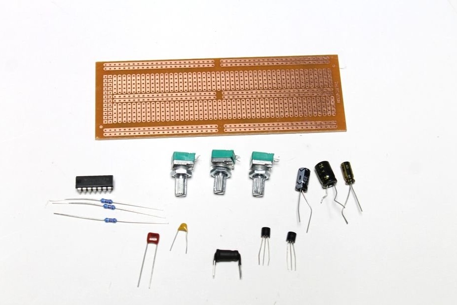
Tools and materials:
-Trigger CD40106BE;
-Potentiometers;
-Capacitors;
-Resistors;
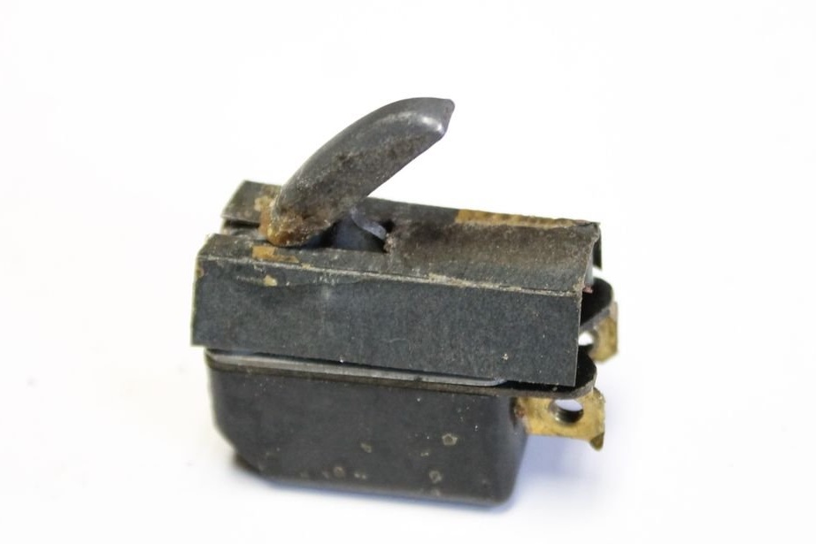
-Switch;
-Wire;
-Speaker;
-Soldering accessories;
-Bread board;
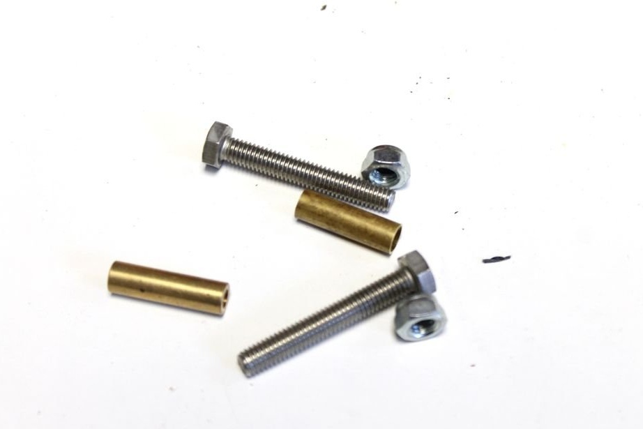
-Fasteners;
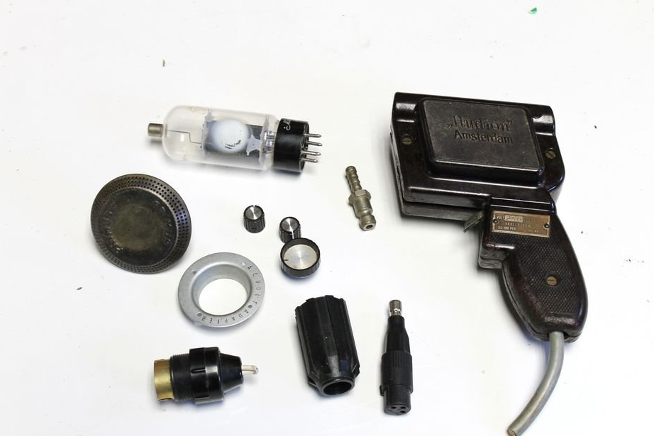
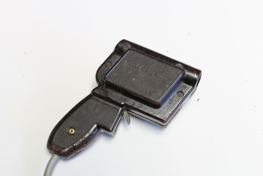
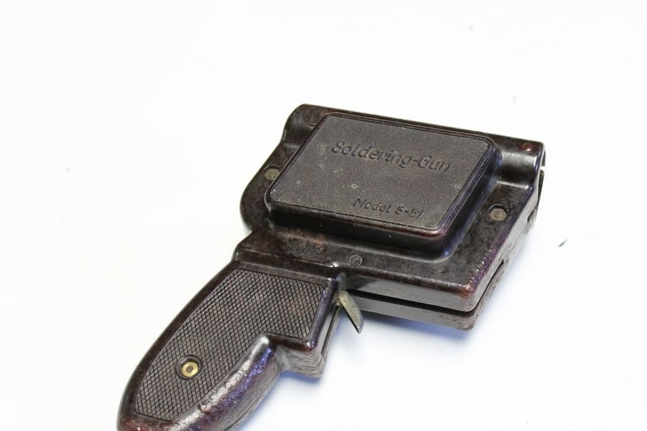
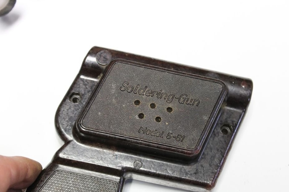
-Case from a soldering iron;
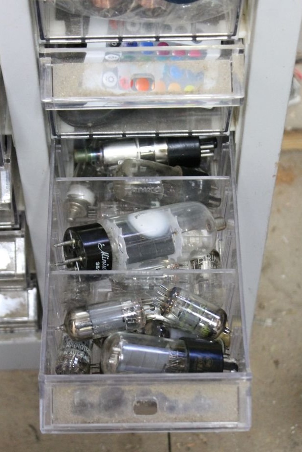
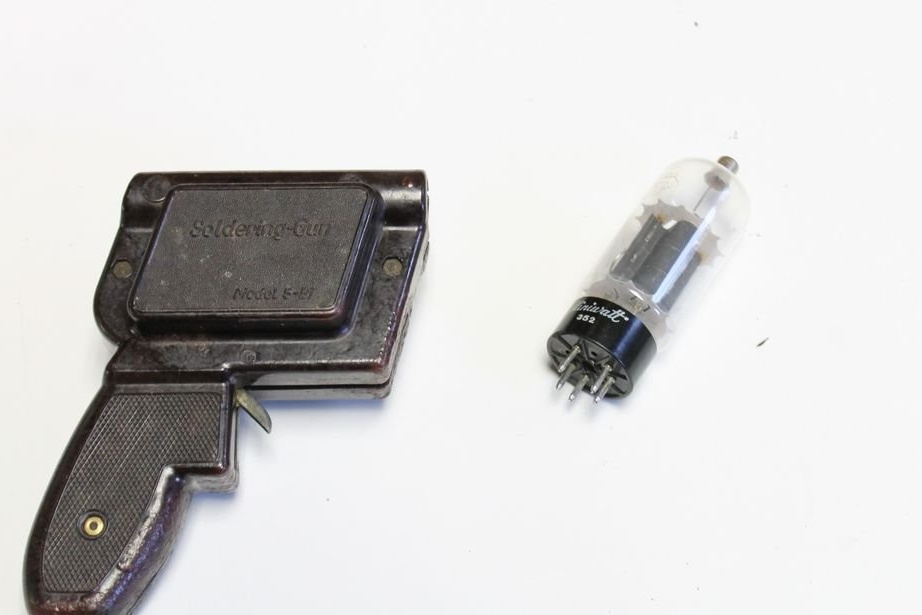
- Radiolamp;
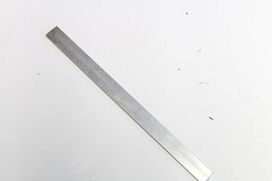
-Aluminum plate;
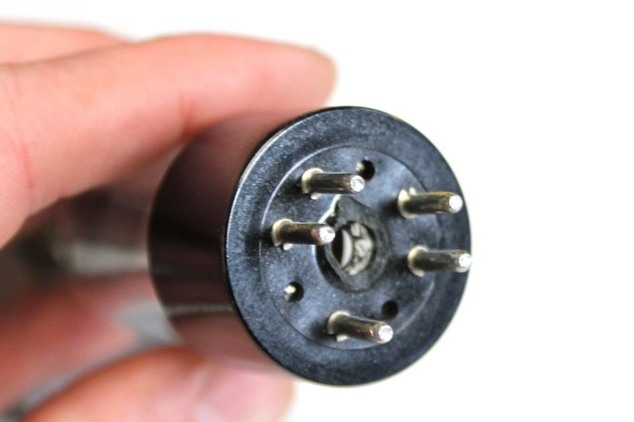
-Plug from an old microphone;
-Copper tube;
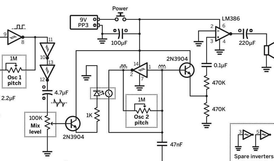
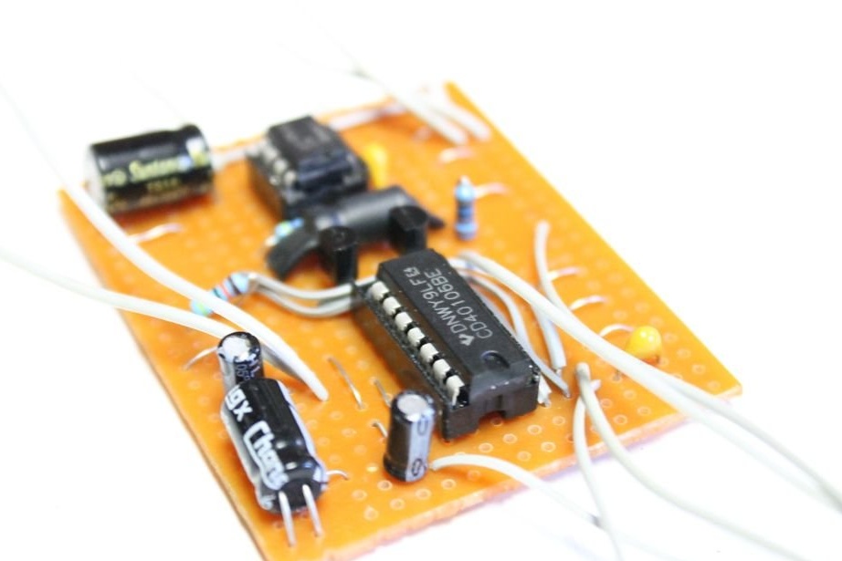
Step One: Scheme
The master himself did not develop the scheme, but took it with of this site. It's small electronic A circuit that makes classic blaster-style sounds. The scheme uses simple parts, it is easy to assemble and has great potential for molding. It has a built-in amplifier chip and speaker, so there is no need for external amplification.
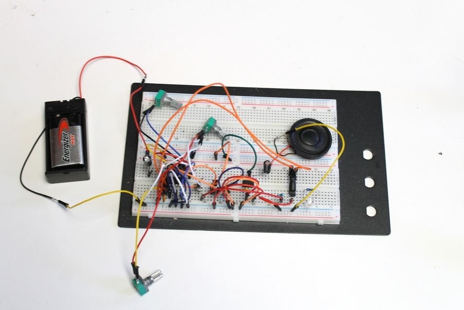
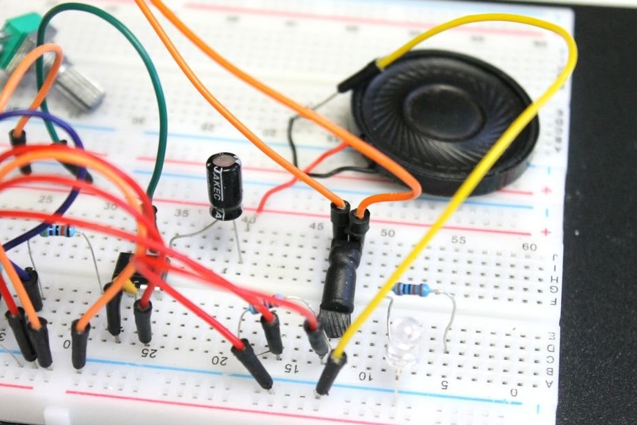
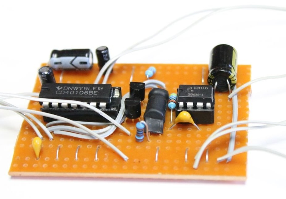
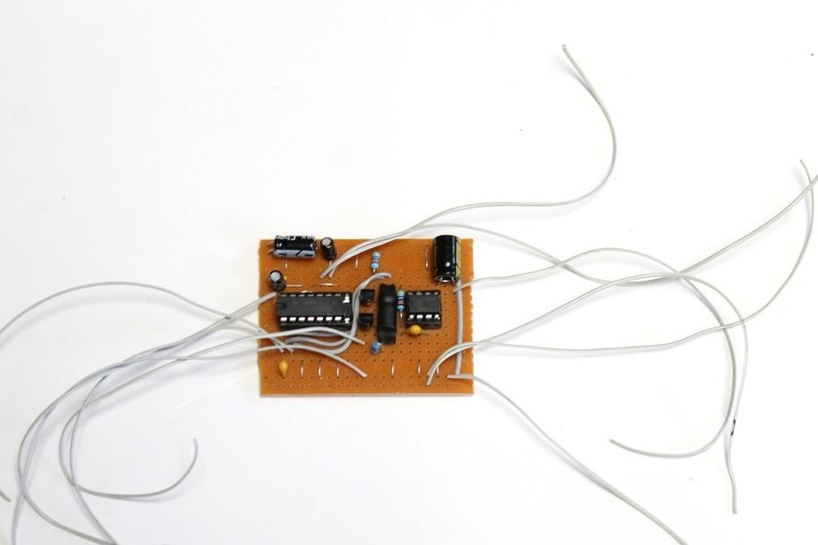
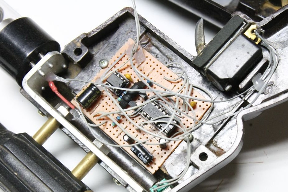
First, the master made the installation on the breadboard, and then, after checking, soldered.
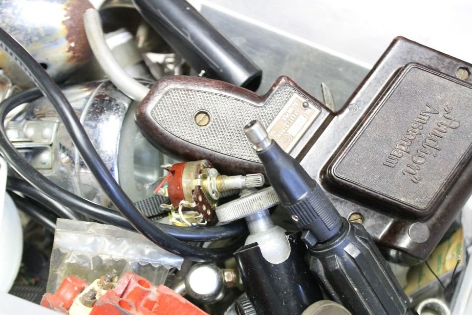
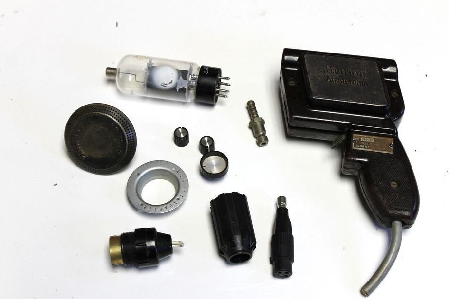
Step Two: Material Selection
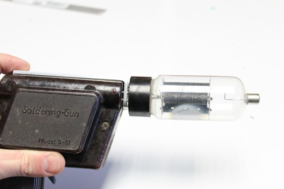
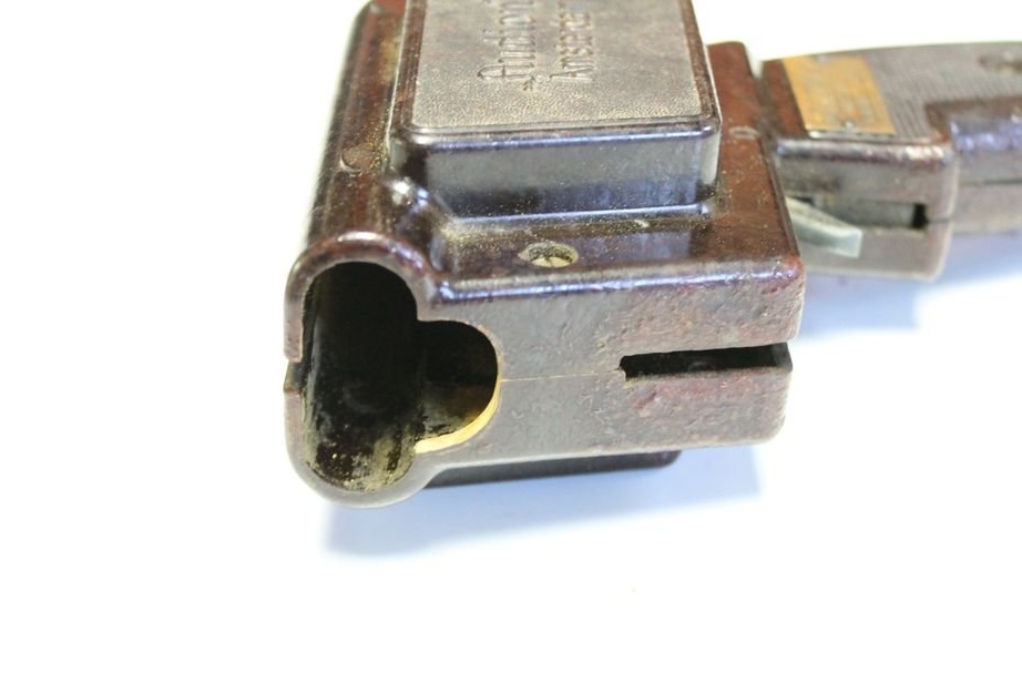
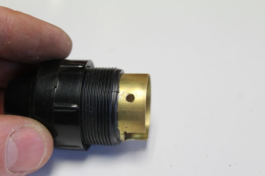
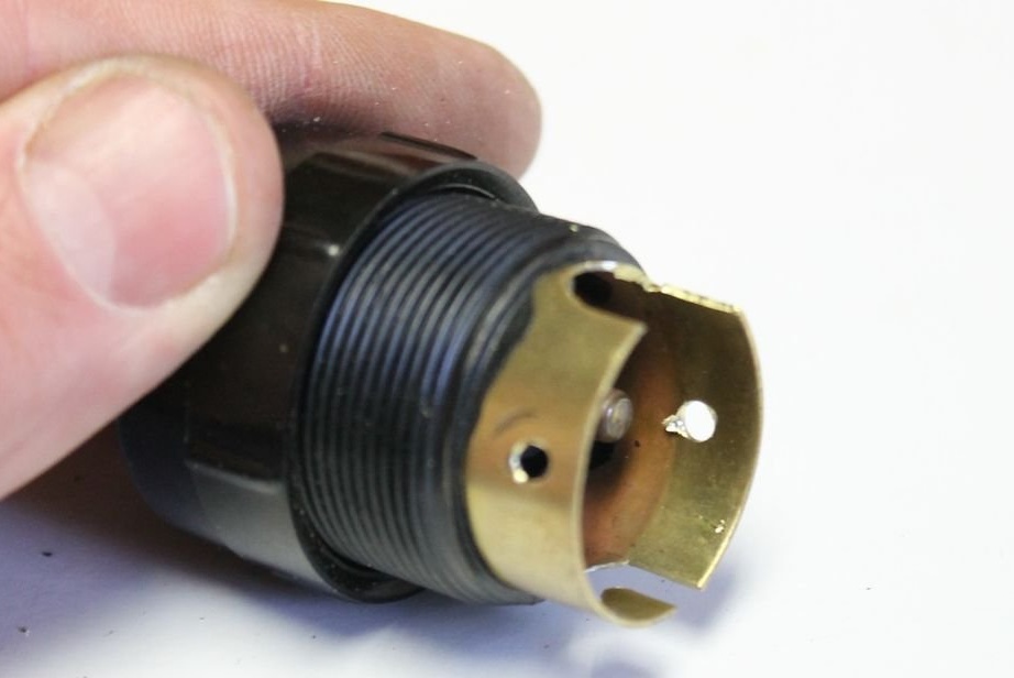
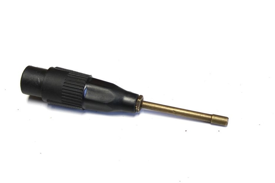
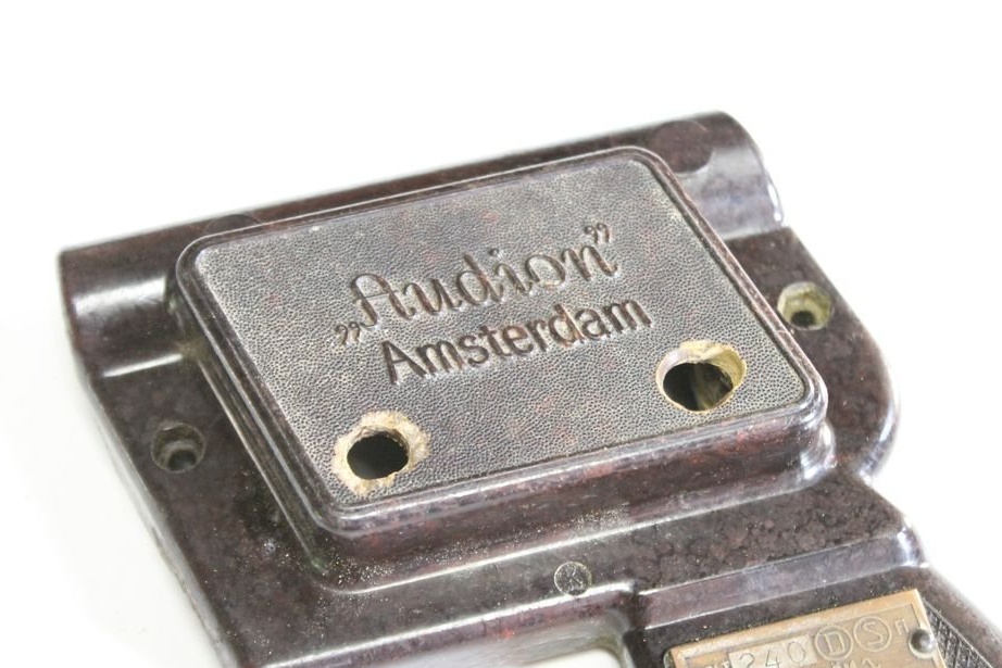
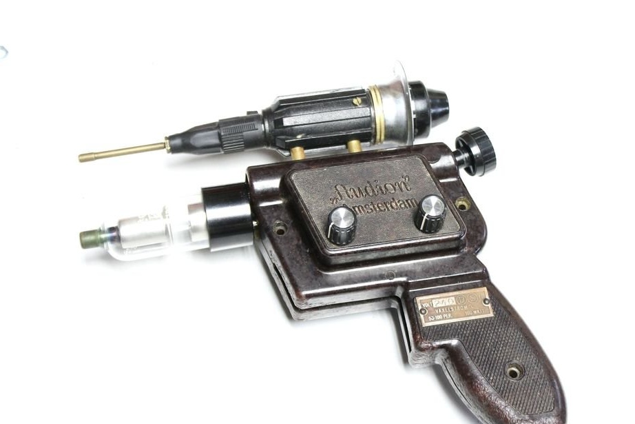
As a case for a blaster, the master uses a case from an old soldering iron. The remaining parts were selected taking into account the case and the board.

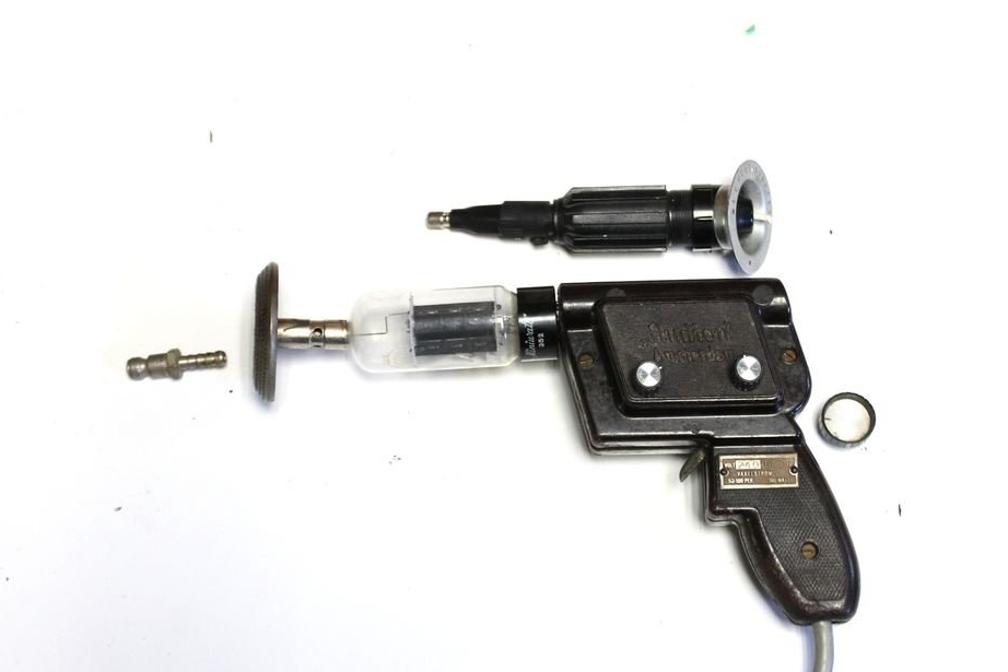
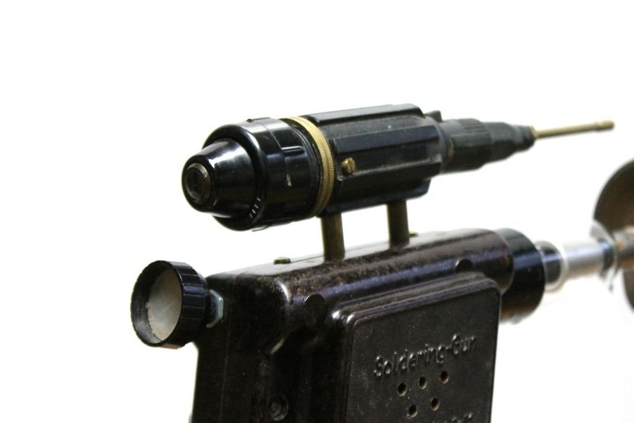
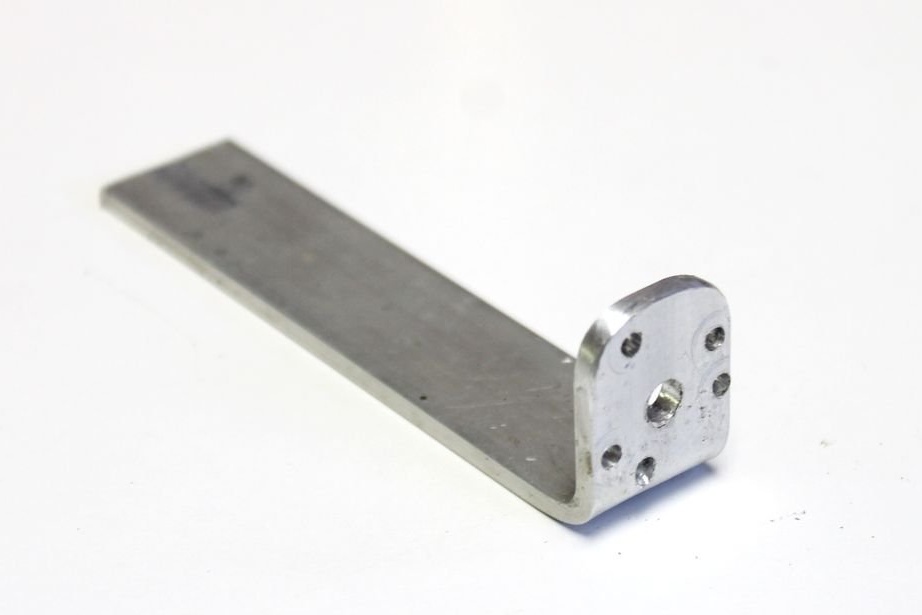
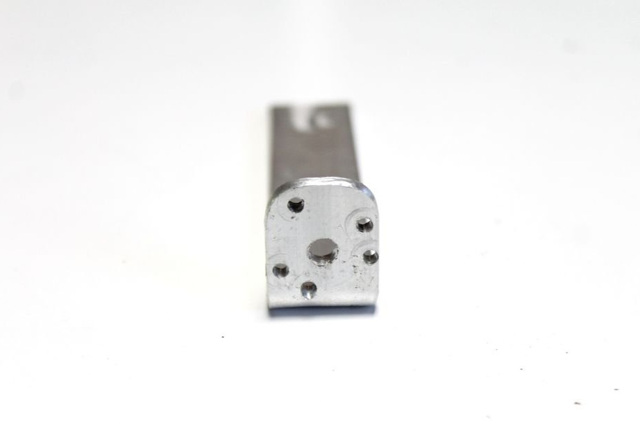
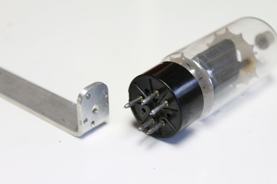
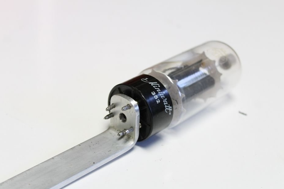
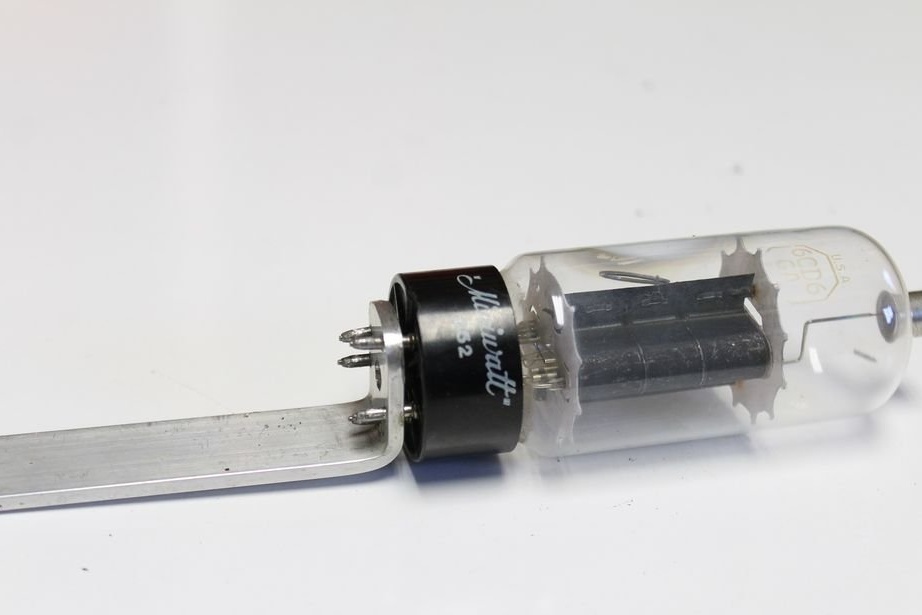
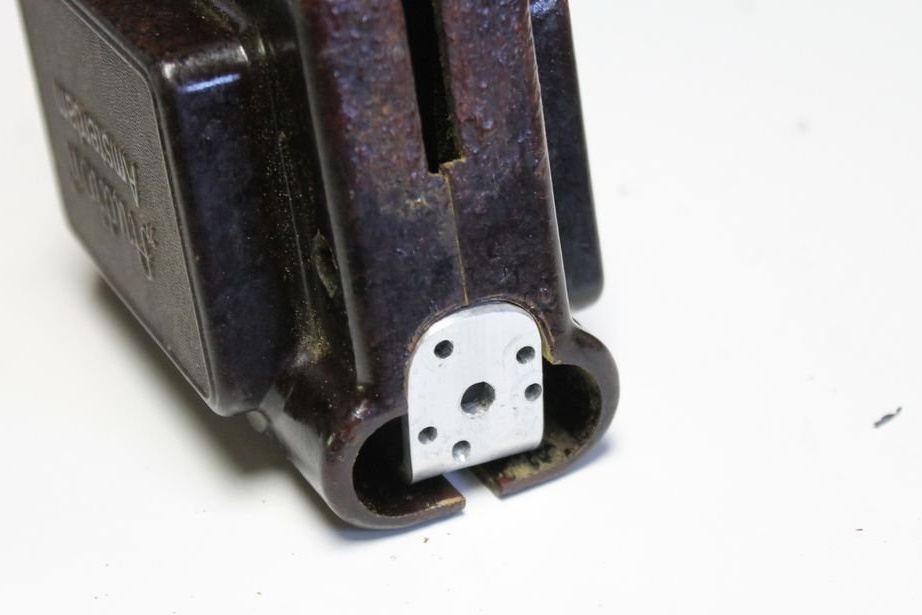
Step Three: Bracket for attaching the radio tube
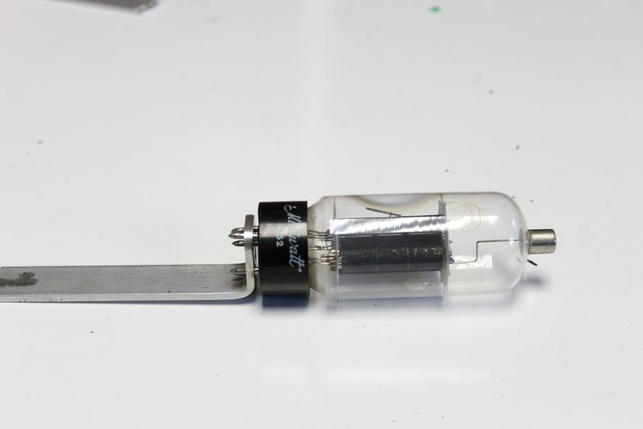
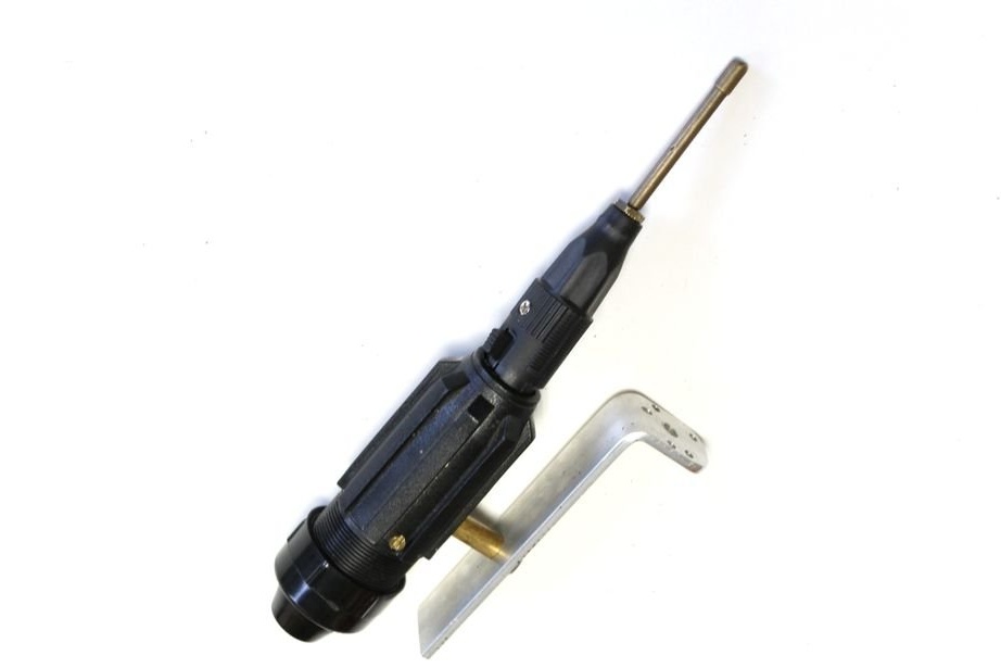
To attach the vacuum tube to the front of the soldering iron, the master decided to make a bracket of aluminum strips. First, he bent one end of the aluminum strip and rounded the edges. Then he marked on the plate the position of the legs of the radio tube. I drilled holes and installed the lamp in the socket. If the lamp does not sit rigidly, then you can stick the legs.
Further, the master cut the case under the bracket.
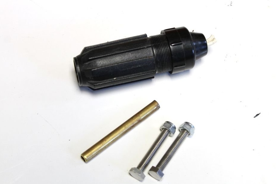
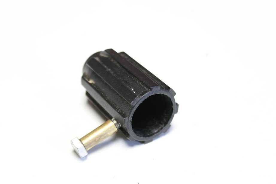
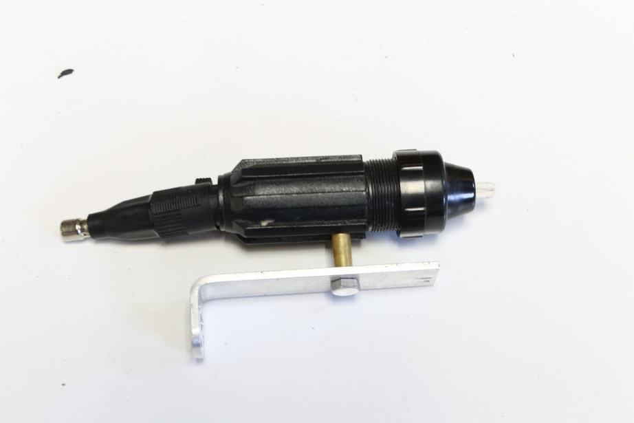
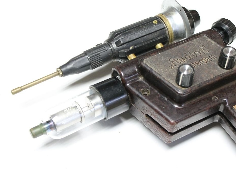
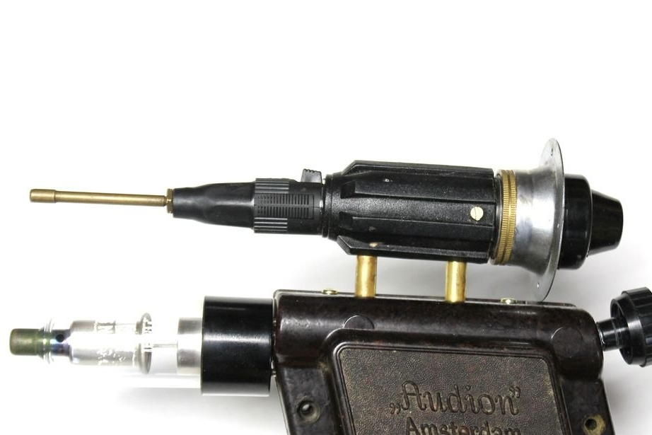
Step Four: Sight
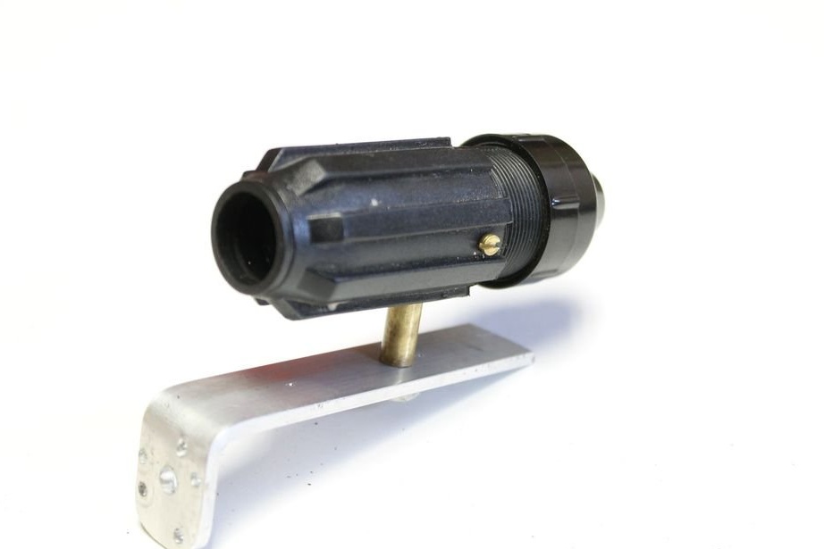
The sight is attached to the aluminum bracket on which the radio tube is mounted. Bolts are closed with copper tubes. The plug from the microphone with a copper tube sticks to the sight.

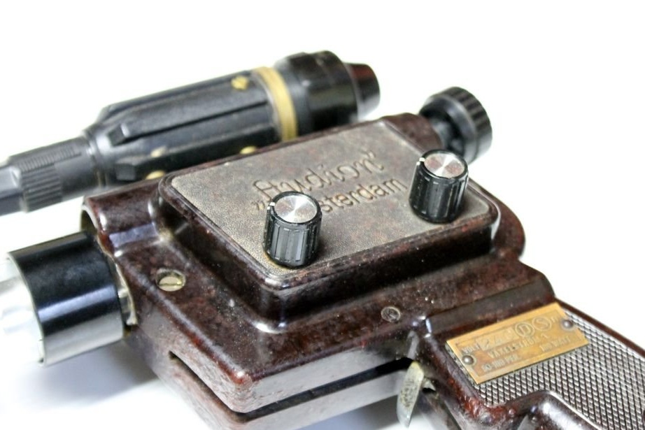
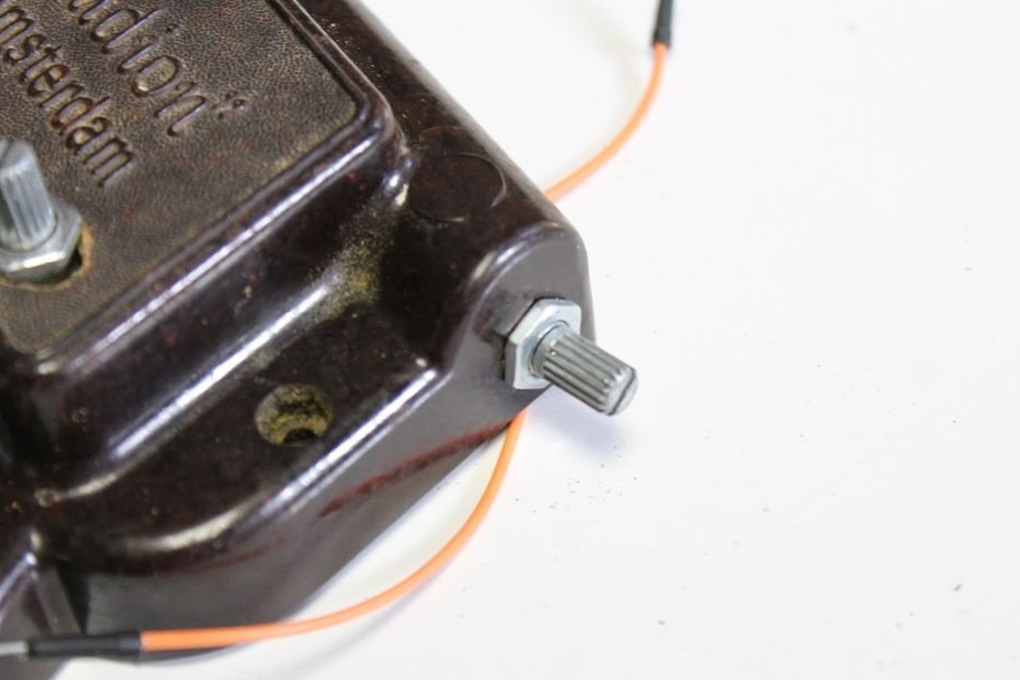
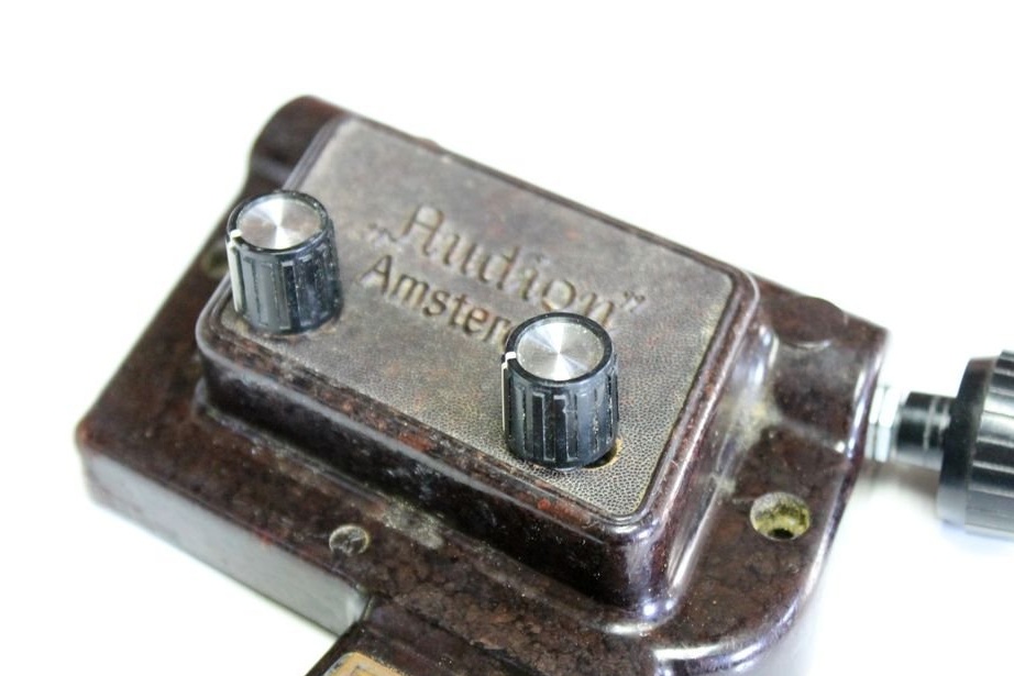
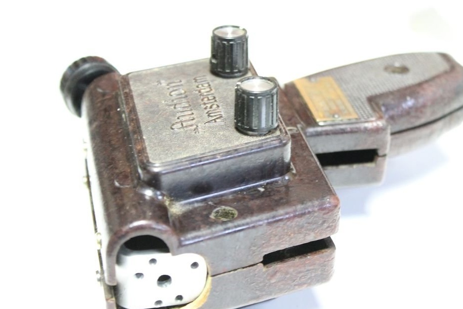
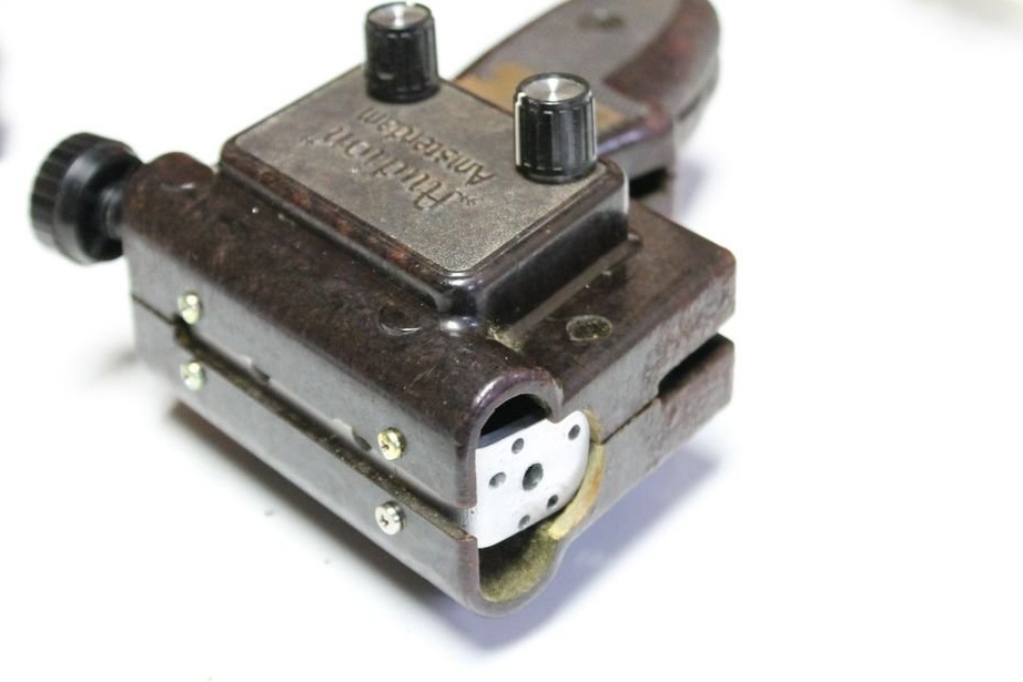
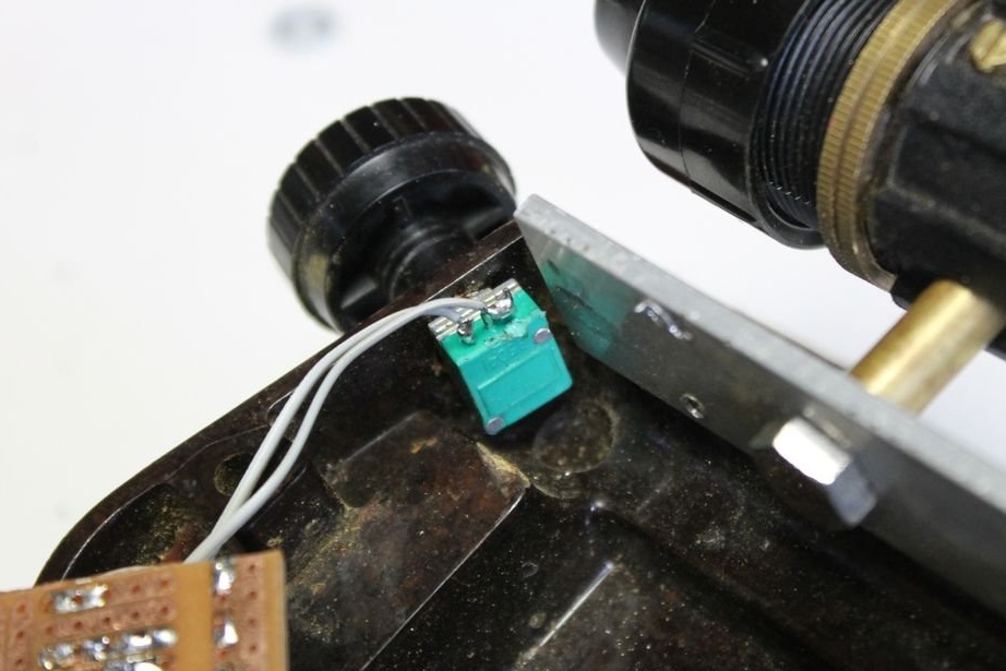
Step Five: Potentiometers
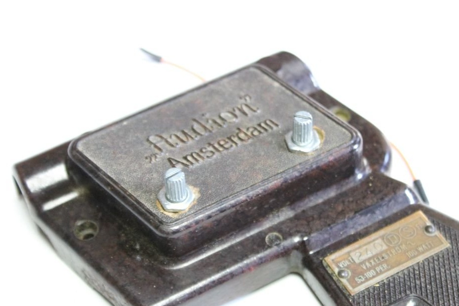
After fitting the parts, the master dismantled the bakelite case of the soldering iron.
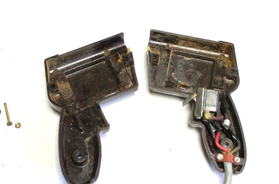
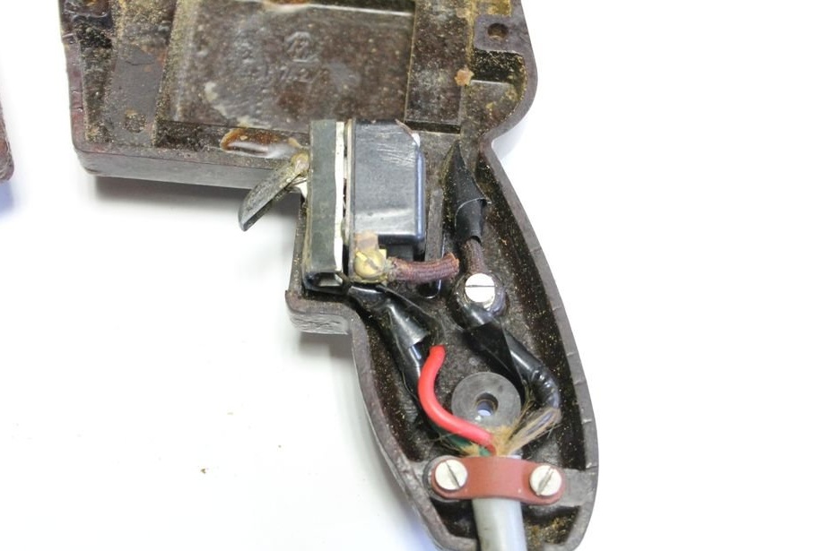
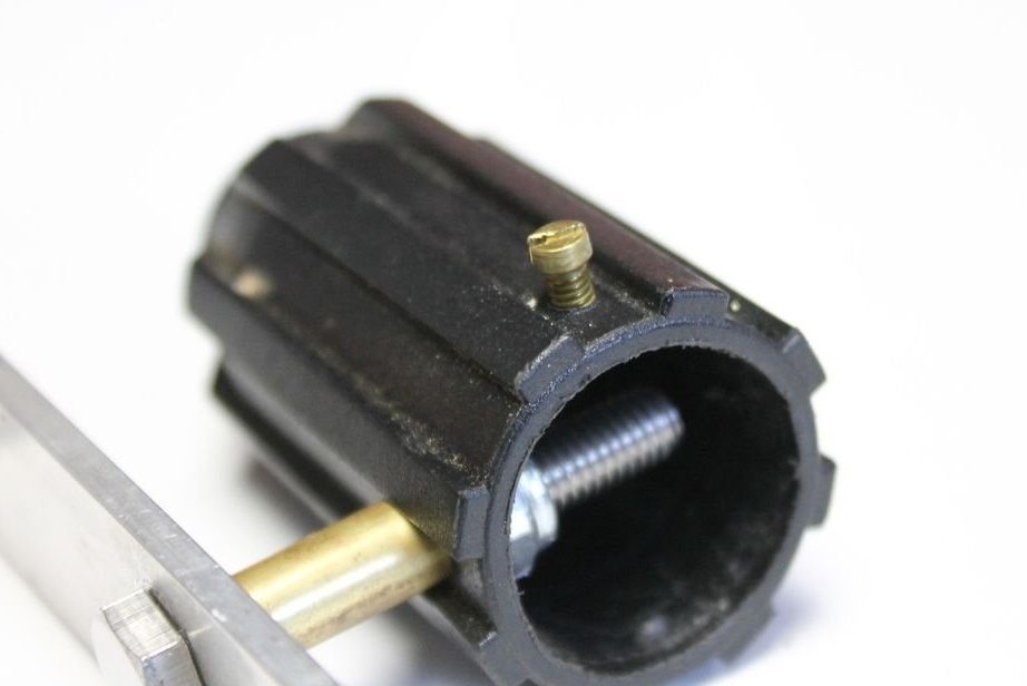
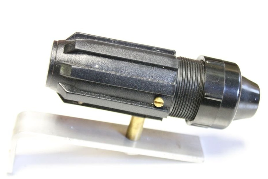
Drilled three holes. One on the back of the case, two on the side. Installed potentiometers.
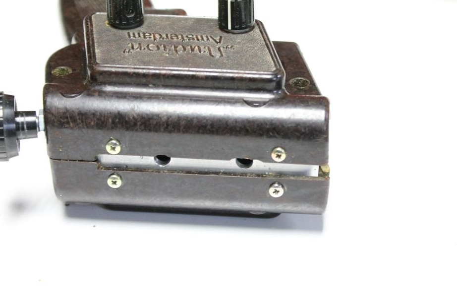
Step Six: Install the Bracket
To fix the bracket, the master drilled holes in it and in the housing. After installing the bracket and fitting the holes, the master divided the case into two parts.
Mounted the sight on the bracket. Unlike the original plan, on two screws.
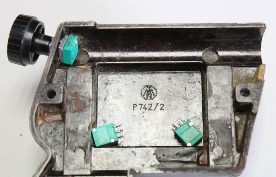
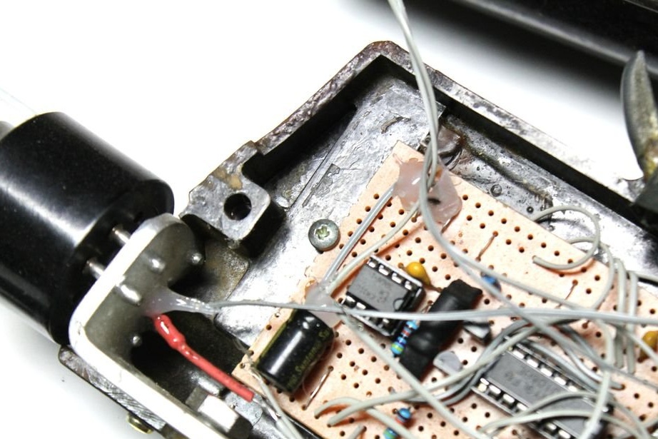
Seventh step: installing the board
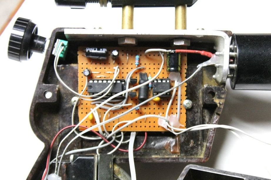
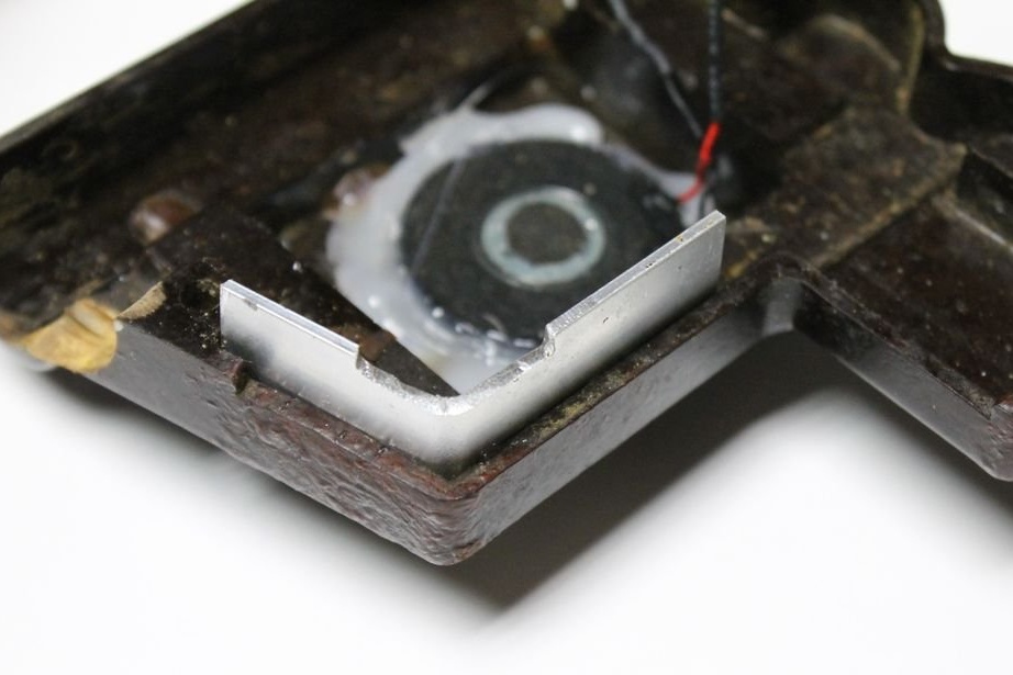
Now you can install the electronics. At the speaker installation site, the master made several holes in the case. The speaker was glued with hot glue.
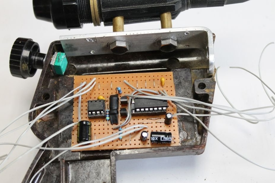
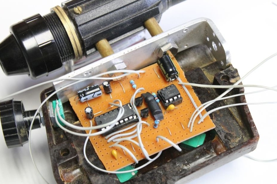
The board was fixed with two screws.
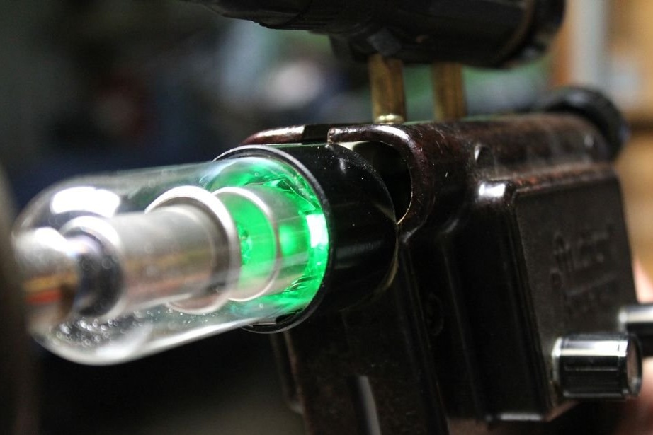
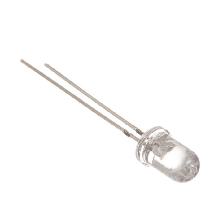
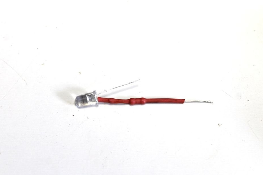
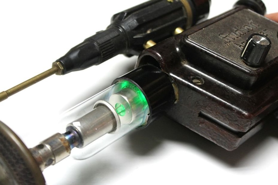
Step Eight: LED
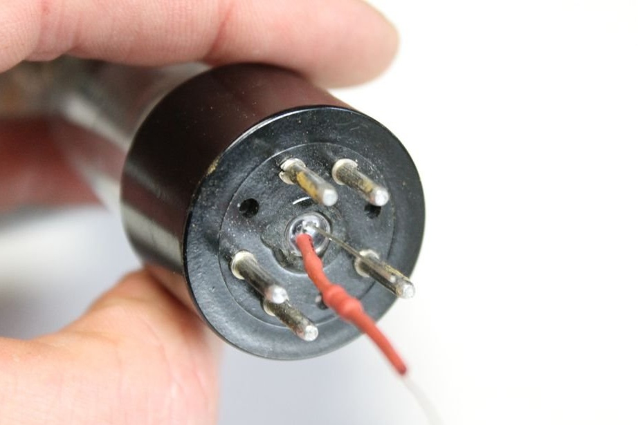
In the radio tube, the master decided to install a green LED. The lamp has a central plastic section that had to be removed. Behind the plastic is glass, which must be carefully broken.
Now you can install the LED inside. This will not give much lighting, but enough for a good effect. I used superglue to fix the LED.
A 3.3 kΩ resistor was soldered to the positive leg of the LED and connected to the board so that it turned on together with the sound.
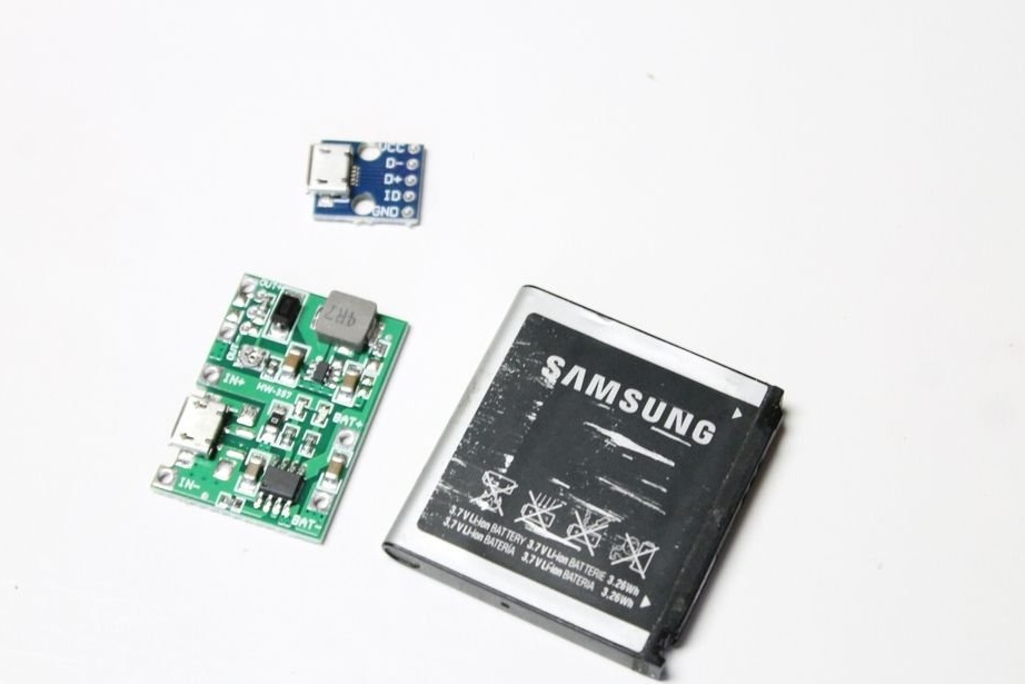
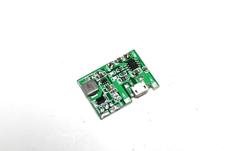
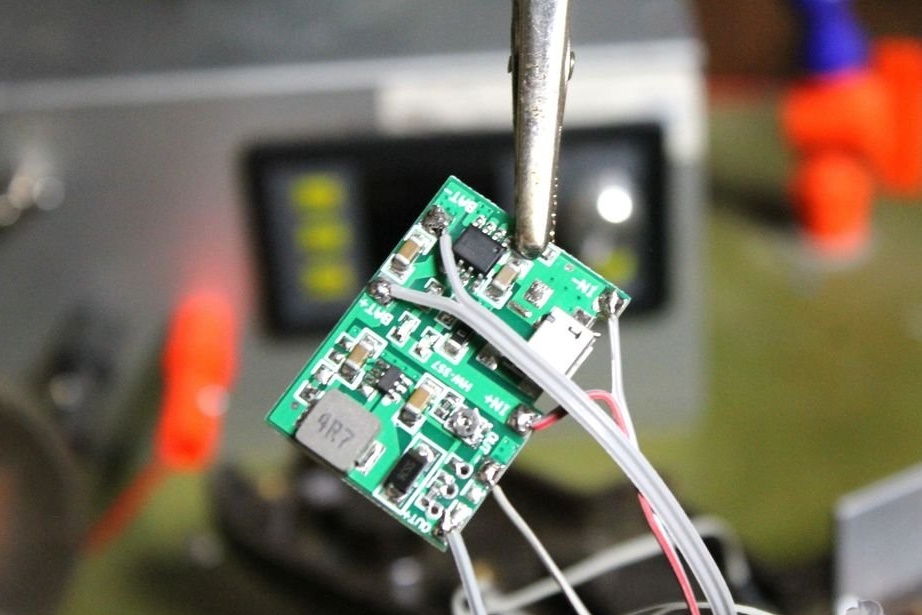
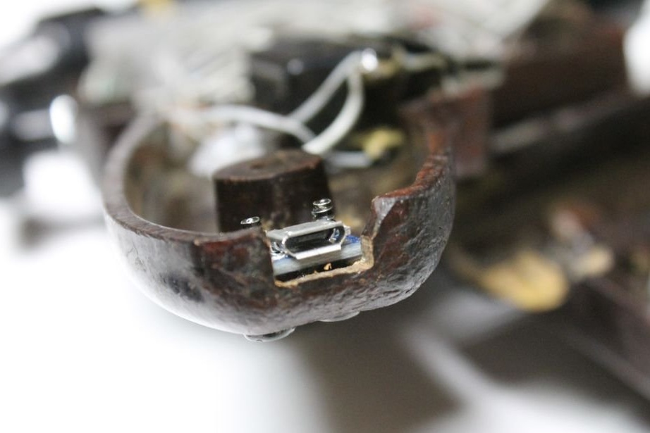
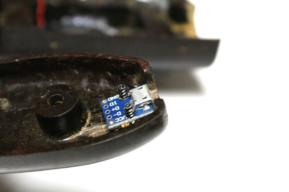
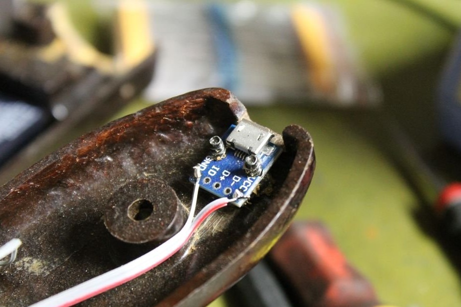
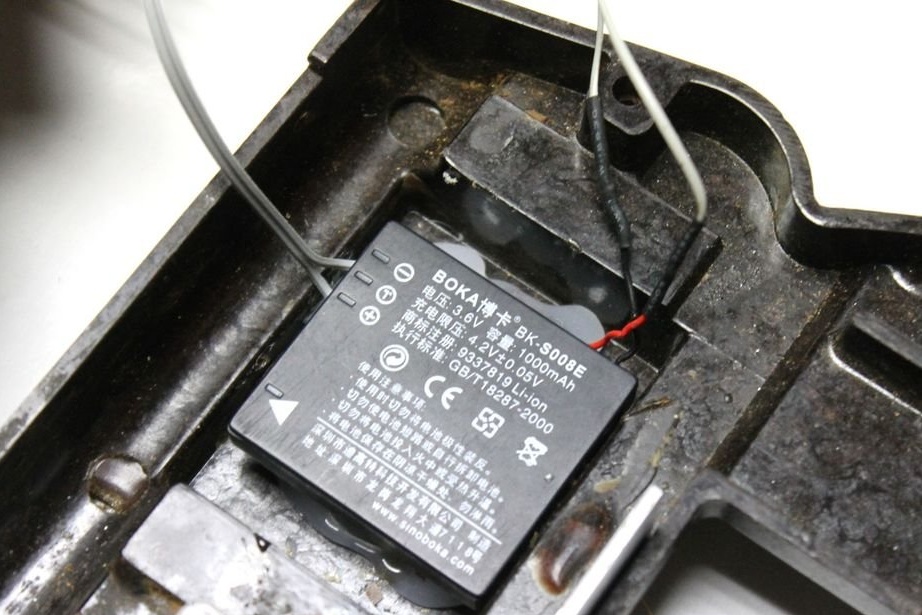
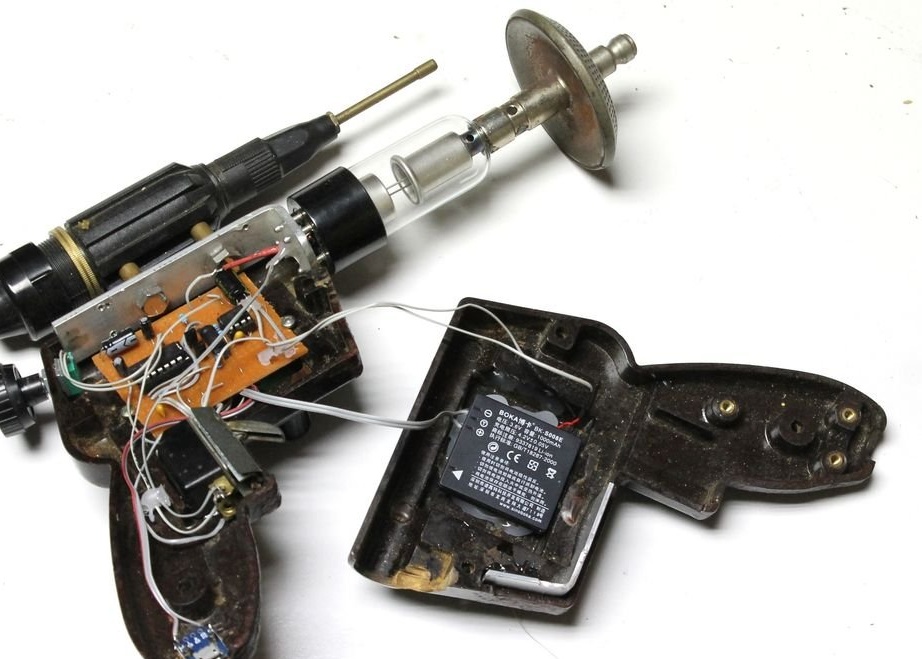
Step Nine: Nutrition
Now that the circuit board was connected, the wizard began to think about how to power and charge the battery. For this purpose, he decided to use a charging module with a voltage regulator. It uses a lithium battery from the phone for power.
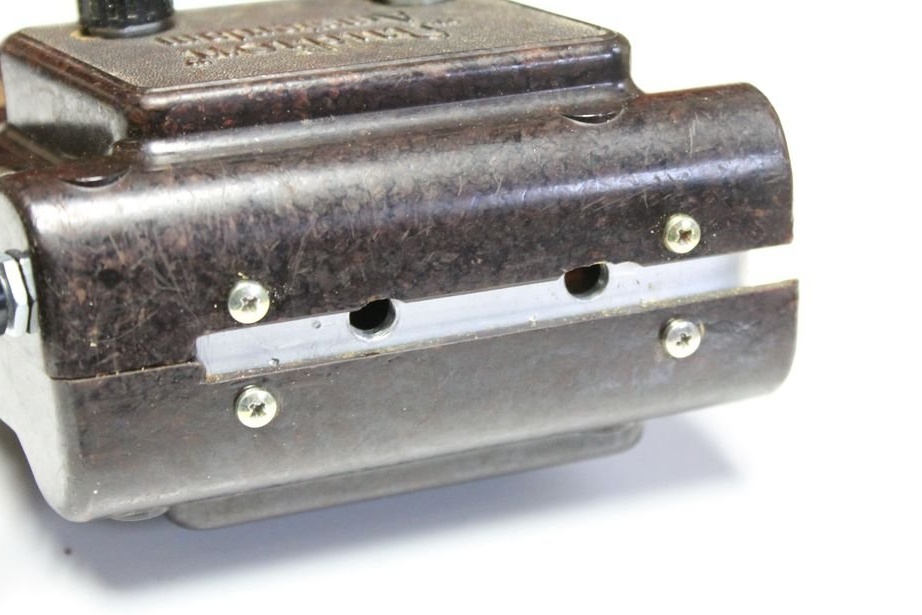
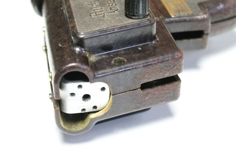
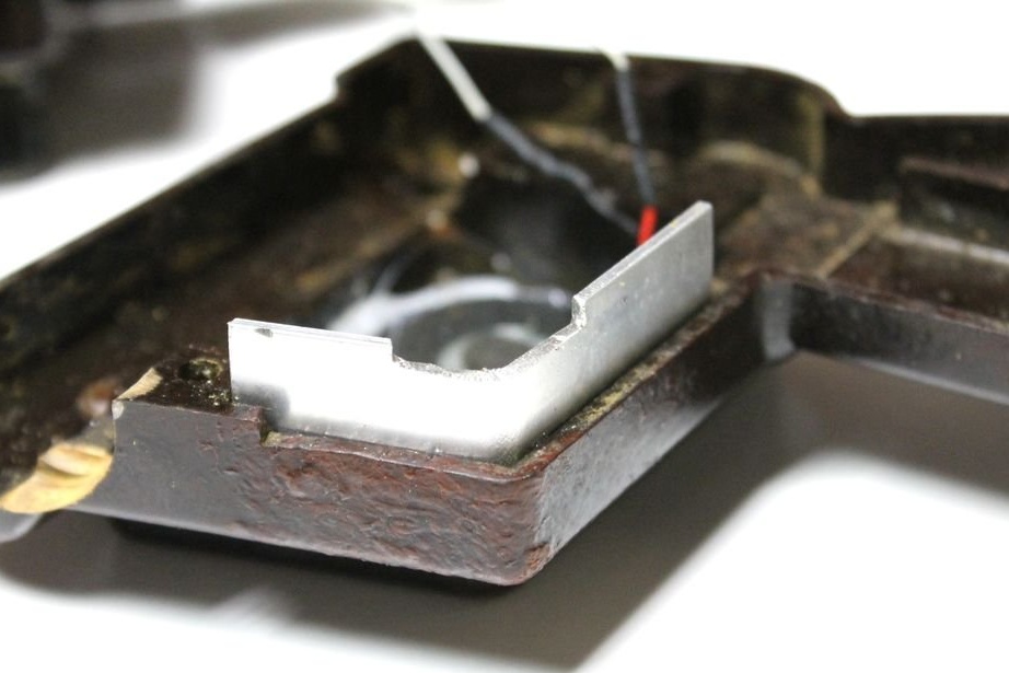
Step Ten: Slots
In the soldering iron case there were a couple of slots through which the insides were visible. The slot at the top closed the bracket. For the lower part, the master bent and secured an aluminum plate.
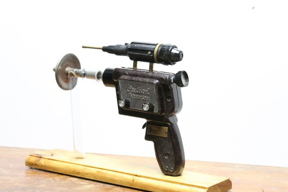
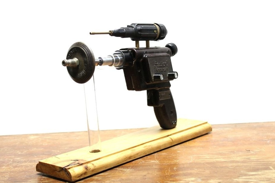
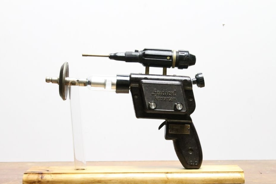
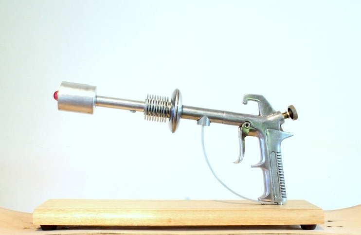
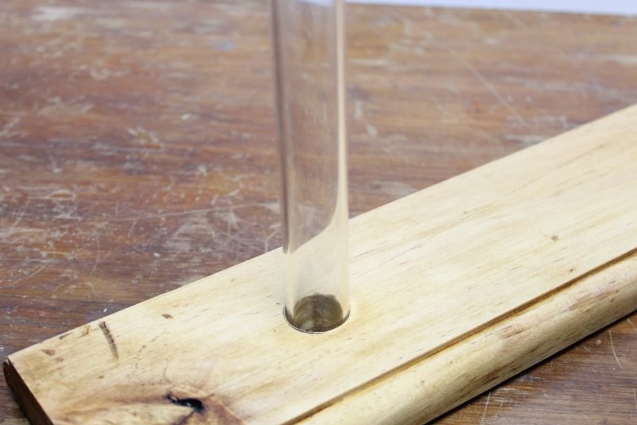
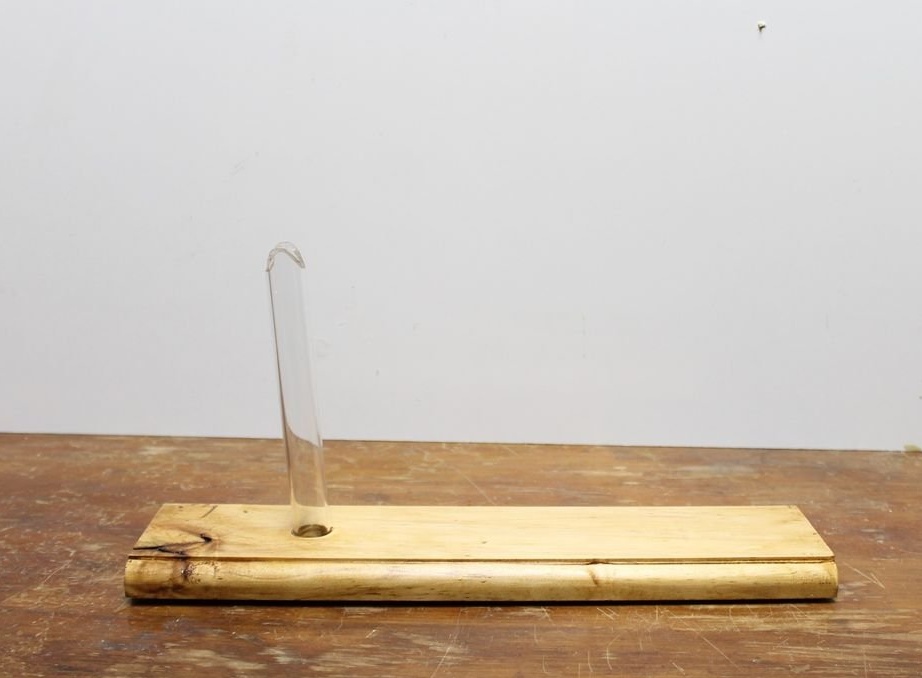
Step Eleven: Stand
Now you can fully assemble the blaster.
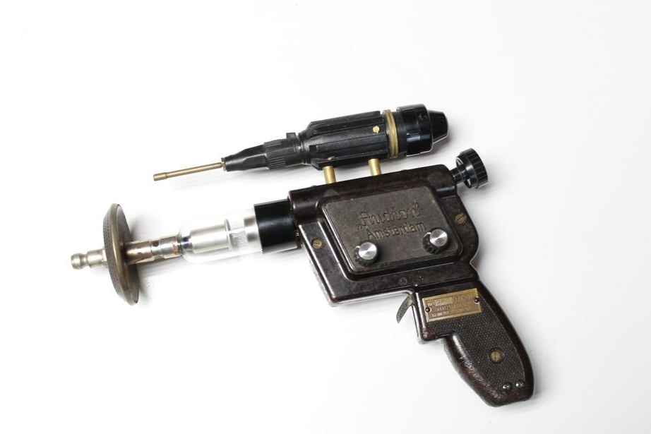
But it’s wrong if he just rolls around, and the master makes, from a board and an acrylic tube, a stand. The master lacquers the board.
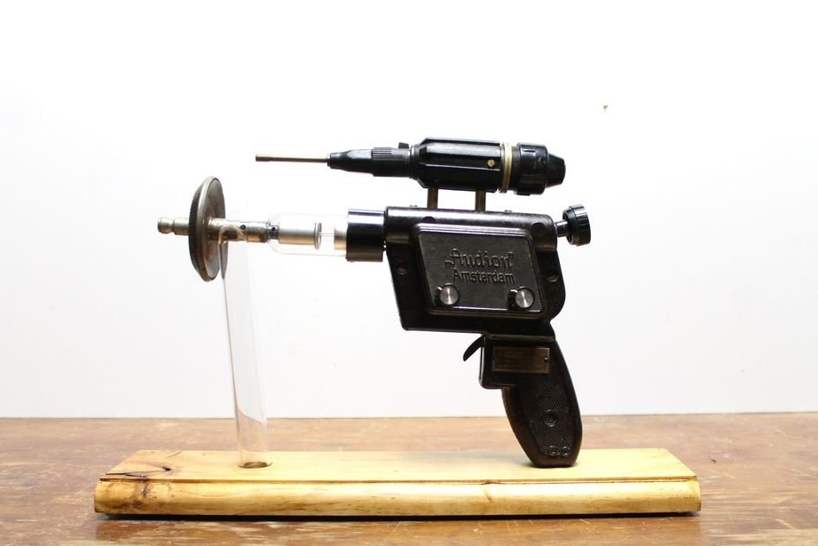
All is ready. Below you can watch a video with an example of the device and all the steps for its manufacture.