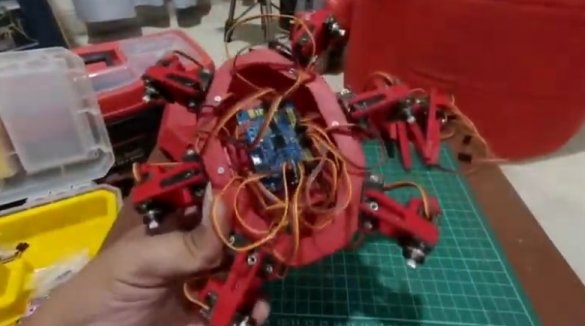
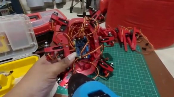
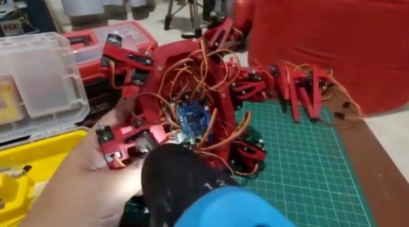
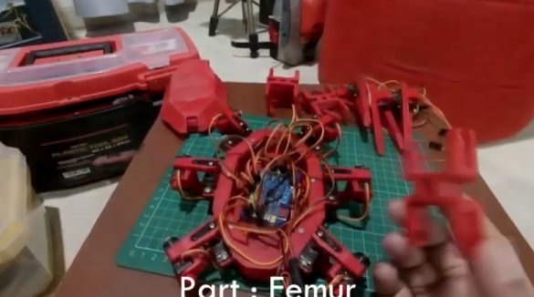
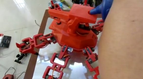
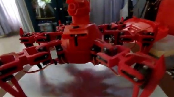
Want to have a fight between spider robots? Then carefully study this article, in it the Master will tell you how to make such a spider. And for clarity of his work, let's see the video.
Tools and materials:
For the spider
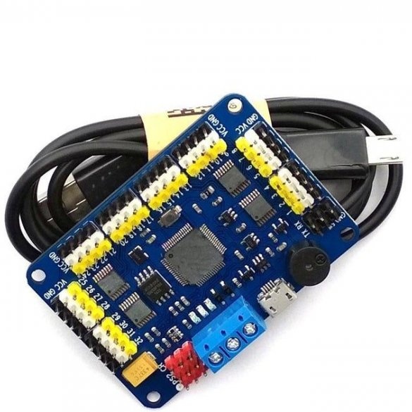
32-channel servo controller;
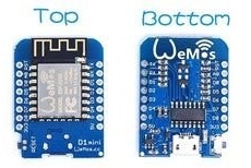
-Wemos D1 Mini controller;
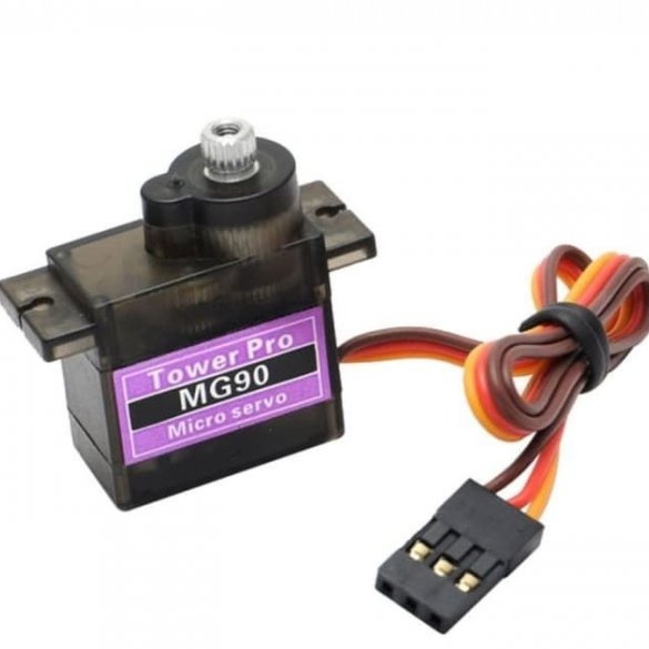
- MG90S Servo Drives - 18 pcs;
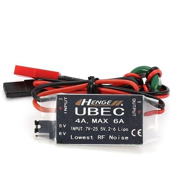
-Ubec 6A 5V controller;
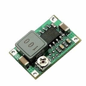
- DC-DC buck converter;
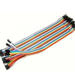
- Jumpers;
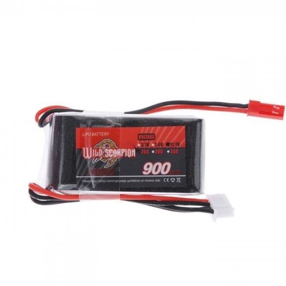
-Battery;
For the tower
-Two engines;
-Power module;
- Lowering converter;
-Servo;
-3D printer;
-Glue gun;
-Glue;
-Screwdriver;
-Fasteners;
-Double sided tape;
-Nippers;
-Knife;
-Nadfiles;
-Plastic balls;
-Soldering accessories;
Step One: Printing Parts
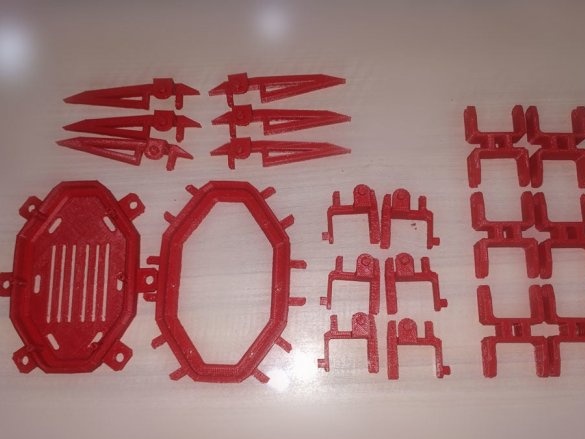
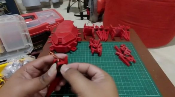
First you need to print the details of the body and legs on a 3D printer. You can download files for printing on this the link.
Step Two: Build
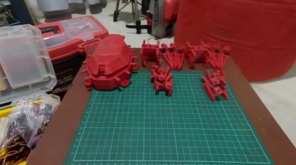
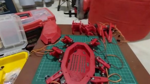
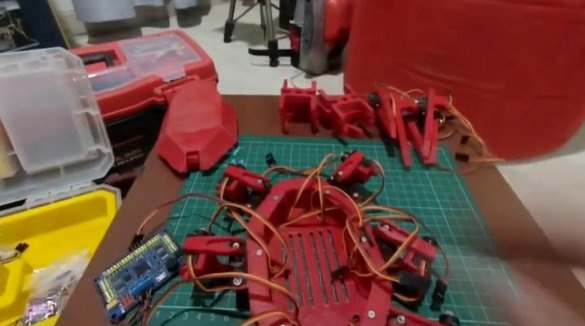
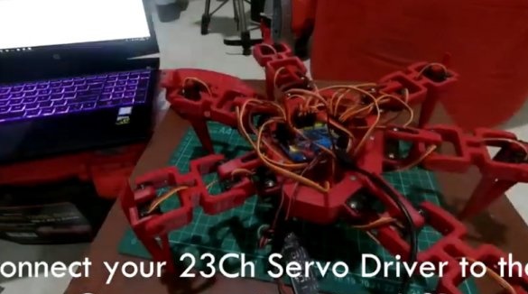
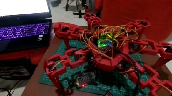
Now you need to collect robopauk.
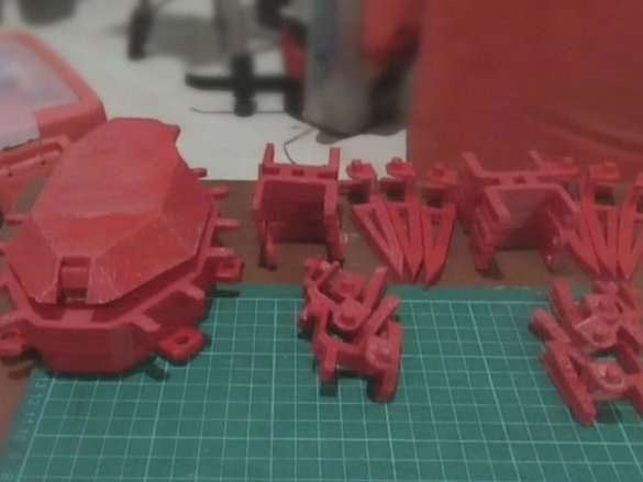
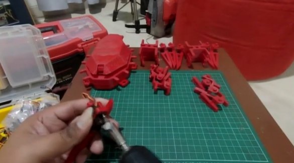
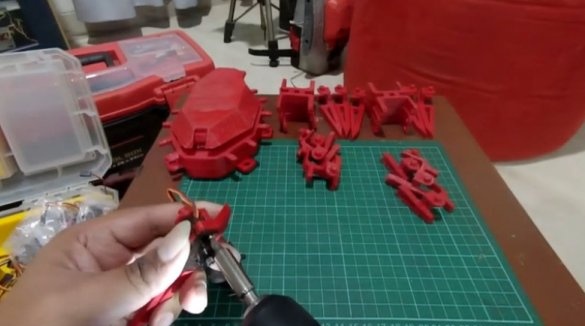
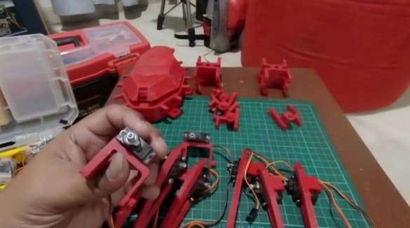
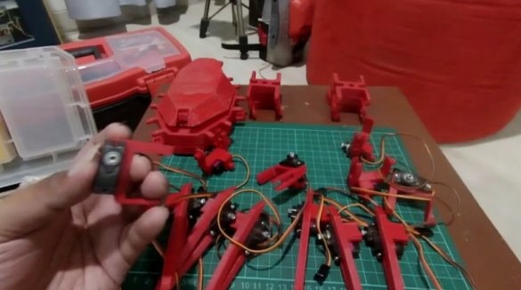
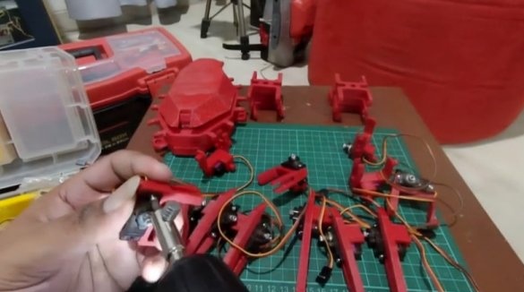
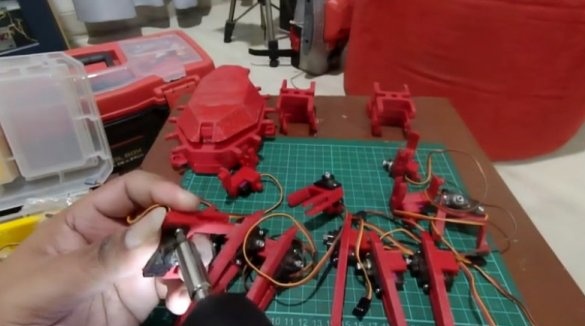
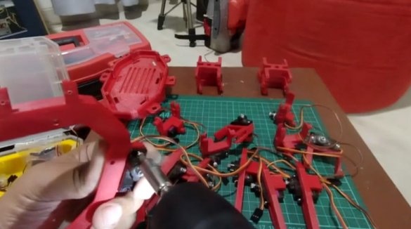
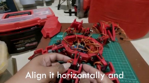
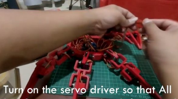
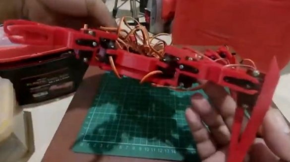
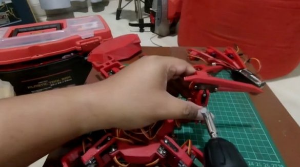
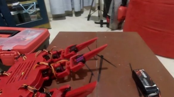
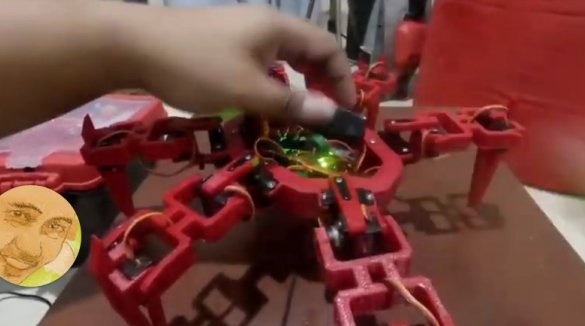
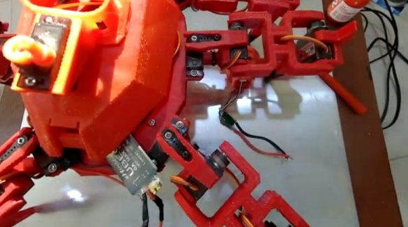
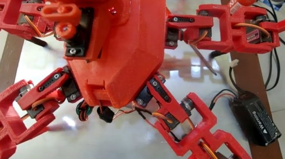
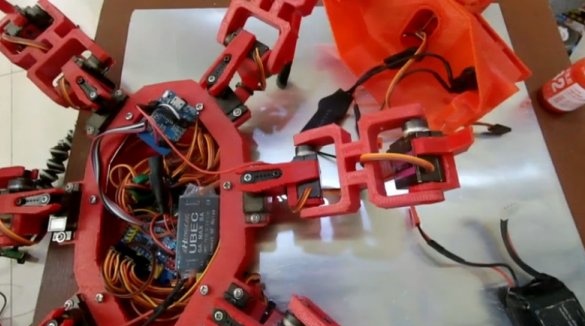
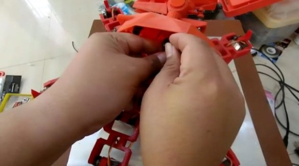
The master installs servos on the joints of the spider's legs. In total, the robot has six legs and three servos on each leg.
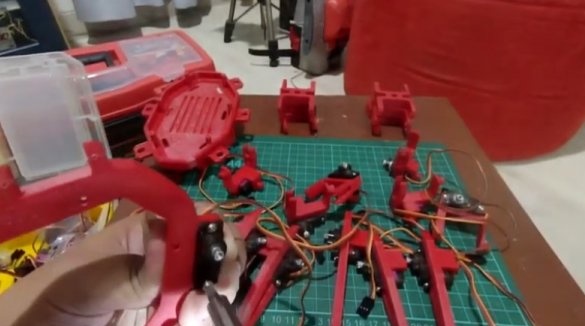
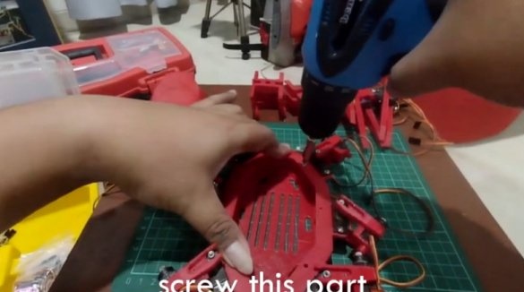
Installs servos on the chassis platform.
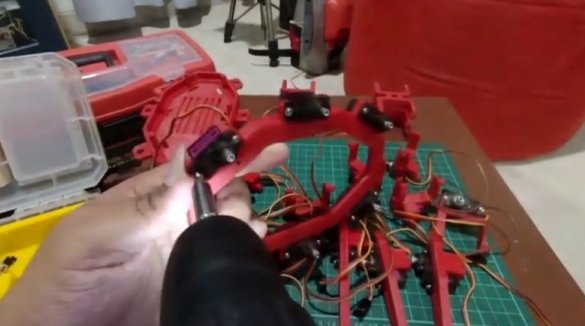
Fastens the first joints of the legs to the platform servos.
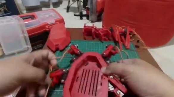
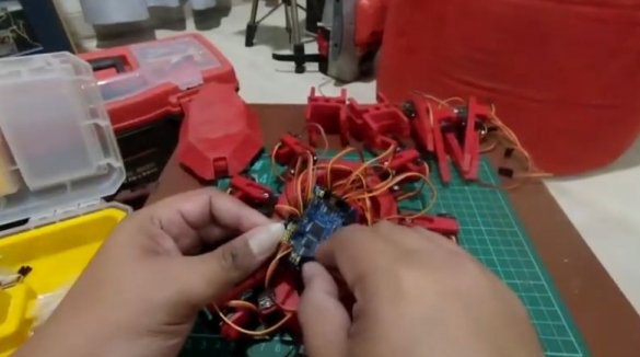
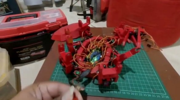
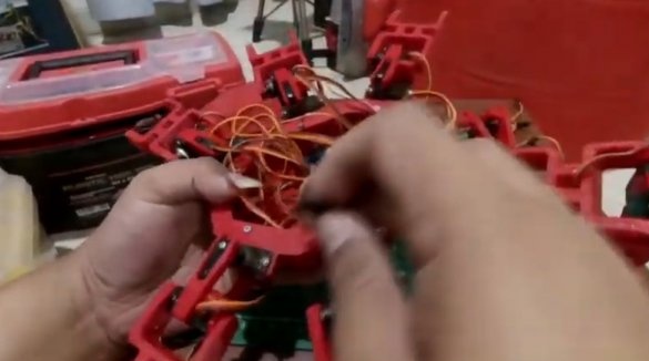
The wires are pulled into the technological holes and connected to the controller.
Installs stubs.
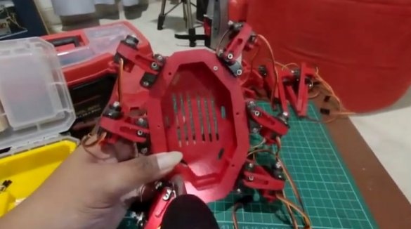
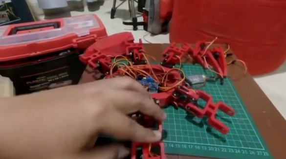
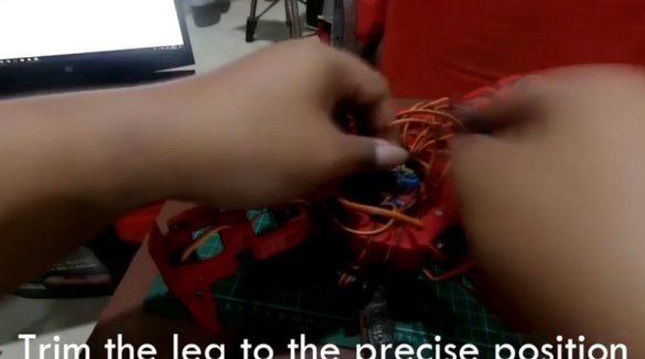
Establishes the second joints of the legs. Connects wires from servos to the controller.
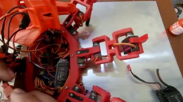
Installs the third joint. With this joint, the spider will abut against the surface when moving.
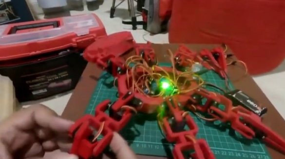
Connects and checks the operation of each servo drive.
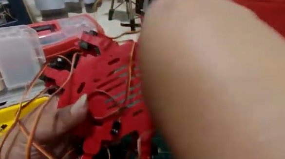
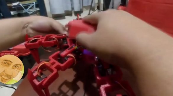
If everything normally fixes the wires with ties, installs the battery and closes the cover.
The build process can be seen in the video.
Step Three: About electronics
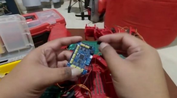
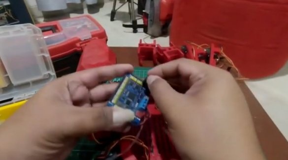
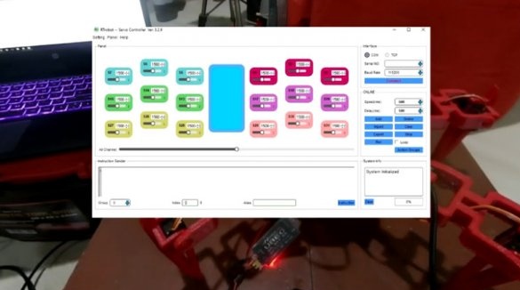
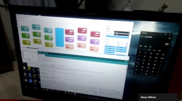
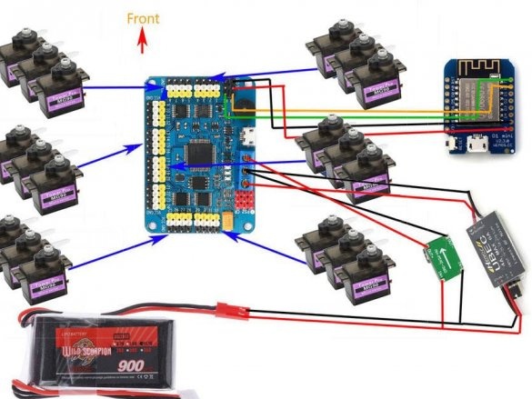
The wizard used the RTrobot servo controller to control the movements. Management program can be downloaded here or here.
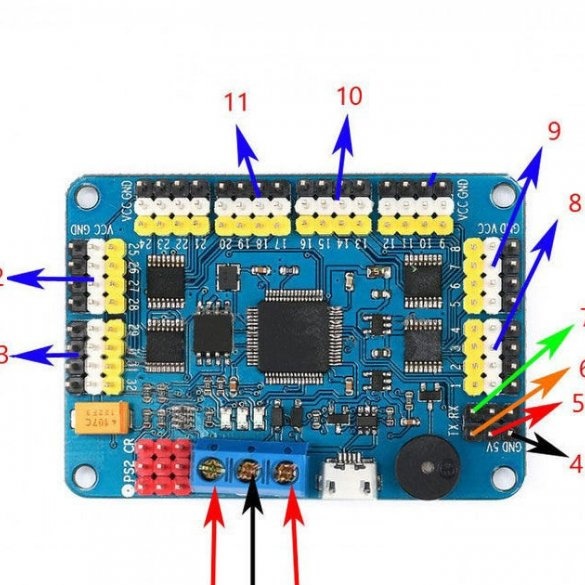
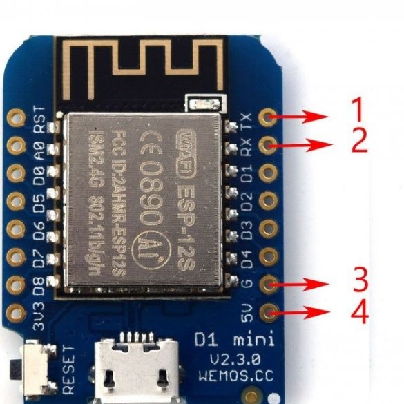
Everything is connected as follows:
1. 5V (+) UBEC output
2. Earth from UBEC and buck converter
3. 5 V power supply (+) from the converter
4.on the Wemos D1 mini G pin
5. to Wemos 5v
6. to Wemos D1 RX
7. Wemos TX
Servo drives are connected to pins 8 through 13.
Install the code on NodeMCU. You can download it here.
WeMos D1 mini is the minimum ESP8266 Wi-Fi card.
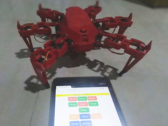
Using wemos D1 mini as a WIFI access point, you can send a serial command to the servo controller. All that is needed is just to flash the nodeMCU board with code, and you can connect the smartphone to the nodeMCU AP. Then, using a web browser, go to http://192.168.4.1.
Important.
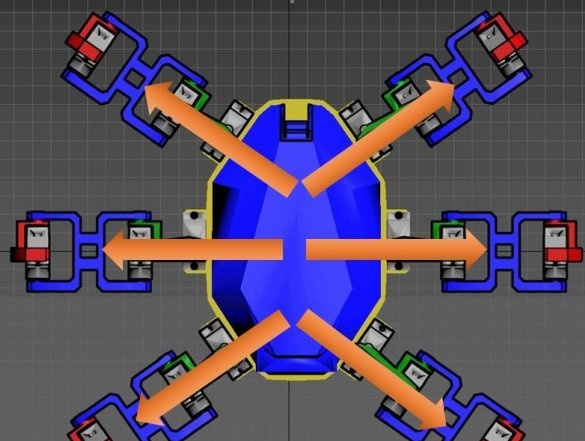
when you turn on the servo, all servos will move to the original / standard position
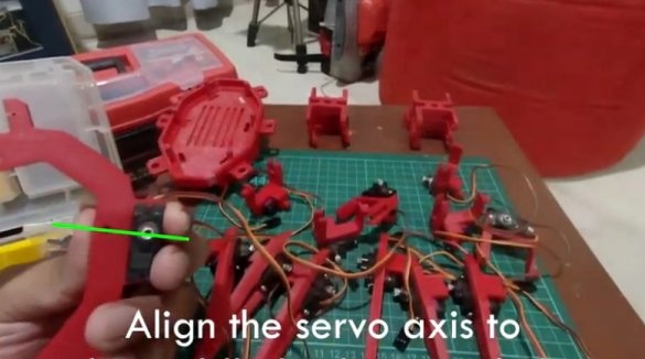
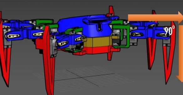
install the servos as accurately as possible, as shown in the figure above or in the video
adjust the position of the joints, turn the device off and on again to make sure that all legs are in the correct position
if the joints cling, rub, adjust the position.
Step Four: The Tower
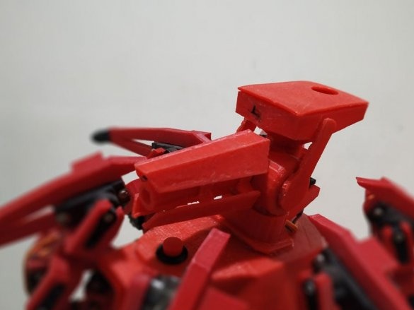
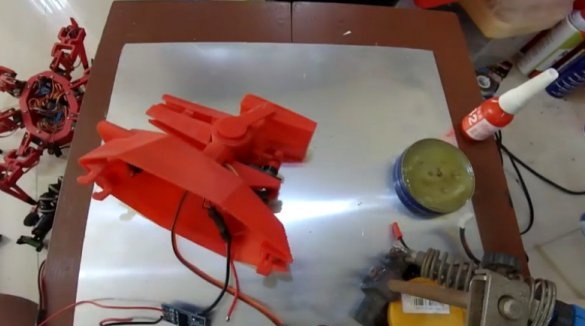
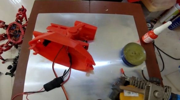
Now we turn to the assembly of the tower.
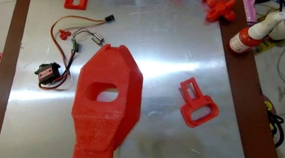
First, the details of the tower need to be printed. You can download files on this the link.
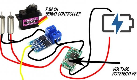
Then the master proceeds to assemble the tower. The circuit for turning the tower and connecting the electrical parts is below.
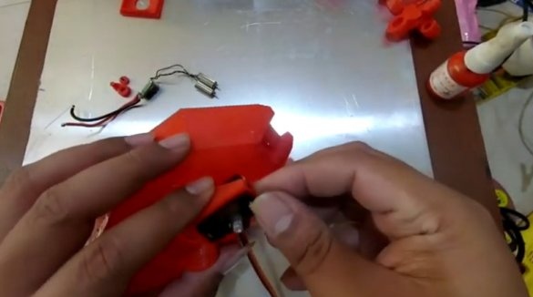
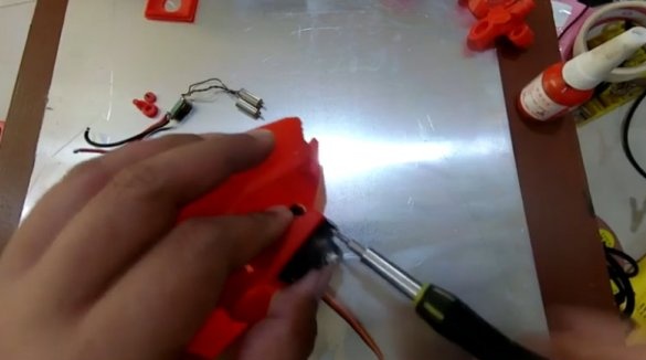
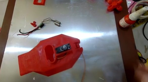
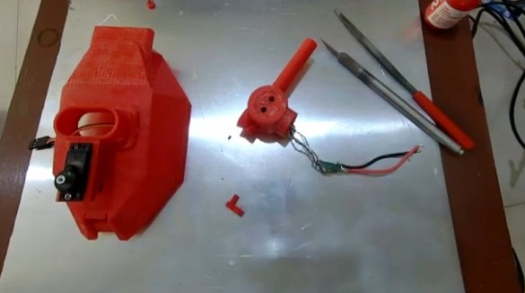
Installs a servo on the tower.
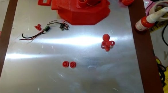
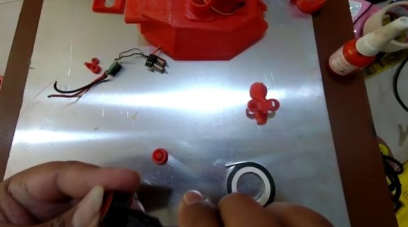
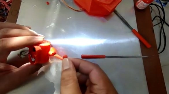
Double-sided tape sticks to the rollers.
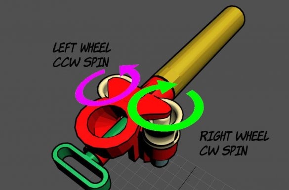
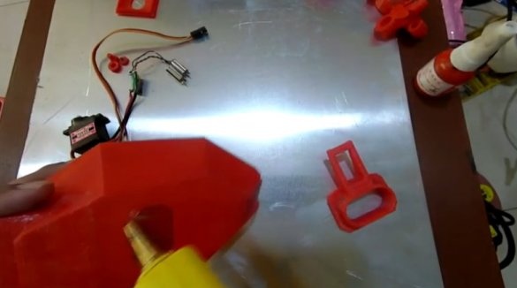
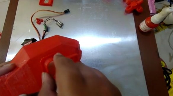
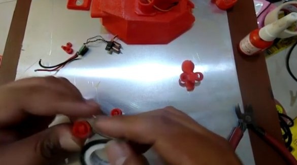
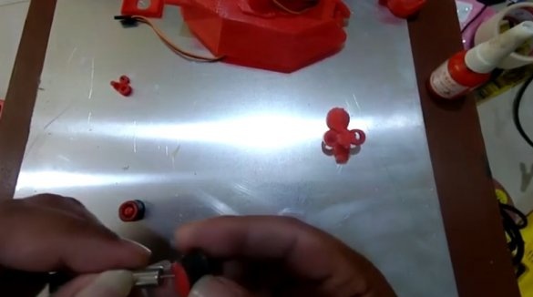
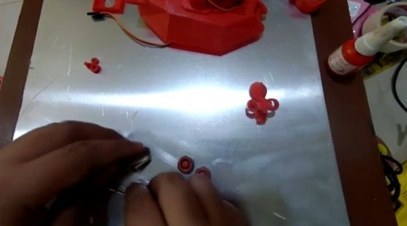
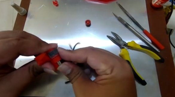
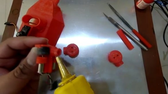
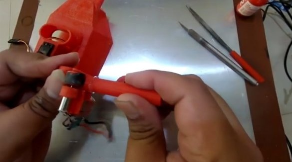
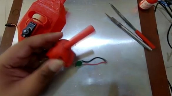
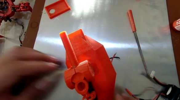
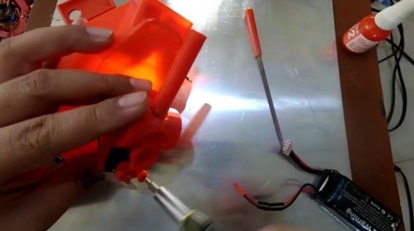
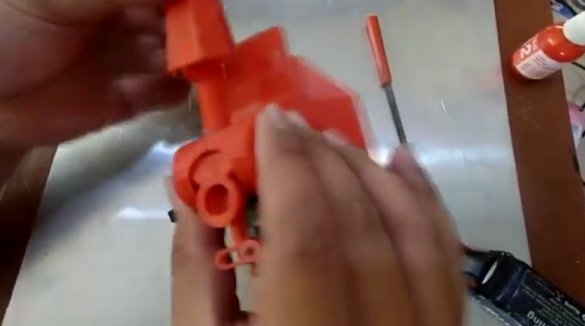
Collects a gun. Installs motors in a holder. Installs rollers on the motor shafts.
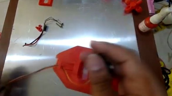
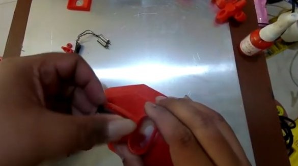
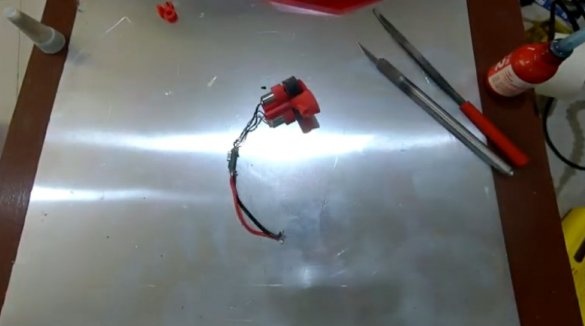
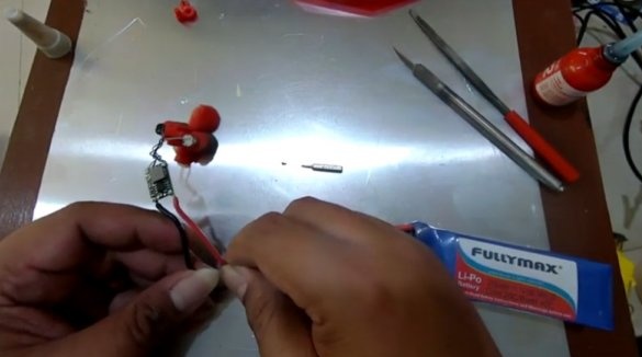
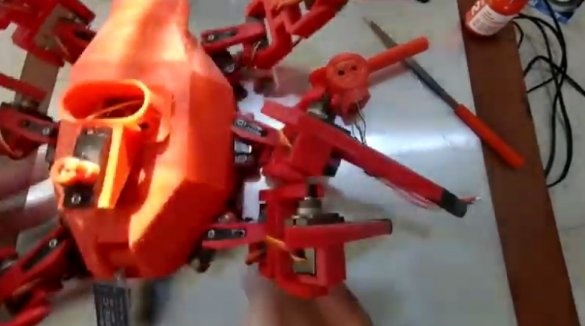
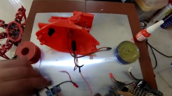
Connects wires and collects the tower.
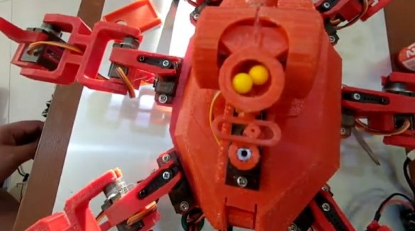
Loads shells and checks the operation of the gun. The mechanism can be adjusted by moving the holder on the servo shaft.
It makes the final connection, assembly and inspection.
Video with the assembly of the tower can be seen below.
All is ready. Gather one more such robopauk and you can arrange fights.

