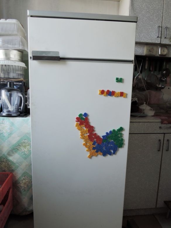
We got an old Biryusa-17 refrigerator. He was many years old ...
The bimetallic thermal switch worked poorly for him (almost did not work). He disconnected and threw it away, and in return set the thermostat according to the hardloca scheme. And there was a light switch (~ 220 V) open type on an incandescent bulb (oh, horror!) 220V.
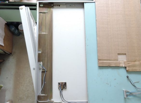
All this was removed (and the place inside was freed). Instead, a 12V LED strip (15 LEDs) was installed (glued). And the contactless switch on the reed switch. The magnet is glued on the door from above, and the reed switch with the control circuit in the visor of the refrigerator.
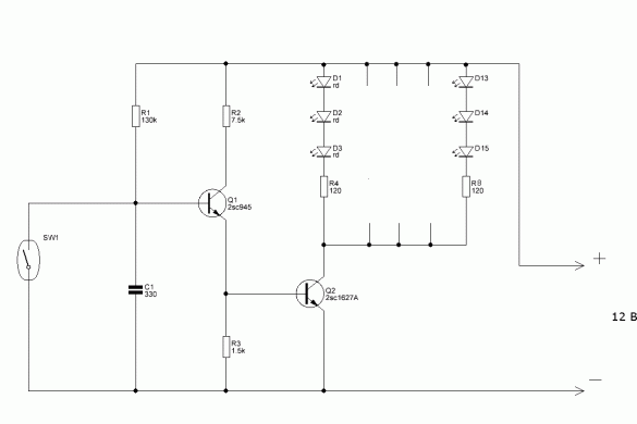
Power supply (12 V) is taken from the thermostat circuit source. If there is no thermostat, you can put a separate source at the bottom of the refrigerator next to a ~ 220 V junction box. The electrical circuit diagram of the device is shown below.
Materials and tools:
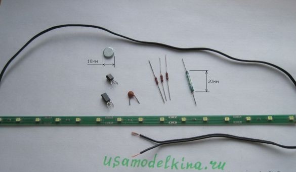
Details for the manufacture are shown in the photo (3)
Magnet D = 10mm (used in boxes from cellular and TP)
3 resistors 0.125 W (ratings are shown in the diagram)
Transistor 2SC1627A
Transistor 2SC945
LED strip (15 LEDs soldered in 5 groups of 3 LEDs) for a voltage of 12 V
330 pF capacitor
Reed switch (20mm)
Insulated wire (~ 2m if two-core)
Universal scarf
Reed soldering scarf (textolite 38x12 mm)
Power Supply 12 V (300 mA)
Soldering iron
Rosin, solder (POS61)
Side cutters
Tweezers
Drill with a drill (optional)
Clay Moment (a bit at all)
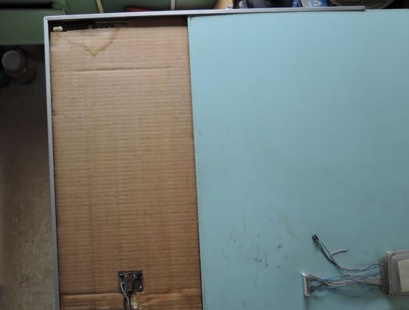
Top mounting view
The control scarf is recessed into the cardboard insulation
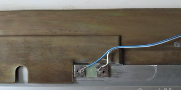
Type of mounting a reed switch on a textolite scarf. The scarf is glued to the refrigerator case (duralumin corner in this case). On the glue moment.
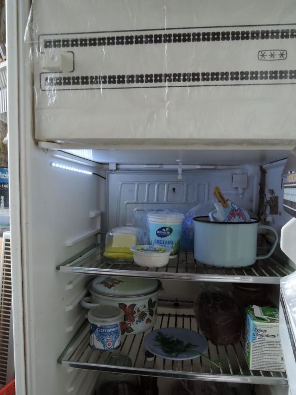
View with an open door during the day ...
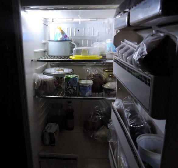
And the view with the door open at night


