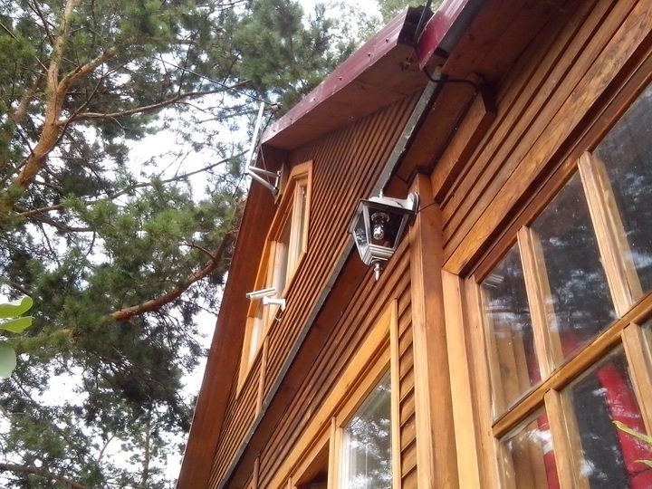
This switch is needed in the country to automatically turn on the LED lighting of the porch, path, entrance (toilet), etc. with the coming of night. In the morning with sunrise, the twilight switch automatically turns off the lighting.
It was like an order - to make a simple, reliable vandal-resistant twilight switch for an existing 12V LED lamp.
The existing Chinese night lights either on 220V, or on a weak battery in the form of a pin stuck into the ground ... Duck pulled out of the ground, like a carrot, and dragged away ... These are the realities we have.
A small digression. For the starting point, a << Light Detector >> LL1 01 was found, which was purchased long ago (along with security motion sensors). Shown in photo 1.
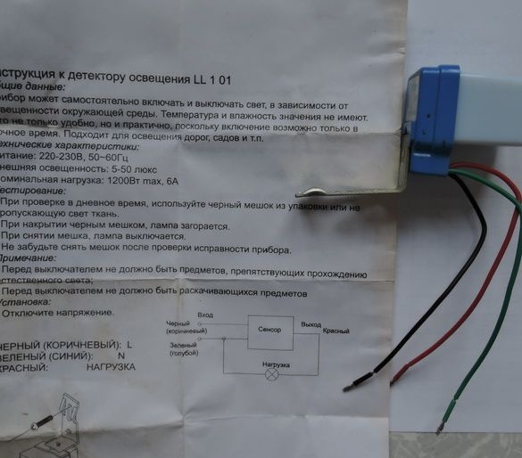
The instructions for the Lighting Detector are written in pure Russian.
I turn it on to 220V with a load in the form of a light bulb, as shown in the Instructions ... To measure, then, the illumination at which
this sensor is triggered. Since the instructions for the sensor indicate << Ambient light: 5 - 50 lux >>
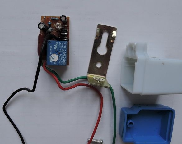
And nothing turns on. It just doesn't work. New one! In photo 2, the << Light Detector >> is shown disassembled.
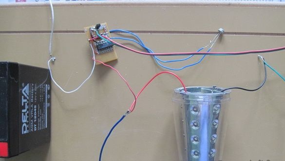
For the independent manufacture of the twilight switch, we need the following
elements and details (shown in photo 3):
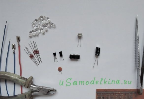
- resistors MLT-0.125 ~ 9pcs.;
- transistor 2SC2331;
- transistor 2SA1015;
- chip KR561TL1;
- photoresistor - FR1;
- LEDs -15 pcs. (you can use the finished lamp with 30 LEDs, as in this case);
- terminals for connecting to the battery (2 pcs.);
- mounting wire;
- a piece of universal scarf 28x45mm with holes in increments of 2.5mm;
- 12V battery (used existing DELTA DT12045 at 4.5 Ah);
- tools and supplies for installation (tweezers, side cutters, hacksaw, soldering iron (40 watts), POS61 solder, rosin);
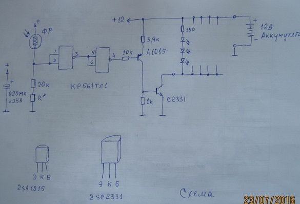
The diagram is shown in Fig. 1 (photo 4)
View of the welded scarf assembly is shown in photo 5.
The switch is configured (for this type of photoresistor) to operate under illumination ~ 3lux. A slight hysteresis is provided by the KR561TL1 microcircuit (imported analogue of CD4093). By adding feedback (positive) you can increase the hysteresis.
On current consumption (lamp is on) - 88 mA
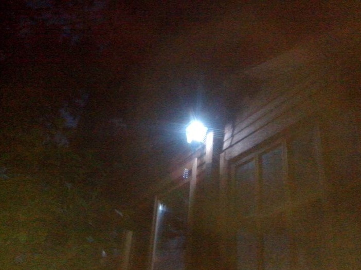
How it began to look at the country house is shown in photo 6 (during the day) and photo 7 (twilight or night).