

The proposed intercom provides two-way speakerphone between visitorand the owner of the house, apartment, cottage.
Deviceeats voltage of 12V, the current consumed by them does not exceed 150 mA.
The advantages of the proposed device:
The device is simple to manufacture and does not contain scarce parts, provides loud-speaking communication on any two-wire line at a distance of at least 100 m.
The device does not have microphones, and the functions of receiving and reproducing sound are performed by dynamic heads.
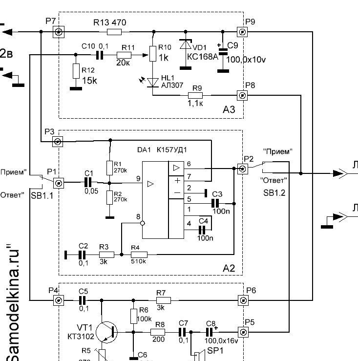
The intercom (PU) consists of two parts.
the device is located at the front door, and is located in a convenient place for the owner of the house. The dialogue between subscribers occurs by switching modes (“reception” - “answer”) with a button on the control panel.
The layout of the indoor unit [/ i] PU is shown in Fig. 1.
The composition includes:
- microphone amplifier on the transistor VT1 (block A1);
- universal amplifier of sound frequency (SP) on the DA1 chip - operational amplifier (OU) K157UD1 (block A2);
- power supply and switching unit PU (block A3).
The outdoor unit (Fig. 2) is formed by a microphone amplifier on transistors VT4, VT5 (block A5) and an electronic key on transistors VT2, VT3 (block A4) connecting the dynamic head SP2 to the communication line.
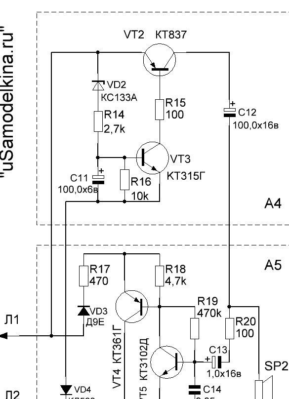
Fig. 2 Scheme of the external control unit
The intercom (PU) in the initial position is in the “Reception” mode, when the contacts of the mode switch button (SB1) occupy the position shown in the diagram (Fig. 1).
As soon as a sound is heard behind the door, it is converted by the dynamic head SP2 (A5) into an electric signal, which is amplified by a microphone amplifier (A5), and then an amplifier with an RF amplifier on the chip DA1 (A2), then it goes to the dynamic head SP1 (A1) that reproduces the sound on remote control pu.
To respond to the visitor, go to the “Answer” mode by pressing the SB1 button on the remote control. In this case, the circuit is switched. A dynamic head SP1 operating as a microphone of the internal unit of the device is connected to the input of the amplifier ЗЧ (А2) through the microphone amplifier (А1), and the output of the amplifier ЗЧ (А2) through the communication line (Л1, Л2) and opened electronic the key (A4) is connected to the dynamic head SP2 located in the outdoor unit.
Your voice from the control panel is amplified and goes to the SP2 head in the outdoor unit, and the visitor hears a response.By pressing and releasing the button on the remote control, we are talking with the visitor.
The length of the wires of the communication line can reach 100 m or more, without affecting the sound quality. This is achieved by pre-amplification of the RF signal by a microphone amplifier, which reduces the influence of interference and allows the use of even unshielded wires.
In addition to the elements indicated in the diagram, semiconductor devices similar in power and structure can be used in the intercom. The transistor VT5 in the outdoor unit must be low noise, the diode VD3 - germanium.
Diode VD1 - any of the series KD521, KD522. Oxide Capacitors - K50-6, K53-1; C2 - MBM, KM-6; the rest are ceramic types KM, KD. All resistors are MLT-0.125.
It is permissible to use a dynamic head SP1 with a power of at least 1 W and a voice coil resistance of 4 ... 8 Ohms in the indoor unit, and a small-sized head with a power of 0.25 ... 0.5 W of a voice coil resistance of 8 ... 50 in the outdoor SP2 Ohm (0.25GDSH-2; 0.1GD13-50).
It is convenient to use P2K switches or any similar ones as a power switch and SB1 button of the indoor unit (photo 2).
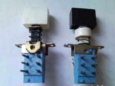
Photo 2 P2K Switches
Details are mounted (photo 3, 4) on a universal printed circuit board made of foil-coated PCB.
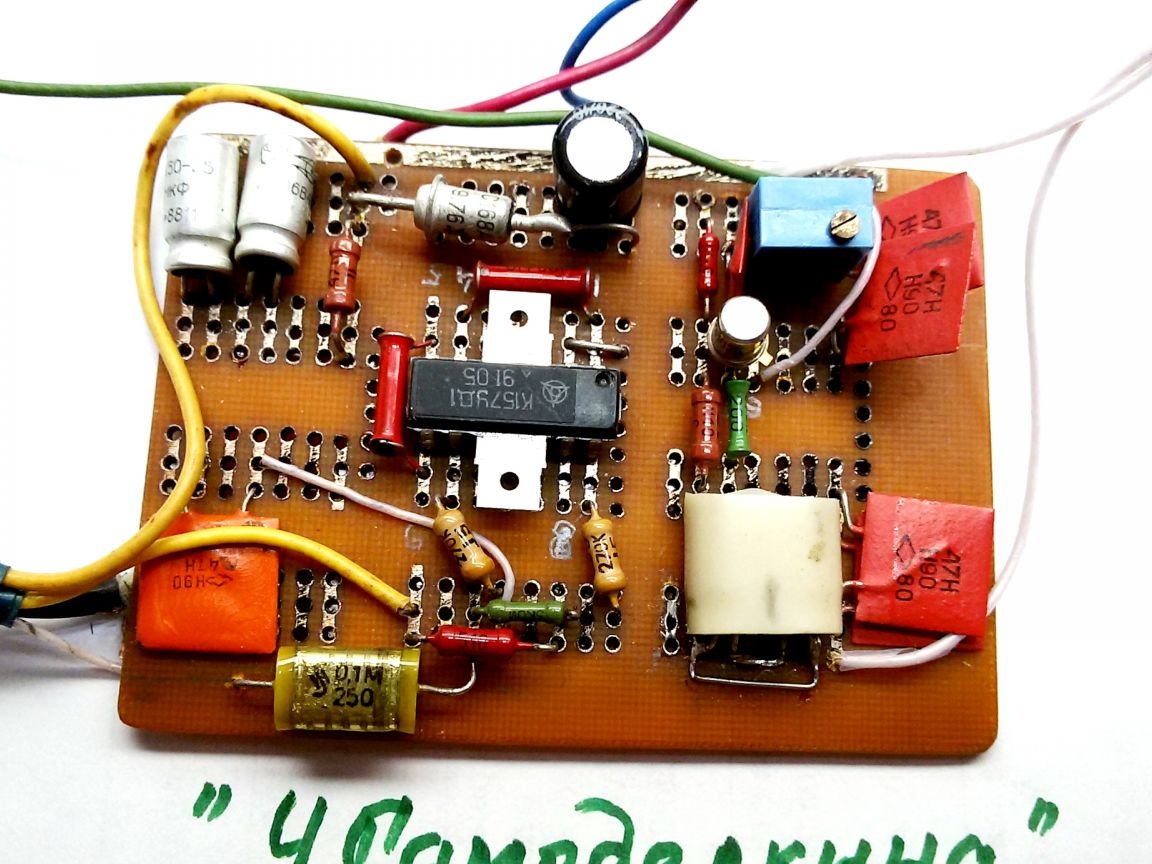
Photo 3 Indoor unit board
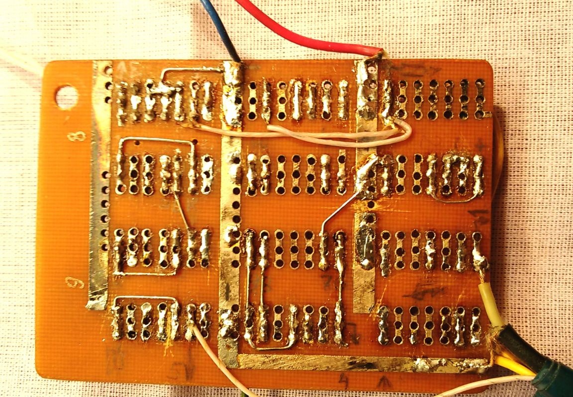
Photo 4 Indoor unit board [(back)
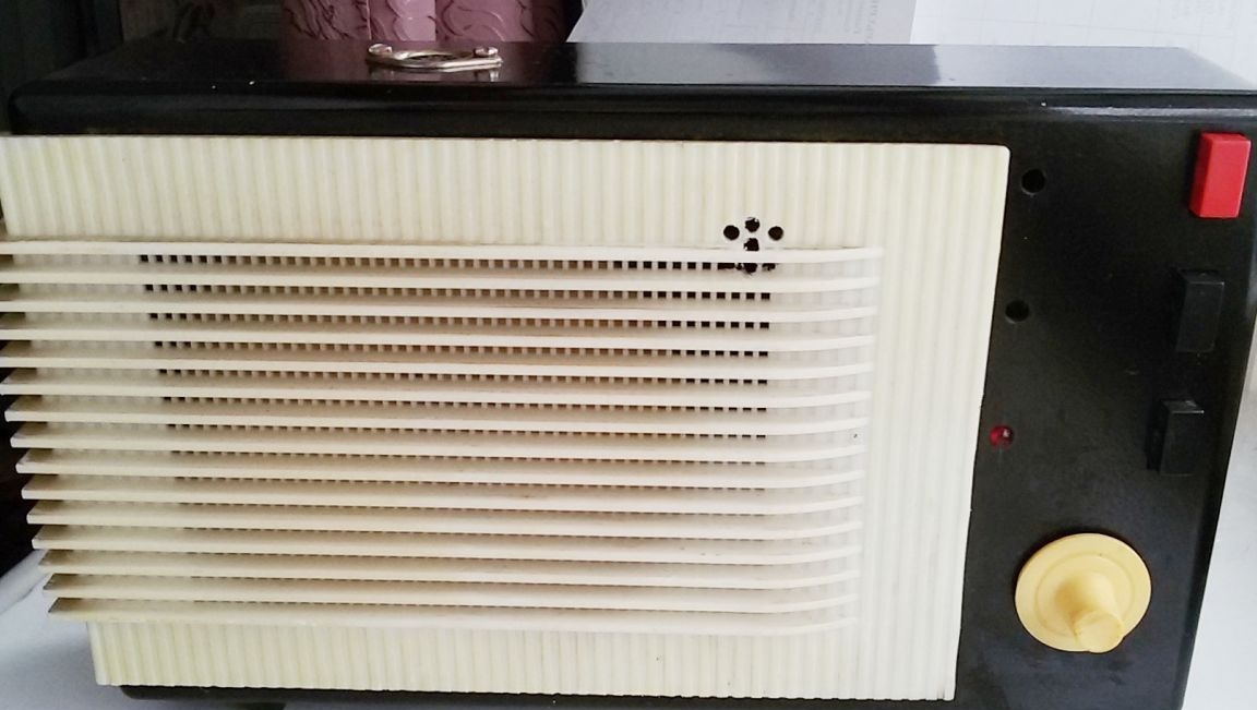
The board can be installed in a separate case, for example, from a subscriber loudspeaker (photos 1, 5) with a standard dynamic head, add a power supply, a button (“receive” - “answer”) and a connector for connecting the remote control to the communication line.
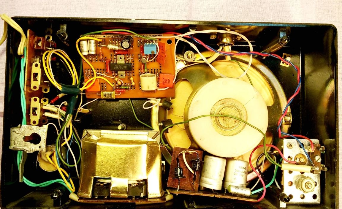
Photo 5 Remote control device
fix the devices on the inside of the front door (photo 6). Opposite the diffuser of the dynamic head SP2, in the door, drill holes with a diameter of 4 ... 7 mm and close them with a brass grid (photo 8, 12) to protect SP2.
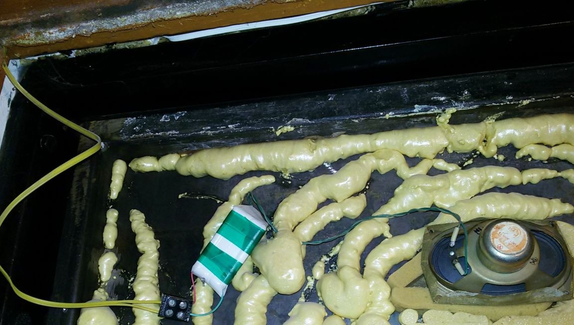
Photo 6 Location of the external unit on the door
Connect the external unit (photo 7-10) to the communication line with a flexible wire with a compensation loop - it eliminates wire breakage when opening the door (photo 11).
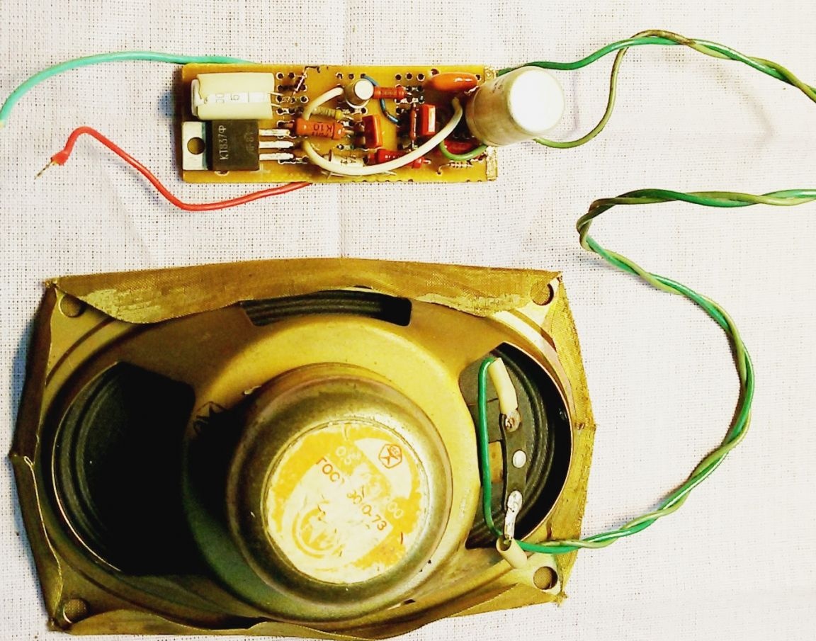
Photo 7 External part of the device
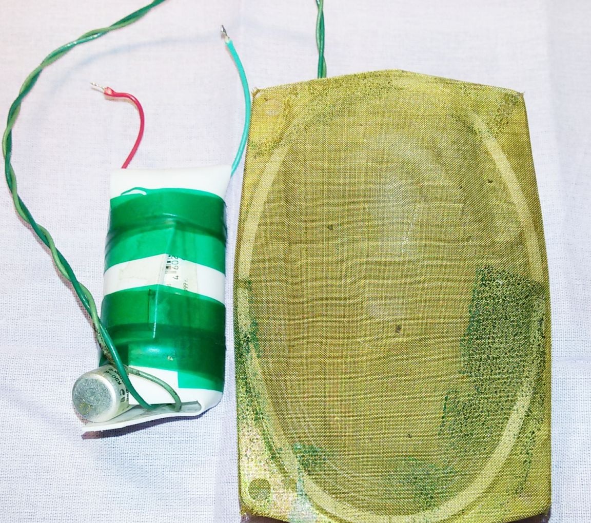
Photo 8 External unit before installation
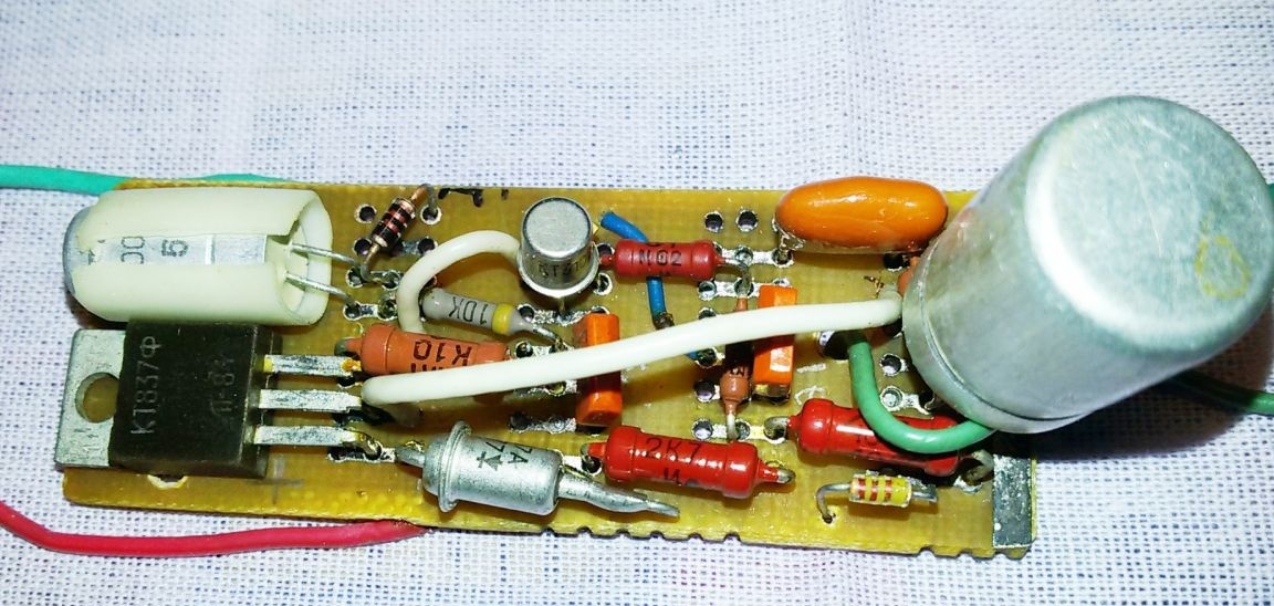
Photo 9 Microphone amplifier and electronic key
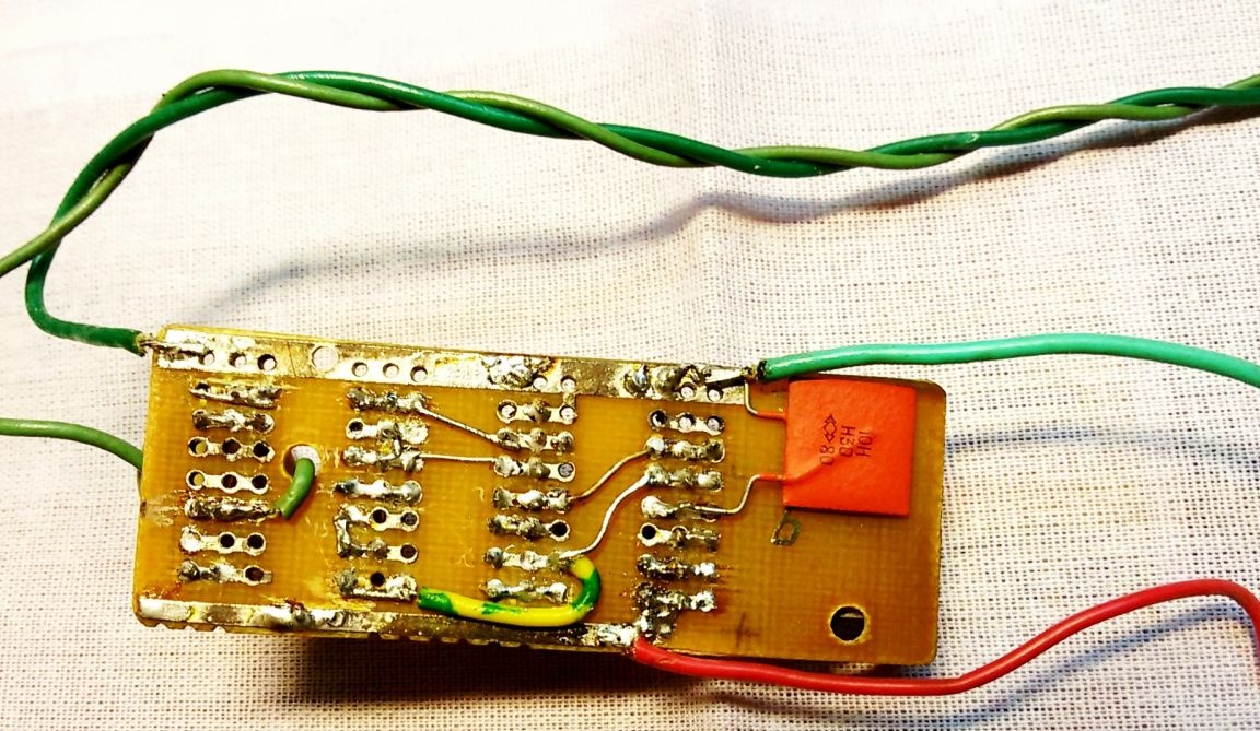
Photo 10 Outdoor unit board (back)
The commissioning of the PU begins with a check of the operation of the amplifier in the "Reception" mode.
By moving the outdoor unit to a distance that prevents the occurrence of acoustic feedback, check the quality of the sound signal.
If the amplifier is excited, you should move the connection point of the head SP1 to the common wire, as close as possible to the resistor R5 (A1). This resistor sets the cascade gain on the transistor VT1 so that the signal in the line is not distorted and is loud enough. The sound volume is controlled by a variable resistor R10.
Next, control the signal on the head SP2 of the outdoor unit. Sound quality is established by the selection of capacitors C6, C7 (A1) and C13, C14 (A5).
If necessary, by a simple refinement, the control room can be equipped with a call device. The operational amplifier K157UD1 in the RF amplifier can be replaced with another one that is similar in characteristics and with the appropriate strapping.
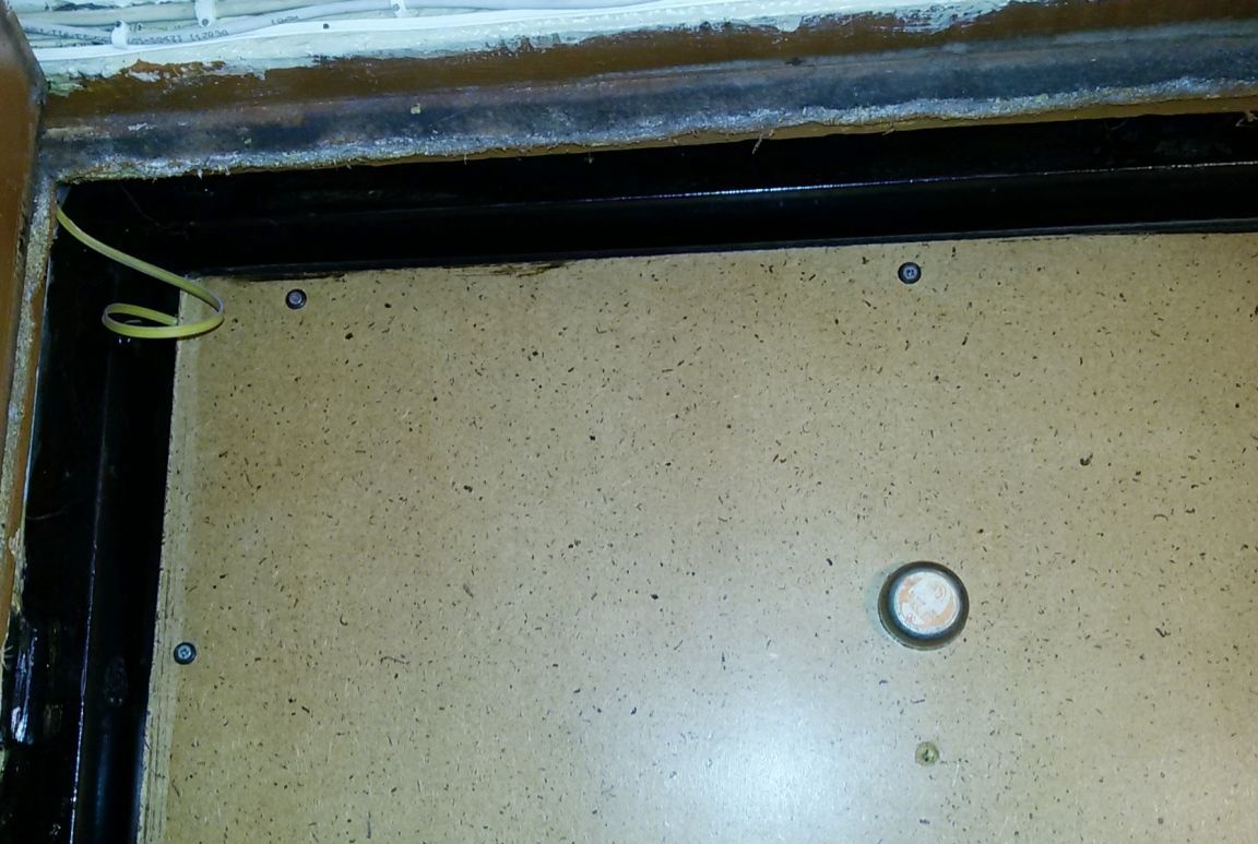
Photo 11 Exterior view of the door
Photo 12 External view of the door in the dynamic zone