

It will go as you understood about the LEDs, and where without them now. They quickly burst into our lives and exist to this day. That's crafts on this subject, too, a lot is obtained. I think everyone has at least one craft, and there is one with LEDs. Well, I throw my own to the heap. My lamps are not very original, everything is done simply, affordable, and most importantly, in my opinion, mobile. LEDs are a cool thing, they “eat” a little, but they shine decently. Moreover, the life of the LED is 50,000 hours. But until they broke the record of the “eternal light bulb” (unless of course we are beautifully deceived). This light bulb has been hanging and burning for 110 years in the American city of Livermore, California. The light bulb is located in the fire section of this city. It is known that it was manufactured by Shelby Electric Company. The miracle bulb has its own web camera and everyone can take a look at it online. A little distracted from the topic and I suffered ... but oh well, it does not hurt !!!!!
I've got garagebut no electricity. It turns out very uncomfortable in the evening, you put the car in the garage, and then you shine a flashlight and look for all your good. Unfortunately, there is no way to connect to electricity yet. That's why I decided to make home-made LED lamps. So, it’s decided, I’m making LED lights.
What we need:
Old fluorescent light (18.36.58 W)
LED strip in white and preferably warm 12 V (new)
ШВВП 2х0.75 wire (length depends on the connection point)
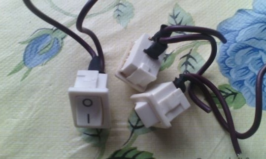
Toggle switch (optional)
Connecting wires (quite a bit)
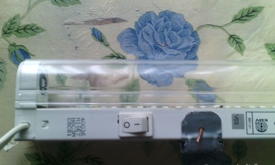
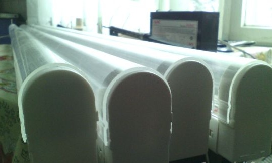
The whole process took me about 3 hours for one lamp. Given the fact that I completely washed and wiped it. It is not difficult to do it and I will briefly describe the whole process. I took a single fluorescent lamp, in which stood a 36 watt fluorescent lamp. It didn’t work out to take a full picture, it hurts too long. There is only a beginning and an end.
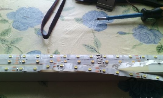
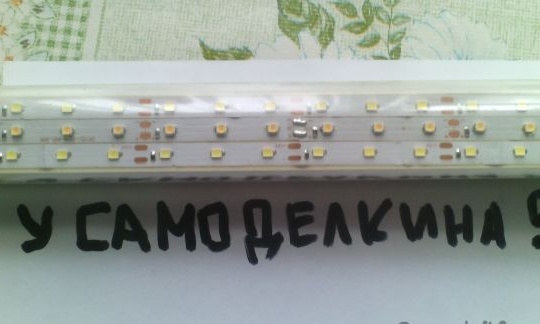
As you can see, 3 tapes “fit” in width. I glued 2 white ribbons on the sides and one warm in the center. Warm glued for better color reproduction.
Next, you need to connect all 3 tapes in parallel. I did it at one end of the lamp. Do not forget to observe the polarity.
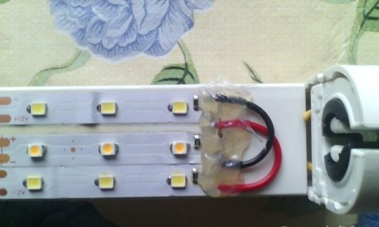
Top sealed with a gun-snot :)
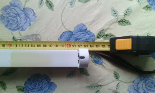
From the opposite end, I feed the tape and also seal it. I solder for any plus or minus. I hide the wires inside the lamp housing.
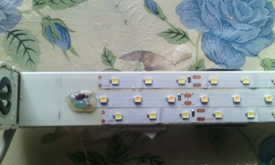
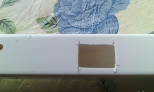
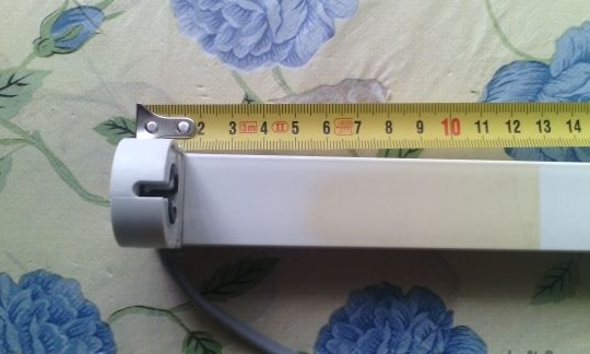
On the side I brought the ball screw, which I will connect to 12v
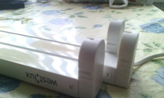
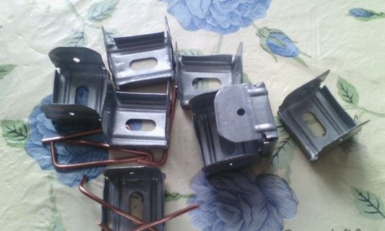
From the clamps of another lamp (2x36), I made mounts for my LED. You can also just bend the shredder.
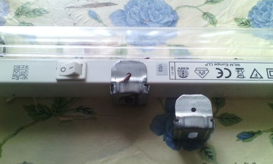
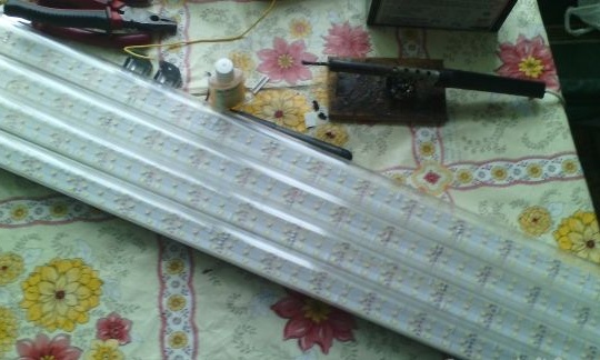
Lamps assembly.
Laboratory work No. 1 “Power measurements of LED lamp”
Given: Multimeter, battery, LED lamp.
Working process:
Measuring the voltage on the battery (Voltmeter)
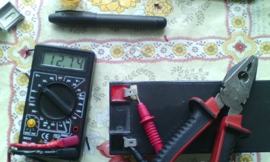
I = 0.9A; U = 12.7V;
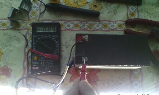
Here is a formula that will help us P = U * I
P = 12.7 * 0.9 = 11.43 watts.
As you can see from the calculations, one lamp consumes about 12 watts. And since I will use 4 lamps, it will approximately be about 50 watts, which is very economical. Especially in favor of the LED is the low power consumption and versatility of application (230 and 12 volts).
From the advantages of my design, I want to note: light weight, transparent corrugated diffuser gives a wide angle of illumination, quick-detachable design, built-in switch.
Conclusion: spending a little money on the purchase of LED strips on ebee and a bit of personal time, you can make excellent, economical, universal, long-running lamps.
All success in the creative industry !!!!