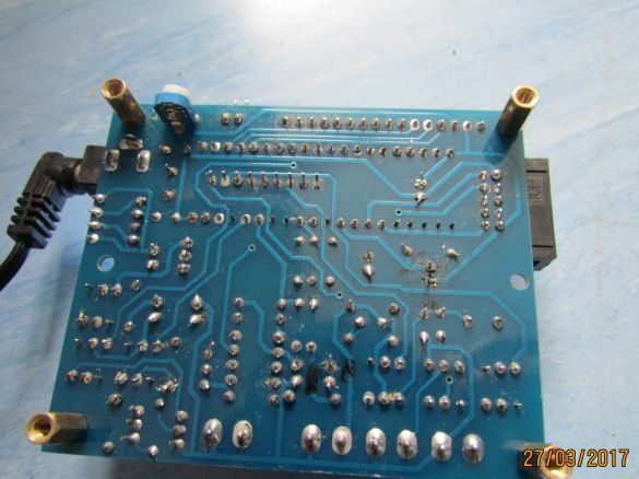
Hello everybody. I want to tell how to assemble a device designed to measure resistance, inductance and capacitance electronic .
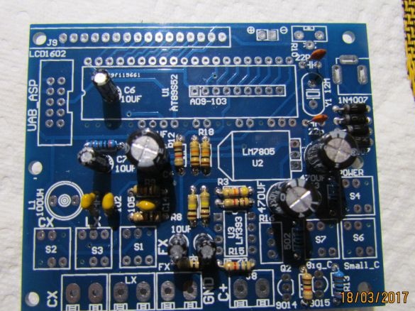
First, we install small parts, resistors and capacitors on the board.
After small parts we solder the larger ones .. the designations of the parts are drawn directly on the board, the main thing is not to mix anything up.
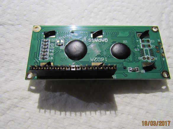
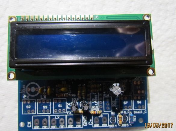
We solder the power bus to the display.
The microcircuits come with sockets for them - we solder the sockets, after we insert the microcircuits.
Last solder buttons and terminals, they are all the same.
When everything is soldered, wipe with a brush well with alcohol on the side where the soldering is.
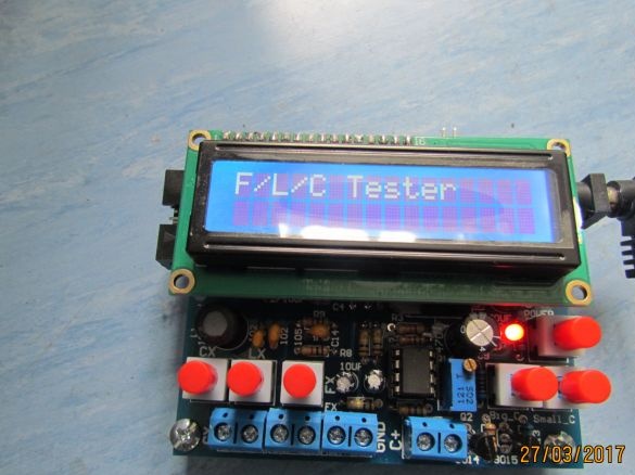
We connect 12 volts of alternating voltage through the socket, turn on the power - the red diode lights up and such an inscription should appear on the board, this indicates that everything is assembled correctly.

