

Hello to all lovers homemade. In this article I will tell you how to make a high voltage generator do it yourself, the application of which is quite wide, it can be used as power for gas discharge lamps, an ozonizer for etching rats. It is also ideal for creating a shocker or electric ignition of gas. I think many became interested in how to assemble it, so we do not delay it and proceed to the assembly, the very device is based on a blocking generator.
But before reading the detailed assembly, I suggest watching a video where you can clearly see the principle of the homemade action and understand if I need it.
In order to make a high-voltage generator with your own hands, you will need:
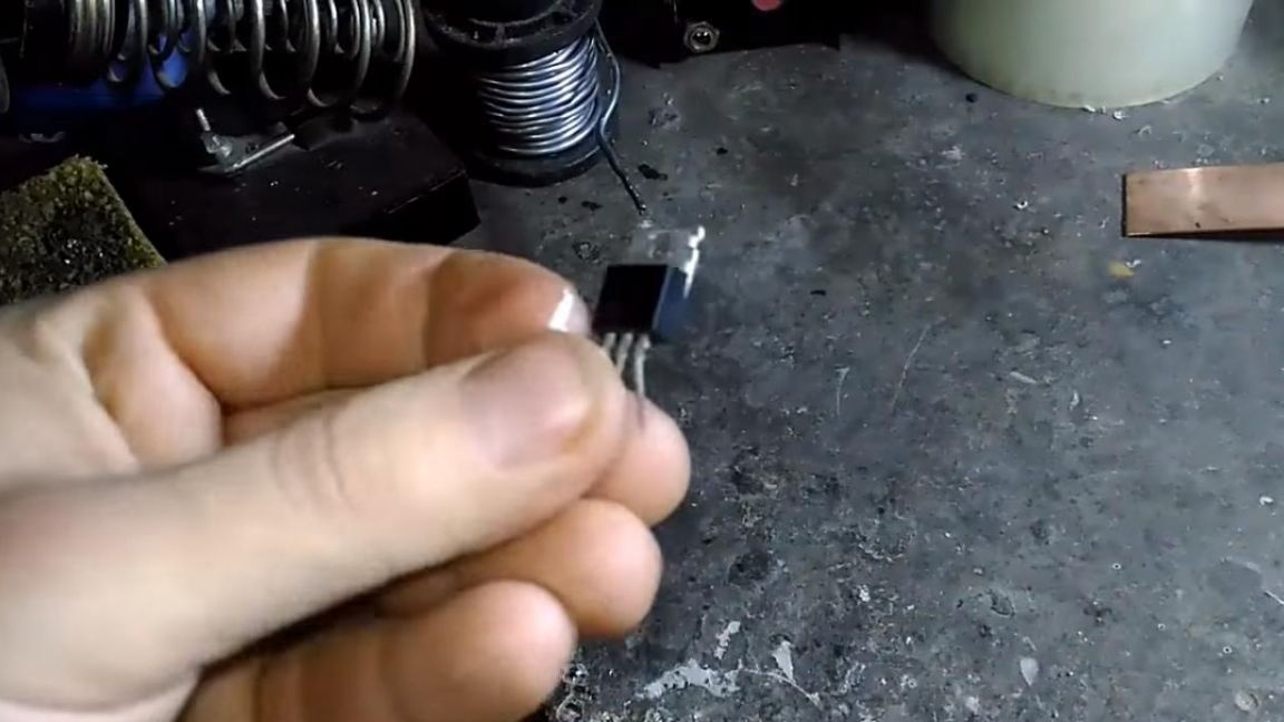
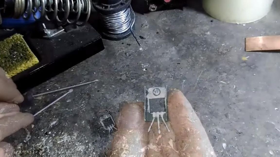
* IRF3205 transistor with heatsink
* 18650 battery
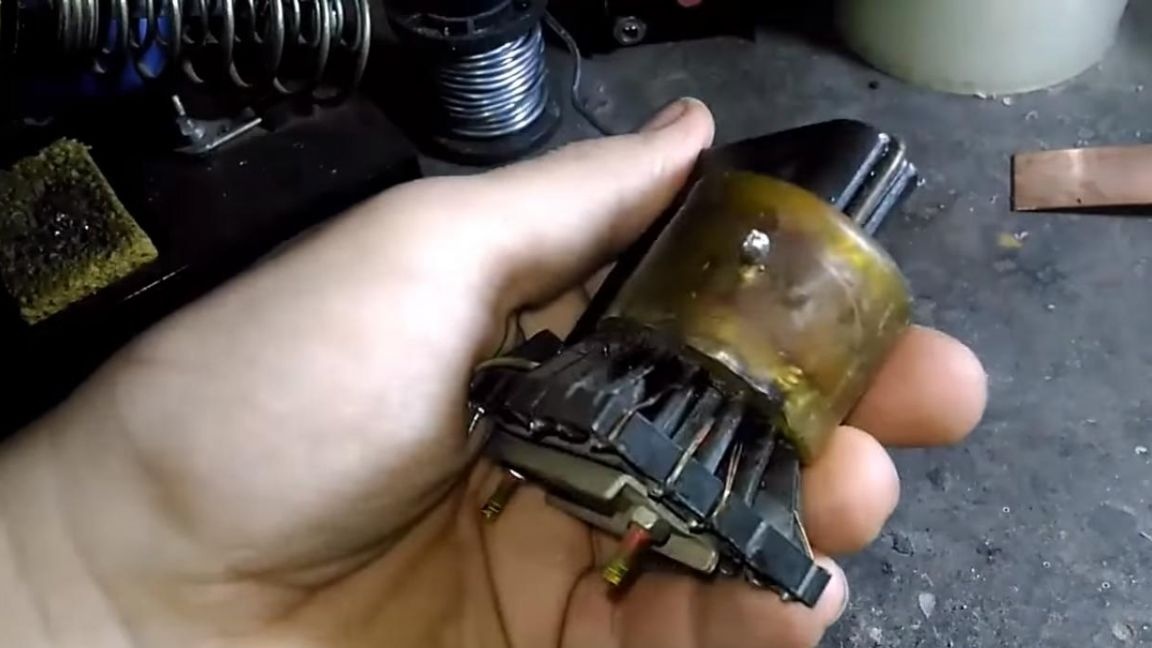
* Multiplier
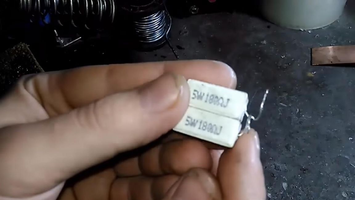
* 100 ohm resistor
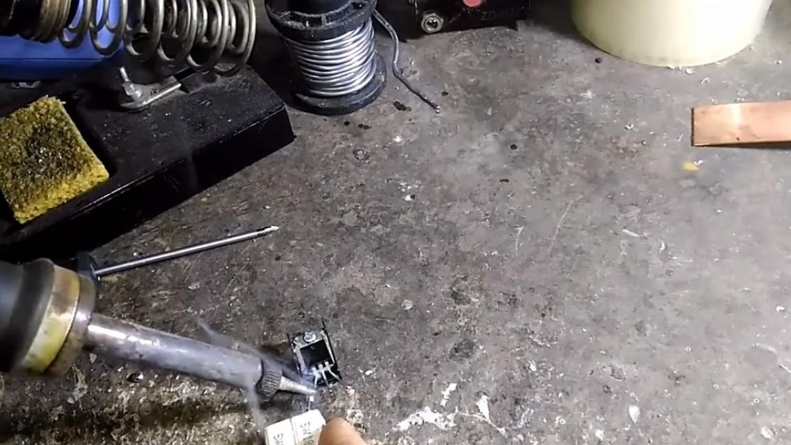
* Soldering iron, solder, flux
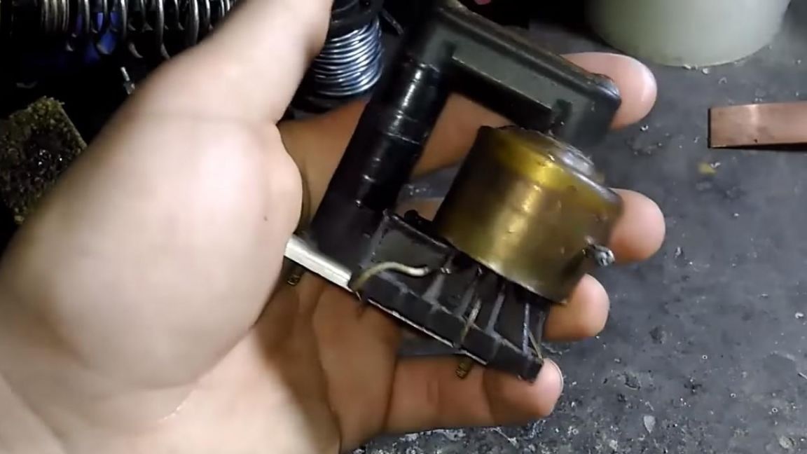
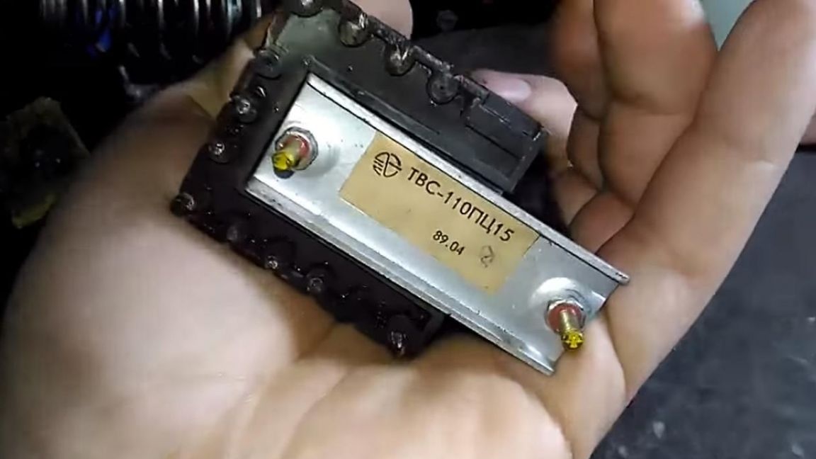
* Line transformer TVS-110PTs15
* Winding wire, diameter 1 mm and length 1 m
* Stationery knife or scalpel
* Wires
That's all that is needed to make this homemade product, I think it’s not so difficult to find all this, given that almost all the details were taken from the old TV.
Step one.
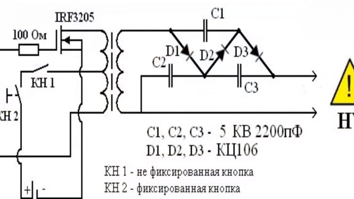
This transformer works according to a circuit diagram that is easy enough to repeat to any beginner in this business.
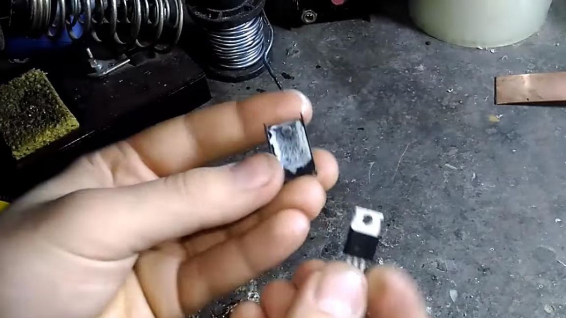
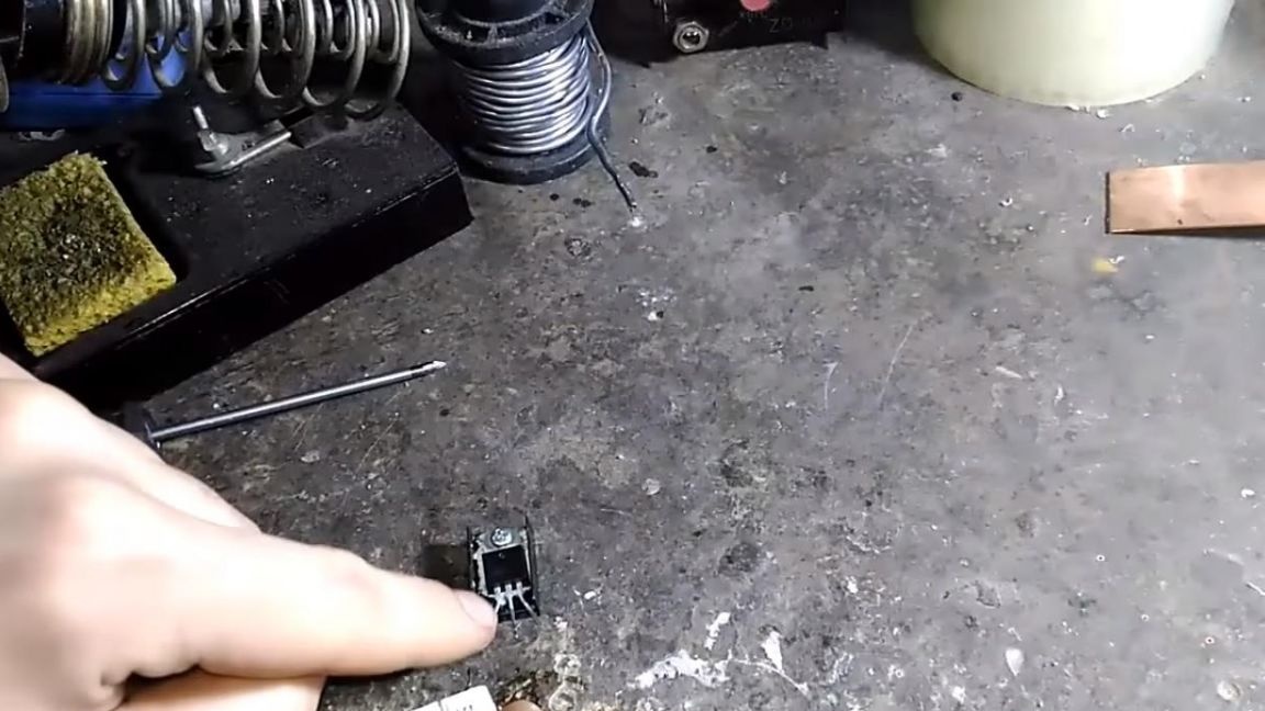
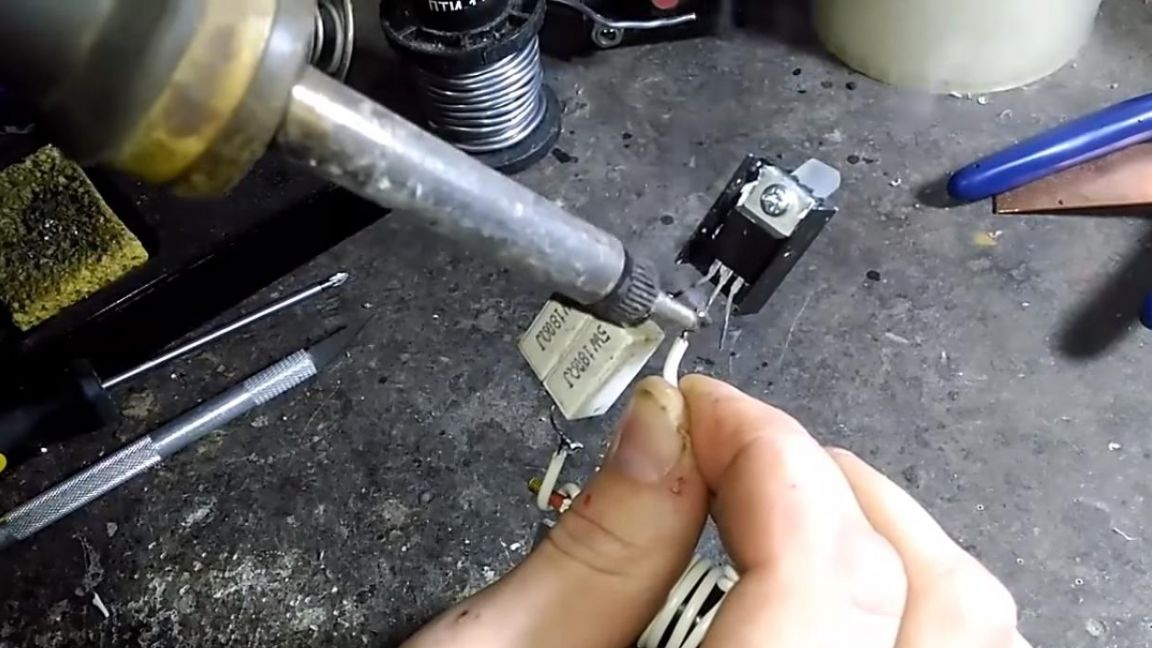
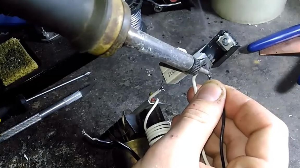
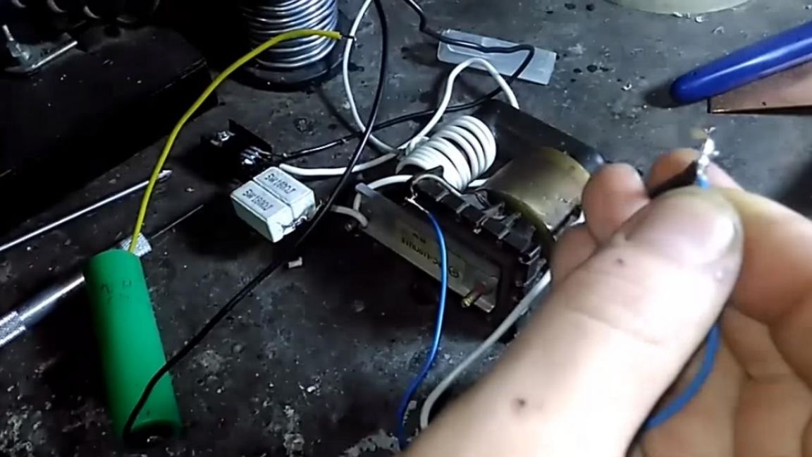
First of all, we take the IRF3205 transistor and fasten the radiator to it through thermal grease, since it will heat up during operation.
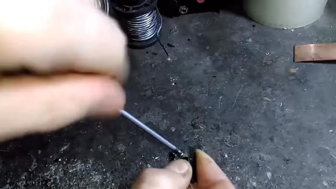
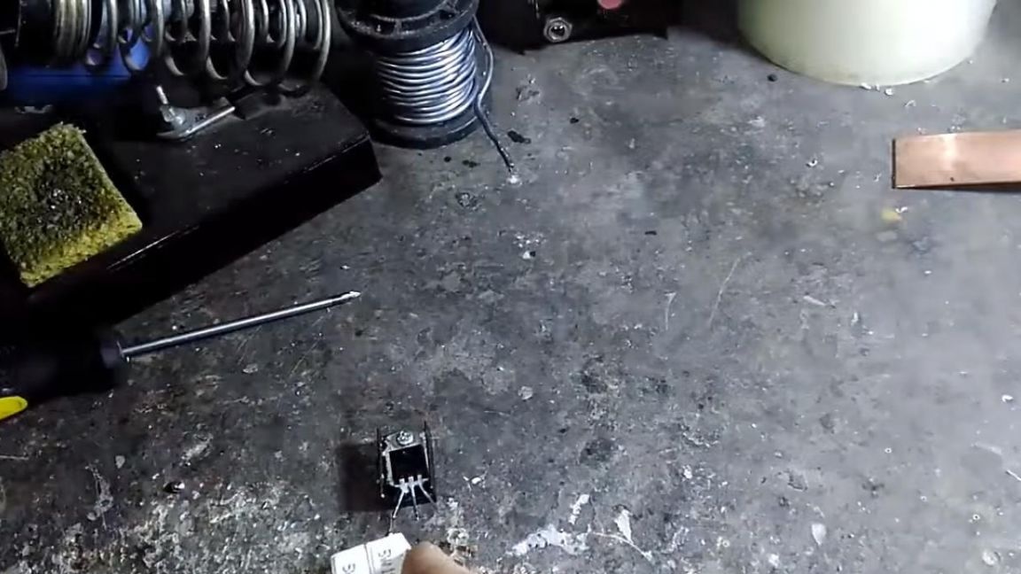
To the left leg of the transistor or to the gate we solder a 100 Ohm resistor, which in my case is assembled from two resistors connected in parallel.
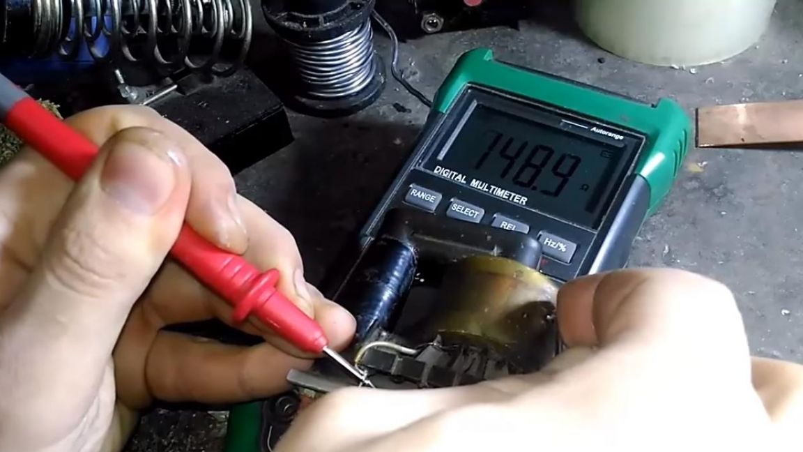
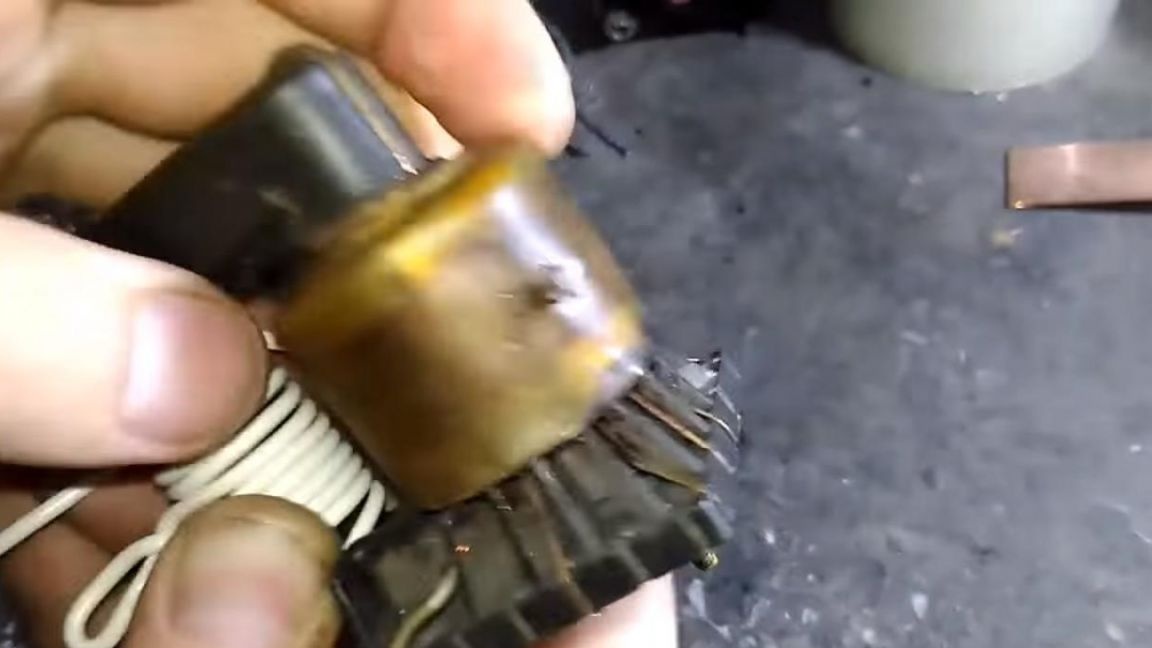
After the resistor is soldered, go to the line transformer, it can be found in almost every old TV, so do not rush to throw it away. The resistance of the secondary winding of this transformer is 150 Ohms.
Step Two
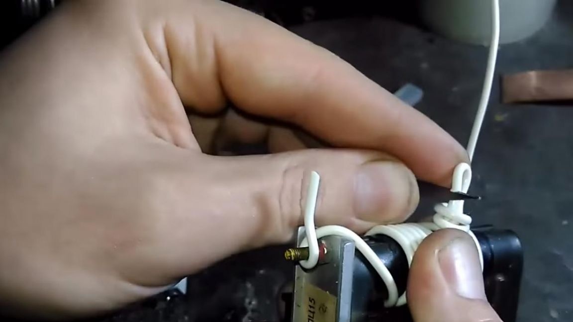
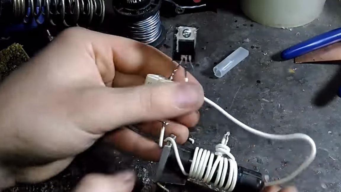
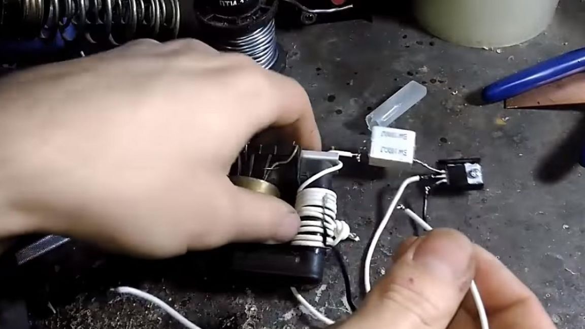
At this stage, it is necessary to wind 10 turns with a branch from the middle on the transformer, this is done with a winding wire, the diameter of which is 1 mm.
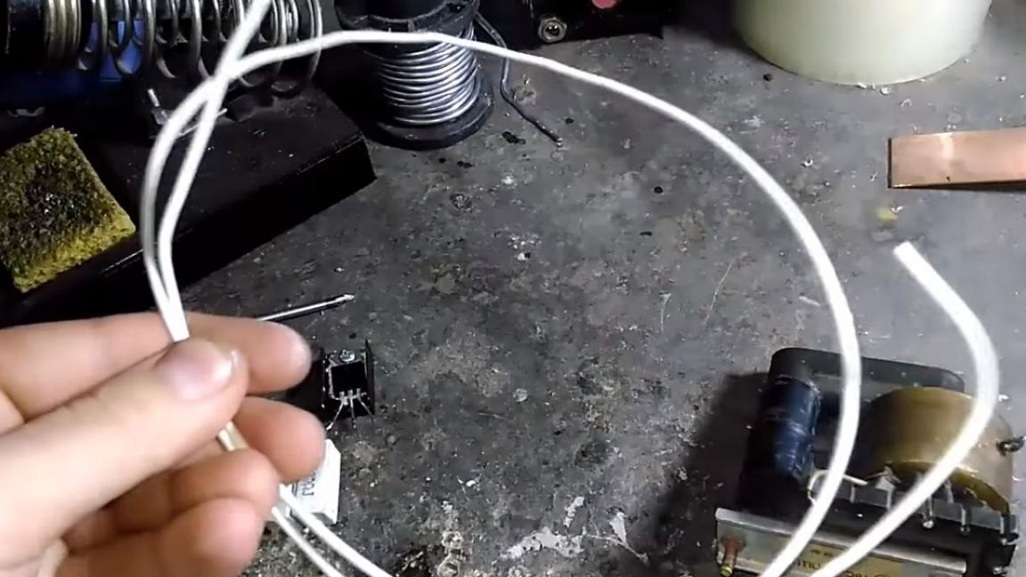
After winding 10 turns, it is necessary to strip the wires at the beginning and end, as well as remove part of the insulation from the middle wire.From experience I will say that it is most convenient to do this with a scalpel, purchased in China.
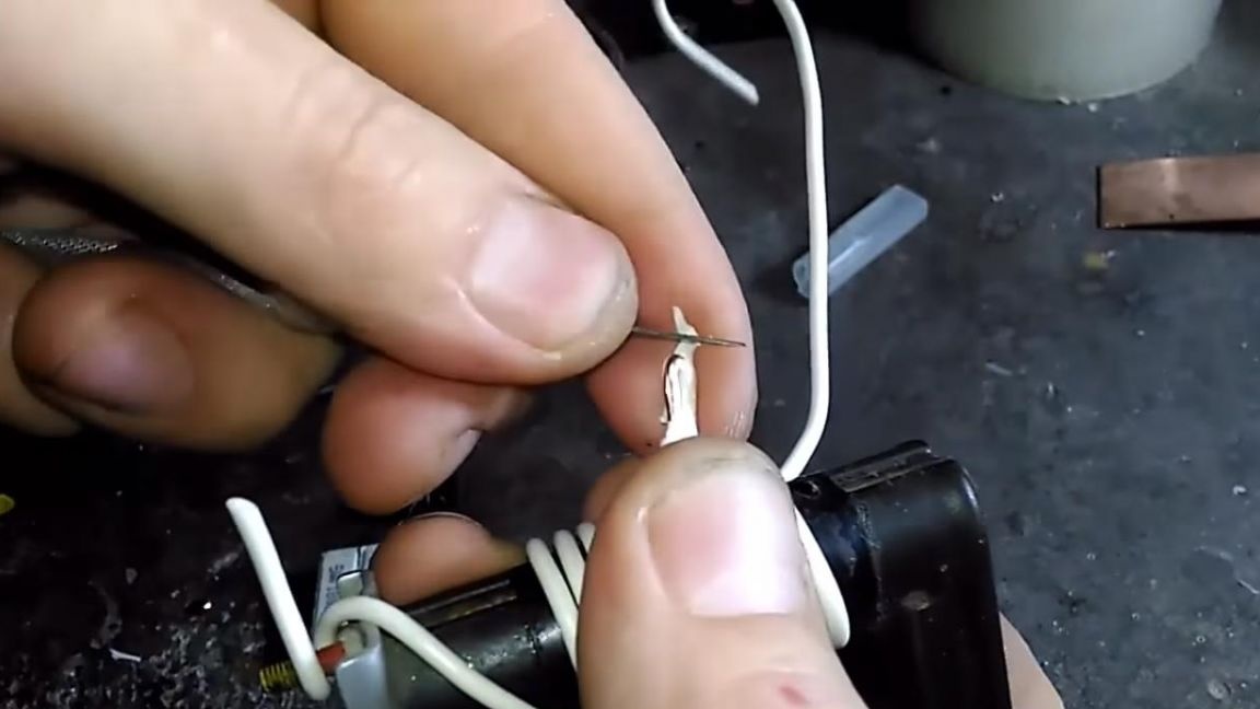
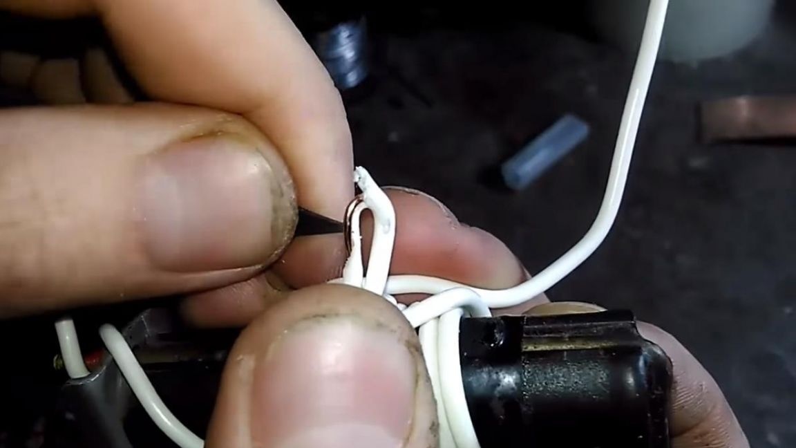
The bare wires can now be tinned by prematurely applying a flux to them. To the beginning of the winding, solder the second output of the resistor, which was previously soldered to the transistor.
The second end of the winding is soldered to the drain or to the middle terminal of the transistor.
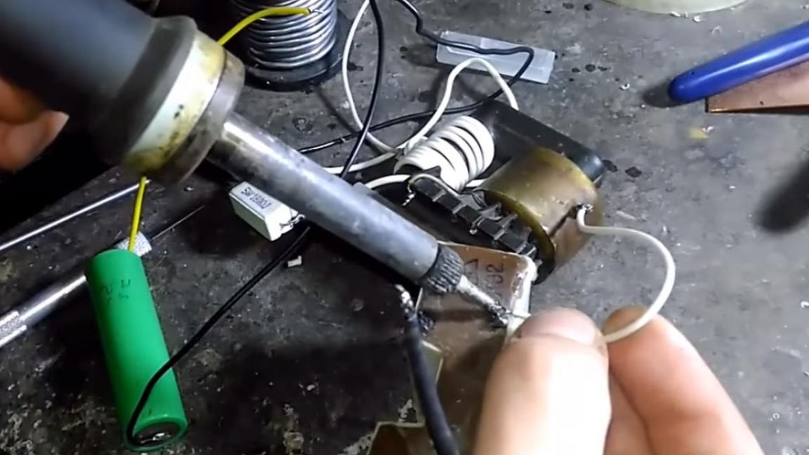
To the far right terminal of the transistor or the source, solder another wire.
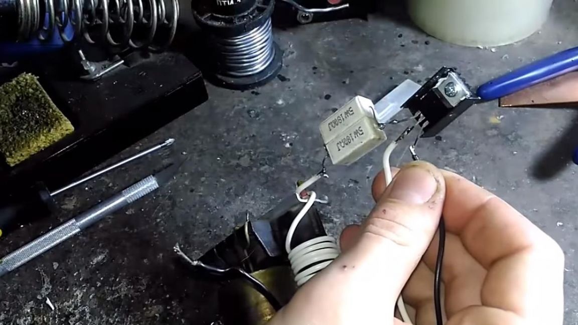
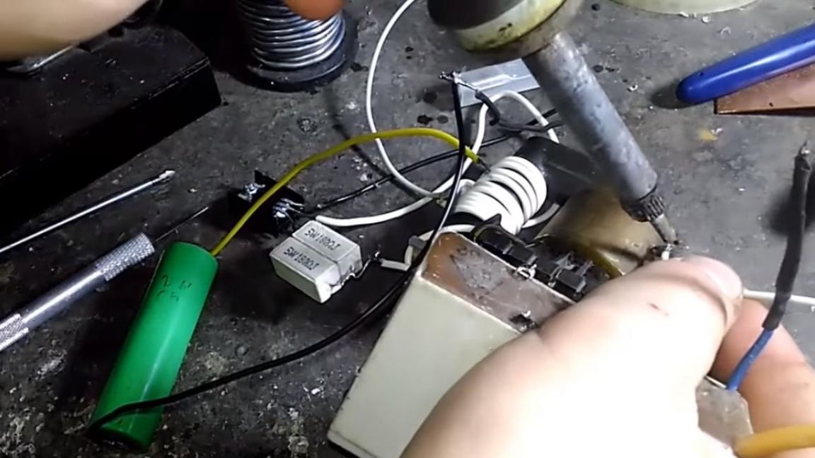
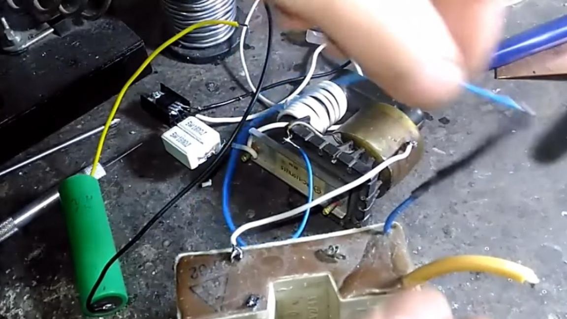
Solder the wire to the tap from the middle of the winding and solder another wire to the terminal of the secondary winding of the transformer.
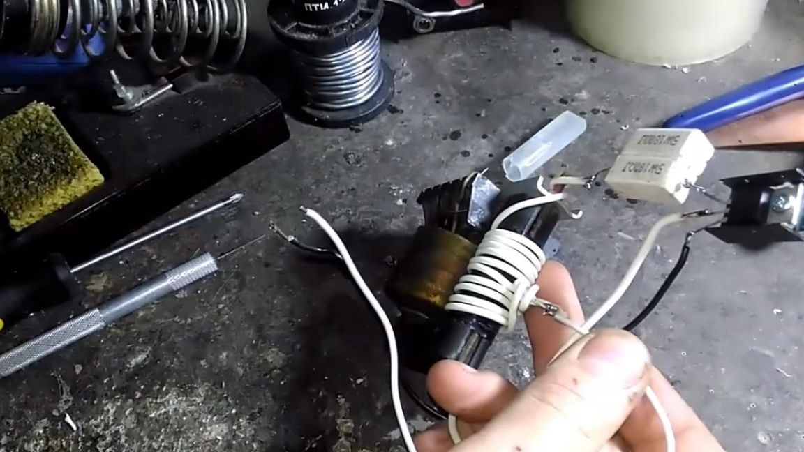
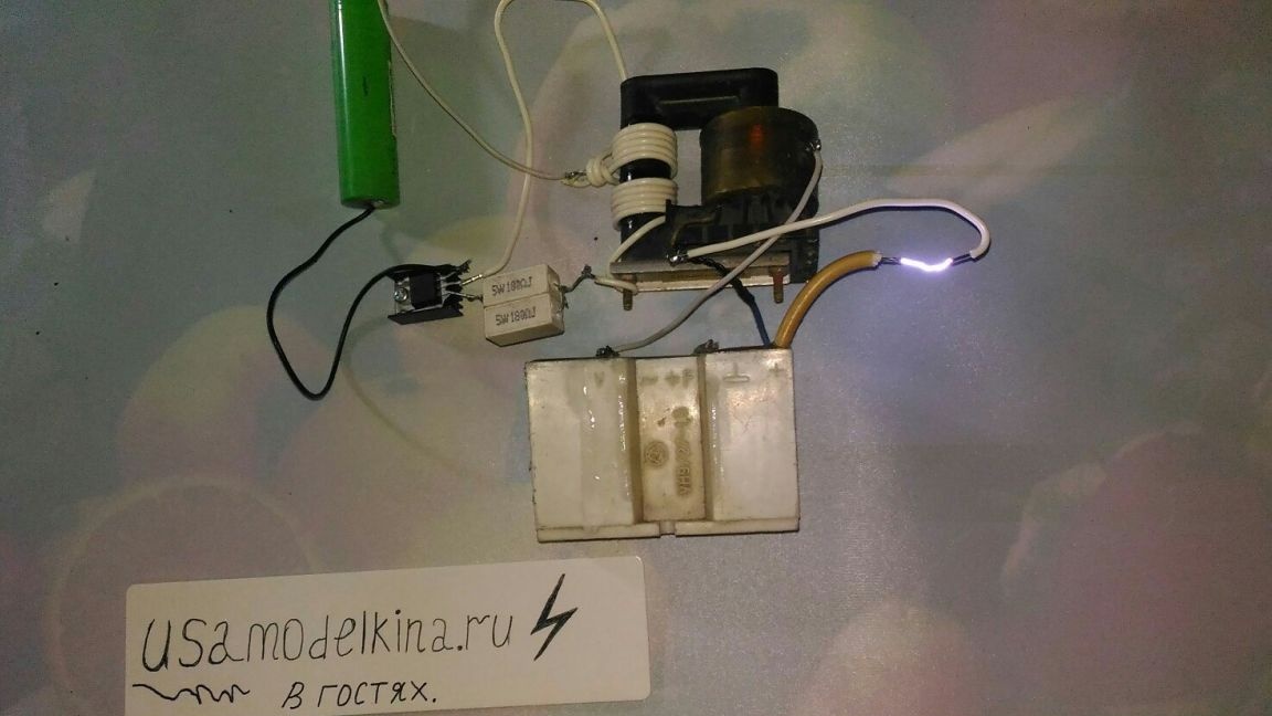
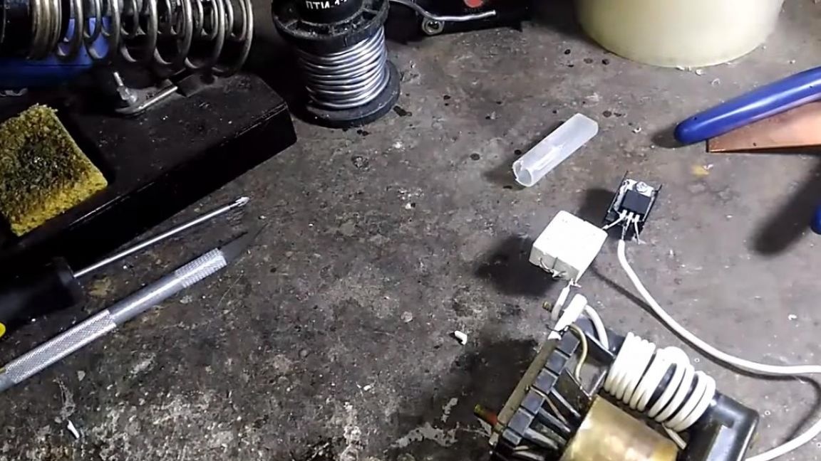
Now you can try the transformer to work, by connecting a 3.7 volt 18650 battery to the source of the transistor and to the tap from the middle of the winding, we get an output voltage of 5 kilovolts on the transformer, the arc is visible, but it is too small.
Step Three
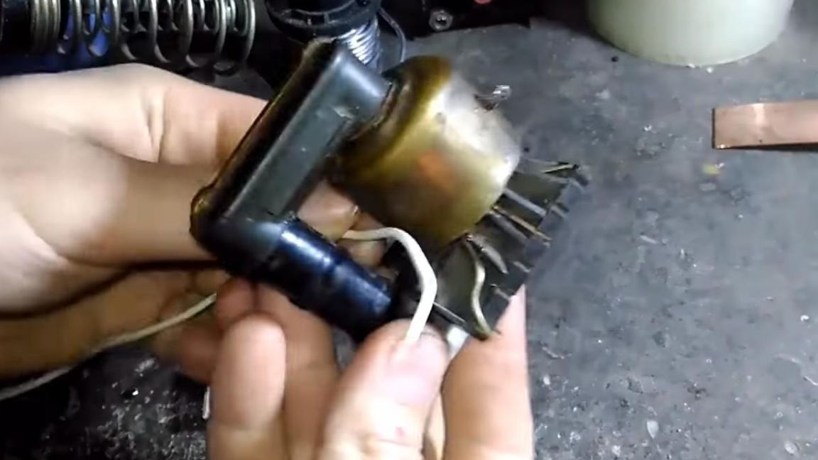
You can increase the output voltage using a multiplier, this option will increase the voltage from 5 kilovolts to 20.
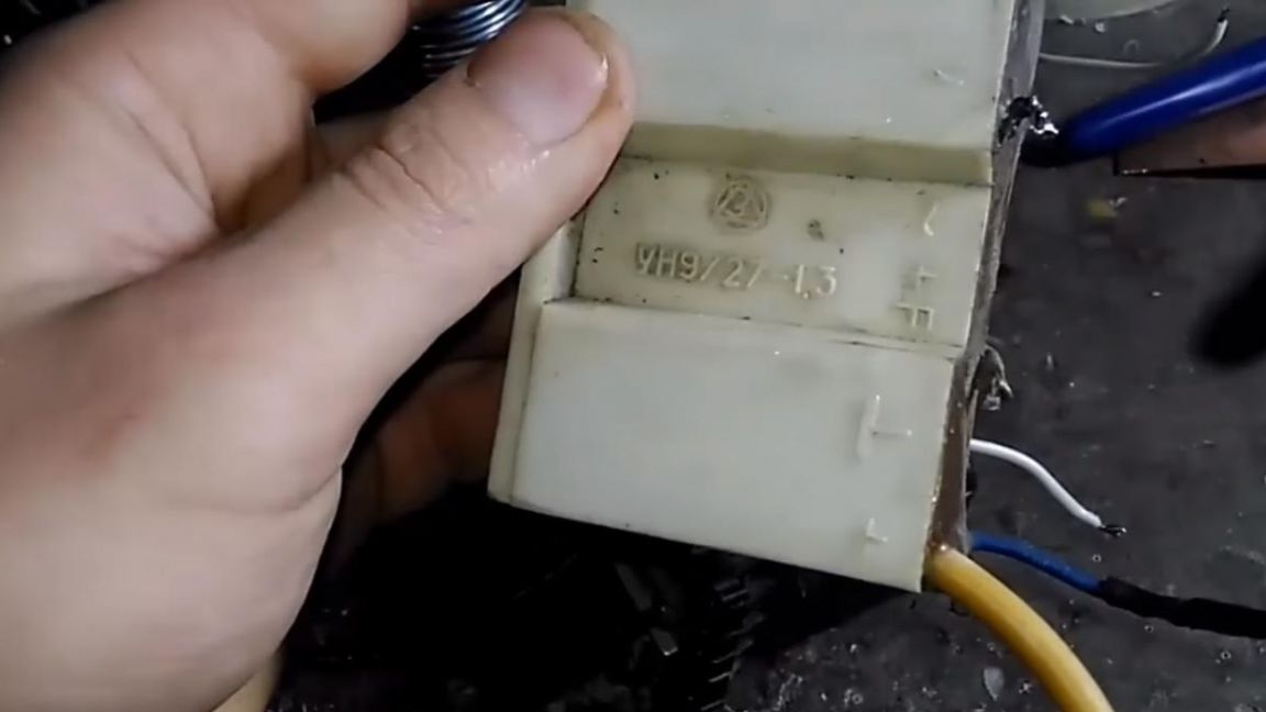
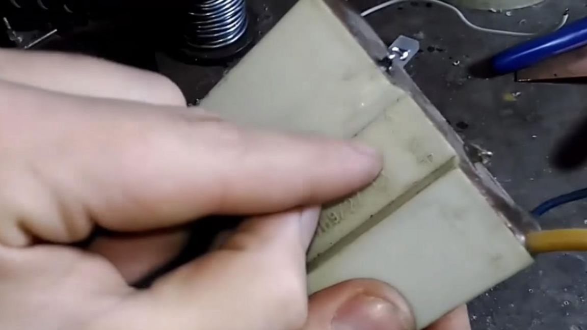
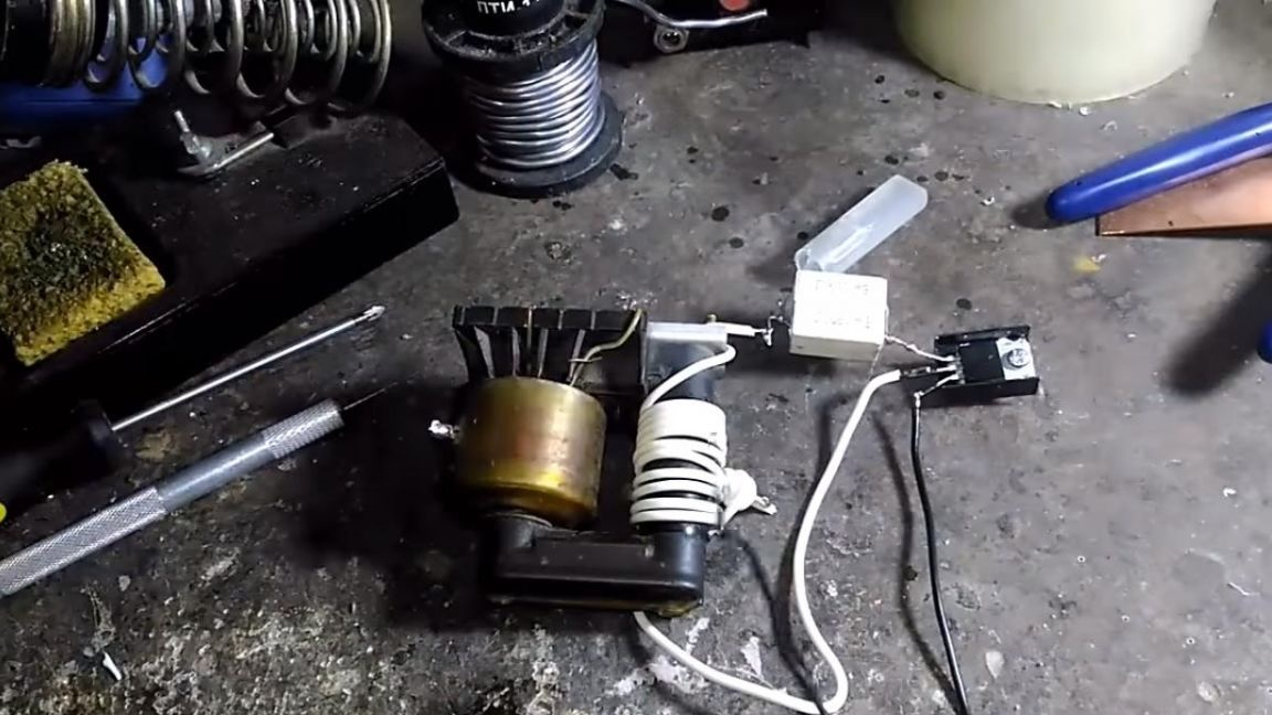
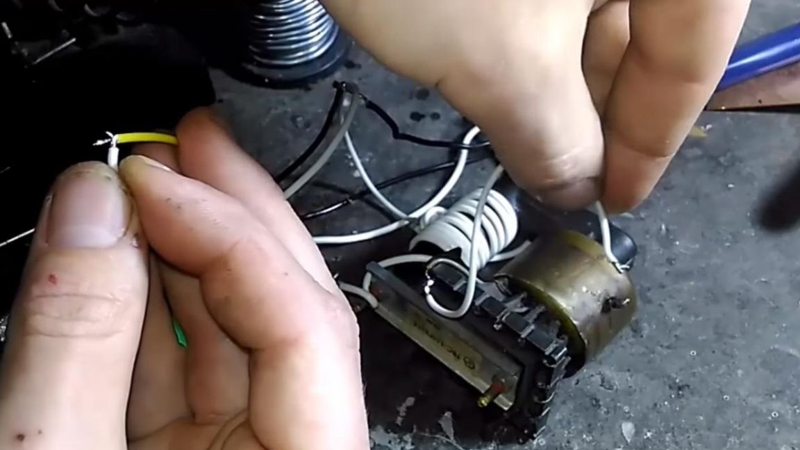
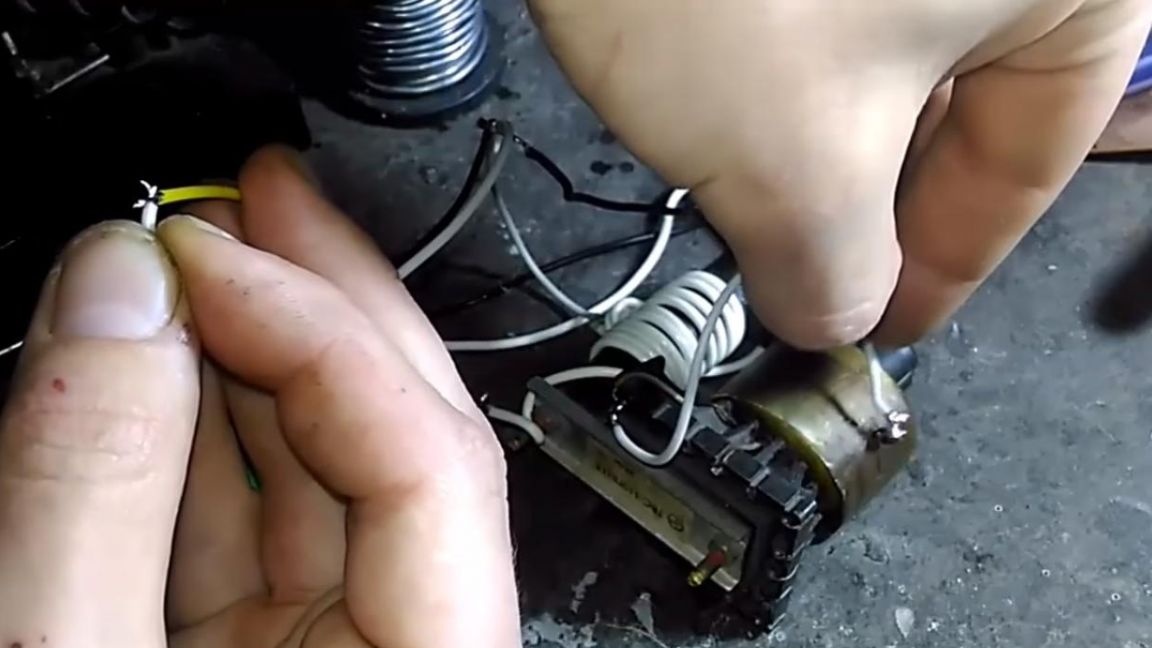
Such a multiplier will also not be difficult to find, as it is often found in old televisions of the USSR. From the output of the transformer, solder the wires to the multiplier, as a result, on the contacts of the multiplier we get a fairly good large arc, which can be further applied in various projects.
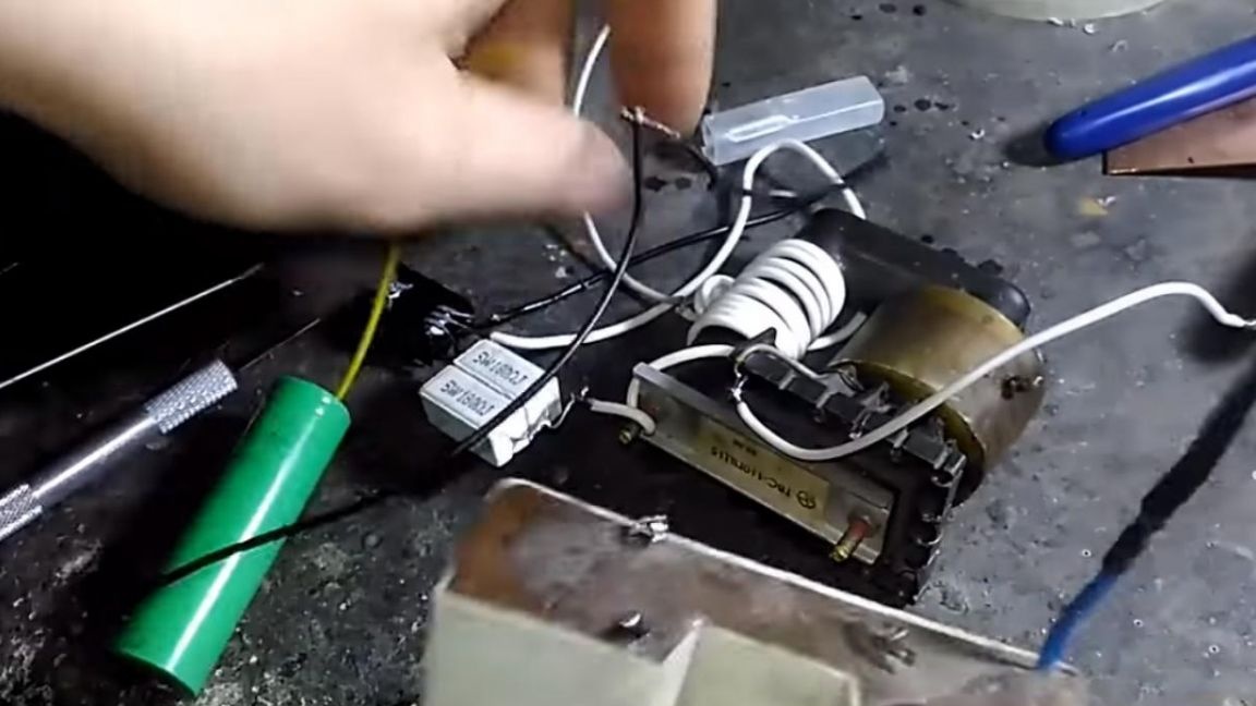
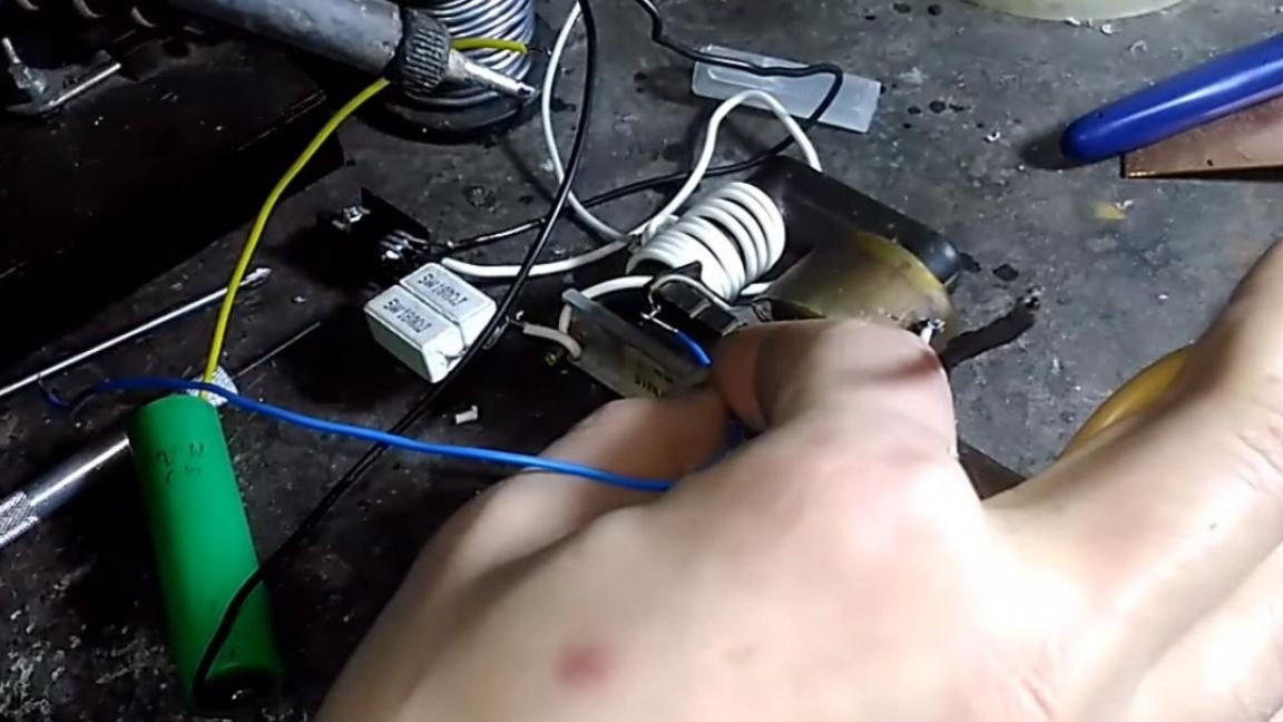
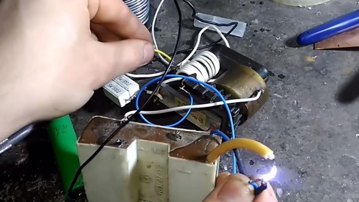
During the test, the generator worked properly, it also turned out to power a discharge lamp from it, which can also be useful to someone.
That's all for me, thanks for your attention and all the creative successes.