

So, the final part of tetralogy about creating a device for producing carburetor gas (gasoline vapors) for burning them in a large tabletop glass-blowing burner. Let me remind you that this whole epic using gasoline instead of the usual gas was started for several purposes. First and foremost - the temperature of the torch of a gasoline vapor burner is slightly higher than even propane (with air blasting), not to mention natural gas. Considering that blanks for glass-blowing from low-melting glass have become exotic and only glass that requires elevated temperatures (oxygen) to be processed on the burner, obtaining high temperatures suitable for high-melting glass using alternative methods without using oxygen in cylinders is a worthy task ( complete replacement of oxygen is achieved by adding a small amount of detonating gas from the electrolyzer to gasoline vapors). A pleasant moment is the delivery of compact liquid fuel to a workshop remote from the roads. There are a few minor positive points that were mentioned earlier.
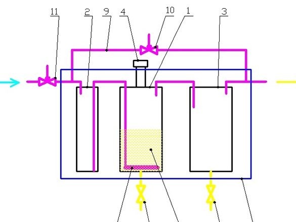
The description of the device, the algorithm of its operation and the manufacture of a gasoline trap (pos. 2) were described in part 1, the manufacture of a bubbler (pos. 1) in part 2, the manufacture of a condenser (pos. 3) and the connection of all three tanks, in part 3.
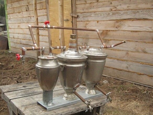
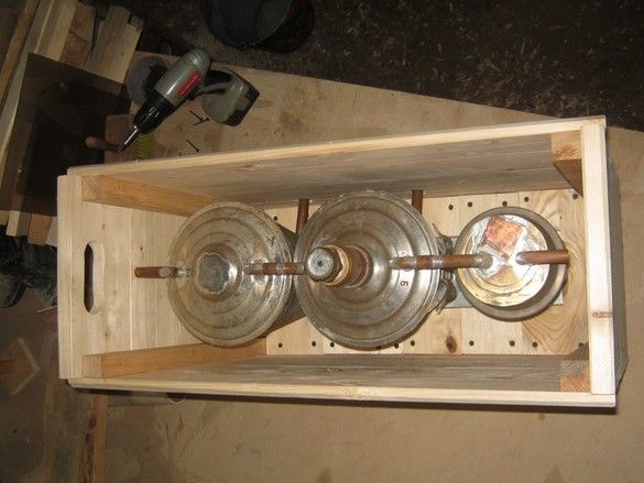
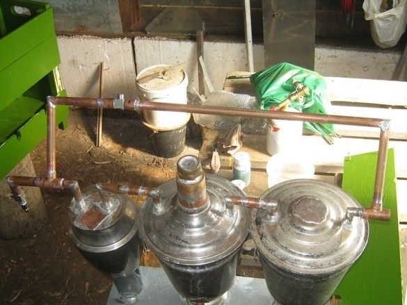
So, our device is ready in general and consists of all three tanks 1,2,3 with the corresponding nozzles and insides. The tanks are connected and mounted (soldered) on a tin stand. The remaining work should be carried out in the order they are followed: manufacturing a box 12, bending and installing a bypass 9 with an overflow needle valve 10, manufacturing and installing an inlet and outlet pipe (everything that sticks out of the box will have to be mounted in place). Installation of a heating cable on a bubbler, installation of tanks in a box and backfilling with sand. Installing a thermal controller.
Tools, equipment.
All connections were made by soldering - you need a manual gas burner. Set of bench tools. Medium size abrasive sanding pad for sanding soldering spots. For an accurate cut of copper tubes, it is convenient to use an end pendulum saw, or a miter box with a hacksaw will do.It came in handy electric grind, bench vise. In the manufacture of the box, a circular saw, a small planer and the same pendulum saw were used. Drilling machine, screwdriver. A few clamps. For painting - brush, dishes.
Materials
Copper sheets and brass trimmings were used, copper tubes 15mm, 18mm diameter. Special tees and couplings are parts of a copper water pipe. Two small needle taps, pieces of iron from old plumbing fixtures. Tin-copper solder No. 3, flux to it. Brush. LKM, cotton rags. Glue - joiner's PVA.
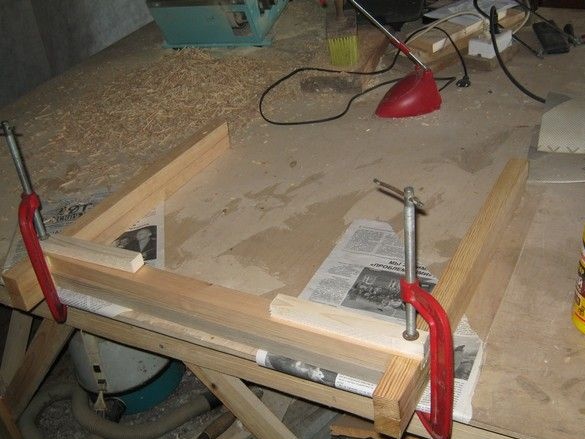
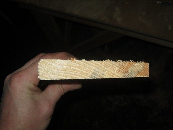
So. He took up the box. Prepared wood - for the frame, strong, resinous bars without knots and flaws, for sheathing trim boards. The frame bars were laid out. I connected it “in half the tree” to the joiner's PVA, checked the rectangularity with a large joiner's square, clamped it with clamps on a flat table. In the photo there is a drying frame, two pieces one above the other.
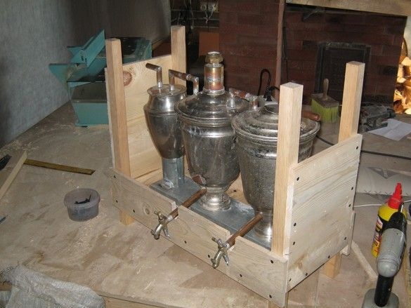
After drying, began to sheathe. Planks and trimmings of a suitable length were planed to a thickness of 12 ... 15 mm, cut to size, drilled holes for fasteners, screwed with screws. He made cuts for the protruding drain pipes, in the future they will be additionally covered with tin plates.
Almost a finished box, the case for the handles for transportation. As pens, it was decided to adapt the last (upper) planks of the box ends. To do this, he cut out their increased thickness so that it would be comfortable to hold with his hand, and in order to beautifully dock the bottom of the “handle” with thin lining, we had to make a conical blank.
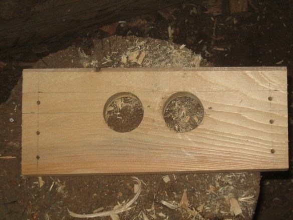
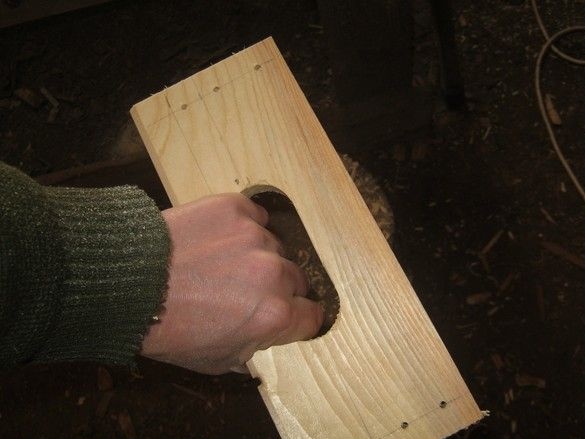
After marking the handle, I drilled the edges of the opening for the hand with a pen drill on a large (40 mm) diameter tree, connected the holes with an electric jigsaw, sanded large burrs with a sandpaper.
After installing the handles in place, the remaining blanks of the sidewalls were marked in place, cut off the excess, screwed with screws. The last fitting, everything seems to fit.
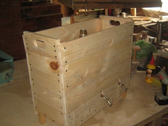
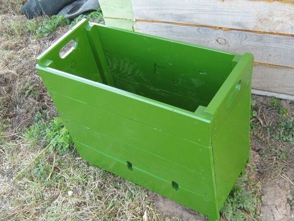
The finished box without fanaticism is sanded, primed with diluted varnish and painted in several layers with PF-115 enamel, grass green, with an intermediate sanding of the raised fibers with a fine or rubbed sandpaper. While the paint dries, you can do the manufacturing and installation of the remaining pieces of iron.
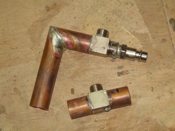
I prepared and soldered needle faucets into the surrounding reinforcement - their regular threads designed to tighten the collets, cleaned them with a wire brush, soldered with a gas torch with tin-copper solder and a special flux paste for this solder. Air Hose Connection - Quick Disconnect Standard for Spiral Pneumatic Orange Hose. Copper tubes from a water supply system with a diameter of 15 and 18 mm, it would be nice to connect them with standard parts that are offered specifically for this - couplings, angles, but only a few of their types were available - tees, couplings, plugs. I had to get out. I did the angles of 90 degrees on my own - I cut the ends of the tubes at an angle of 45 degrees on the end saw (use at least protective glasses!) And after stripping and applying flux, put them on a red brick and soldered with a burner. Do not forget to rinse from flux with warm water - acid flux. When soldering several places nearby, we proceed from the general principle - first we solder more massive parts, then less, so there is less chance that the previous soldering will decay, even if you solder with the same solder. If the diameters of the soldered parts did not substantially coincide, they dominated the required amount of copper, previously well-stripped wire, with a diameter of about 0.4 ... 0.5 mm. I dismantled the faucets before soldering as much as possible so as not to heat the plastic twist and rubber gaskets. Do not forget to try on the pipes more often at the duty station, so that, due to the absent-mindedness, as Russian rasta say, “not to mess up the sides."
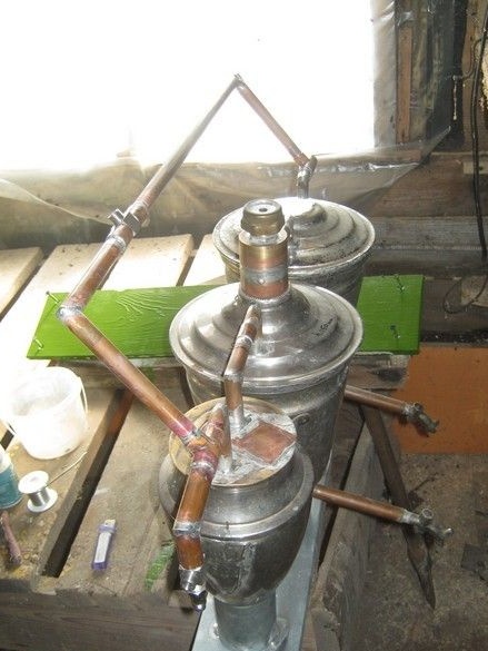
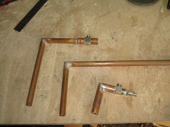
Finally, solder the prepared using the available tees. Also, the gaps are compensated by wire winding. Bypass at or slightly above the filler neck, its tap should be peeping out of the sand bed. Its tube is slightly inclined to the vertical axis, so as not to block access to the filler neck.
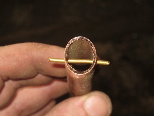
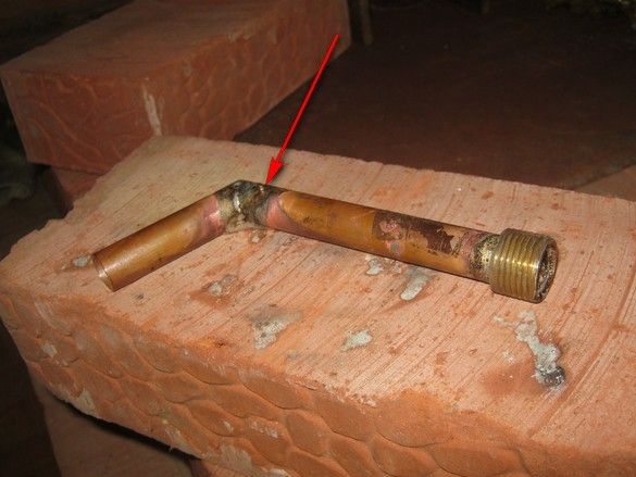
A place is arranged in the outlet pipe for the flame arrester, which prevents the ingress of flame from the “back strike” into the device. Flame arresters of this kind are required to be installed - in the vessels a ready-made mixture of fuel with an oxidizing agent and the penetration of the flame inside is fraught with serious consequences. Fortunately, the burning rate of gasoline vapors is relatively low and the copper “muddle” in the pipe is a guaranteed measure to suppress the flame. She will be filled with volume in the outlet pipe from the threaded part to the corner. So that the wire stuffing does not crawl out of its intended place, a transverse stop is soldered to turn the tube - a piece of thick brass wire. A 0.5-inch thread is soldered to the outlet end of the pipe from the water fittings - a brass “clown” from the set of the bath mixer. The non-standard angle is made similarly to the previous ones for reasons of convenience - when placing the carburetor in the lower left, under the table, the output hose will bend less.
A mandatory step is a leak test. In fully assembled vessels with fittings, it is quite simple - plug the outlet pipe with a standard plumbing plug, grease cork taps, cut out an elastic band for the filler plug. It remains to connect the compressor to the input of the device and, after pumping up several atmospheres, walk along the seams with soapy foam. Mark the places of air leakage and solder after washing and drying. Similarly check the result.
It was here with my device that an accident happened - when pumping about four atmospheres, a shell was torn off on the bubbler cover. Perhaps there was a slight defect in the factory stamping of the lid - a crack in the place of strong bending. Perhaps due to the absence or insufficient annealing before stamping. On it, a crack, the lid came off. At the same time, the tank “opened”, tearing one of the tubes to a neighbor, and slightly bent the base. Several attempts were made to repair, but it was impossible to restore the device accurately, and most importantly, reliably, without significant dismantling. The device is set aside for less critical than fuel vessel use.
The result of the accident, in general, was excessive confidence and significantly less pressure was enough to check the tightness with soap bubbles. During the normal operation of the device, the pressure inside the vessels does not exceed atmospheric pressure, and by taking known measures to protect against the “reverse flame strike” (copper nets, “muddle”), the vessels can be made of very thin materials.