
In this homemade AKA KASYAN will make a universal step-down and step-up voltage converter.
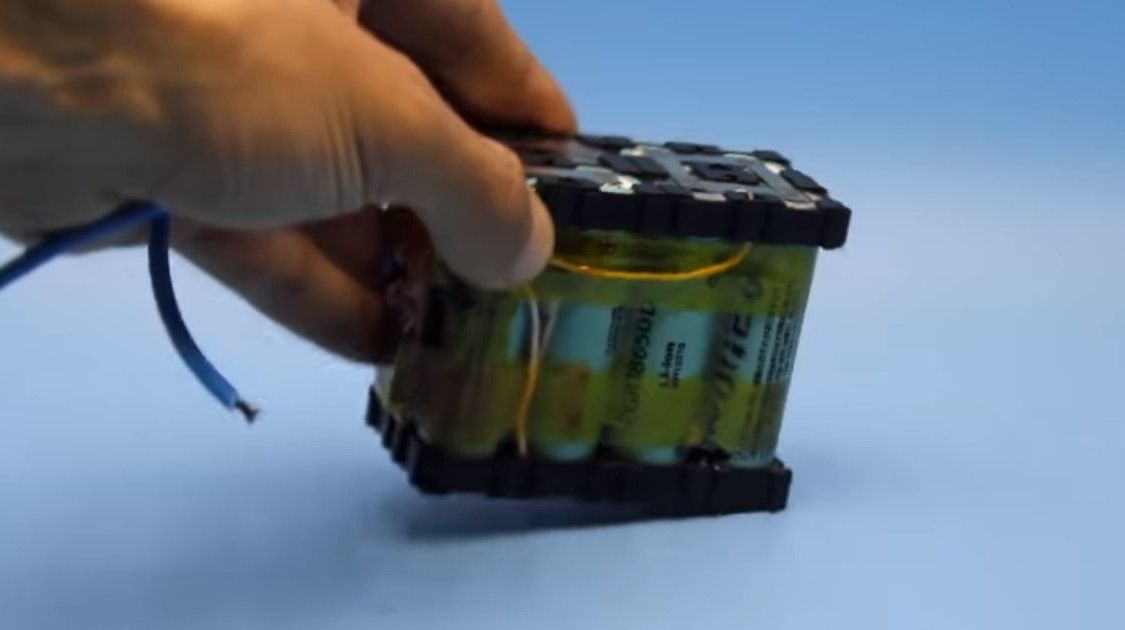
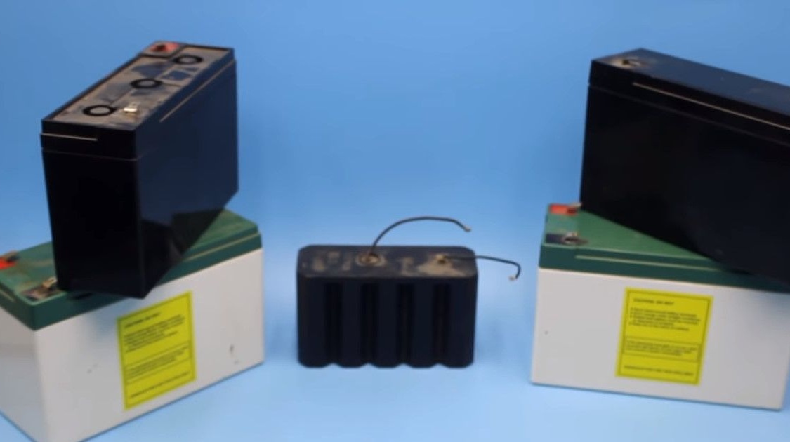
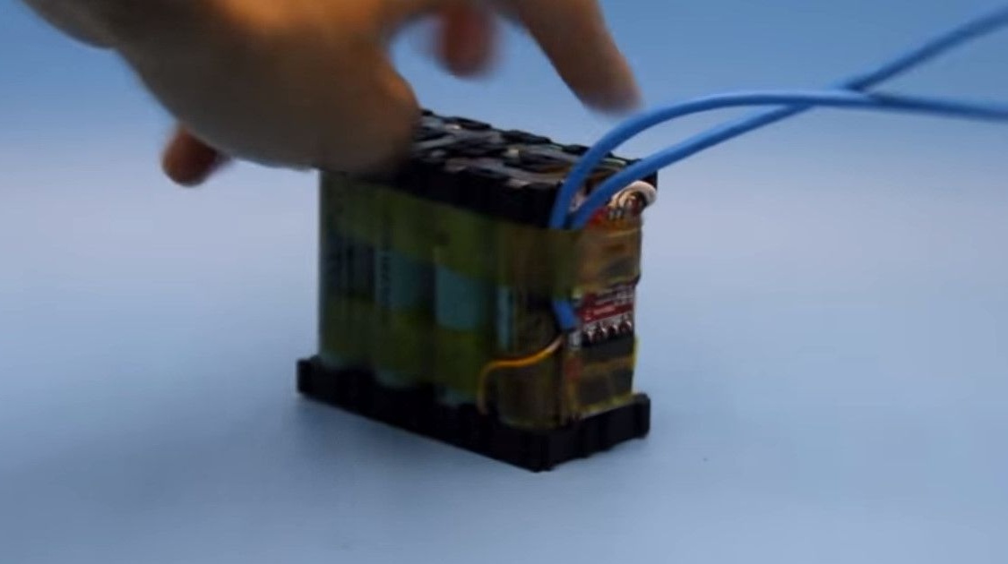
Recently, the author assembled a lithium battery. And today it will reveal the secret for what purpose he made it.
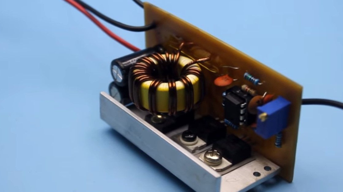
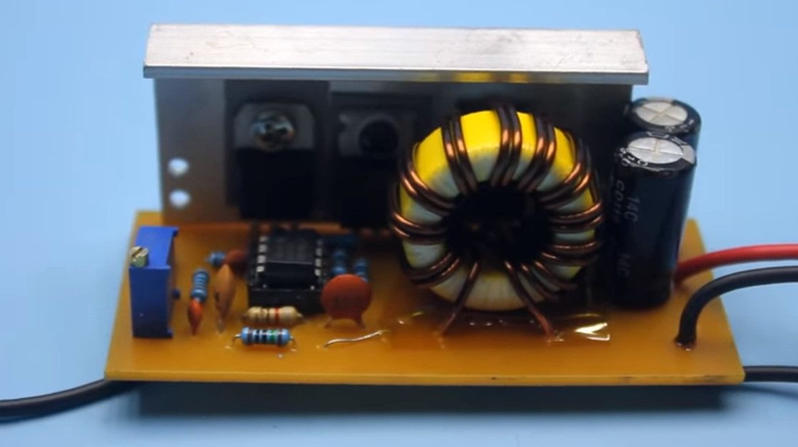
Here is a new voltage converter, its operation mode is single-cycle.
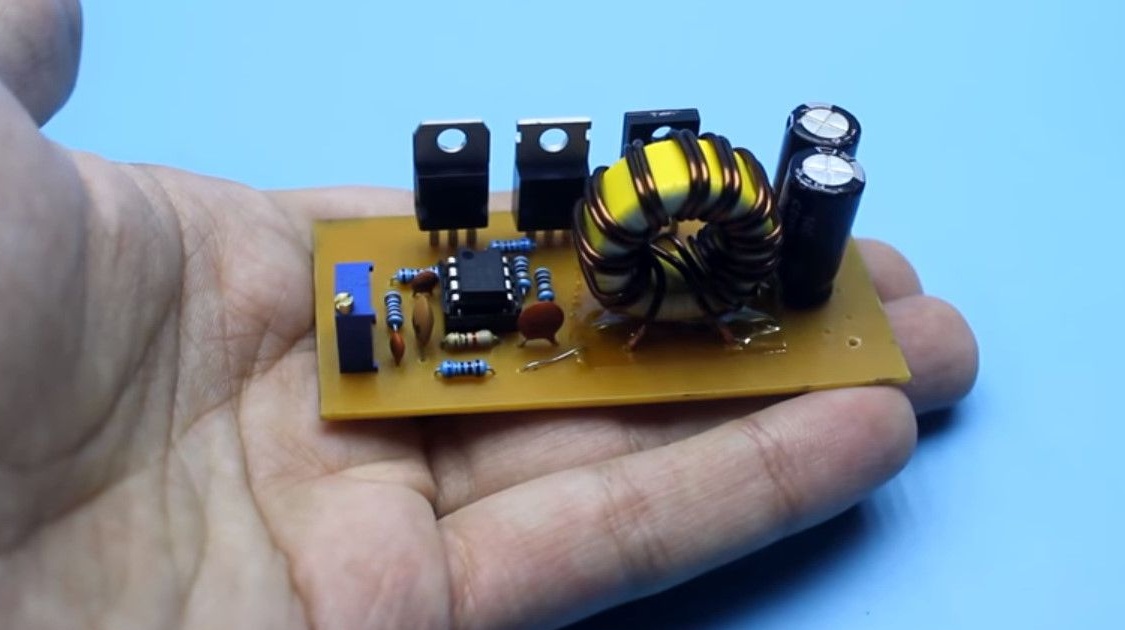
The converter has small dimensions and a sufficiently large power.
Conventional converters do one of two things. They only increase or only lower the voltage supplied to the input.
An option made by the author can both increase,
and lower the input voltage to the desired value.
The author has various regulated power supplies with which he tests assembled homemade products.
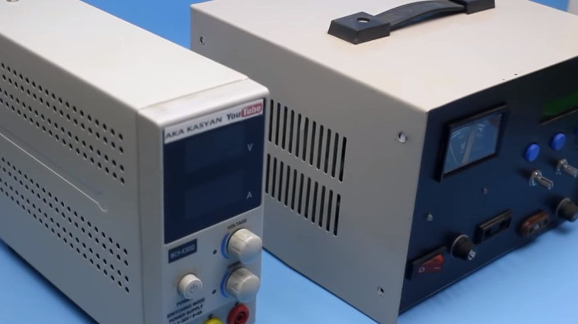
Charges batteries, and uses them for various other tasks.
Not so long ago, the idea of creating a portable power source came up.
The task was as follows: the device should be able to charge all kinds of portable gadgets.

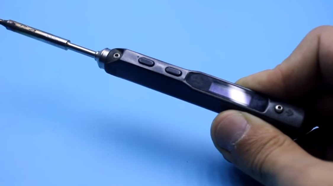
From ordinary smartphones and tablets to laptops and camcorders, I also managed to cope with the power of TS-100’s favorite soldering iron.
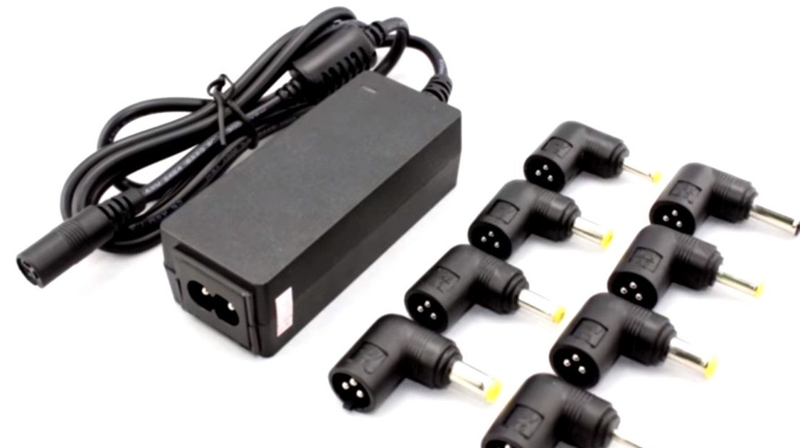
Naturally, you can simply use universal chargers with power adapters.
But all of them are powered by 220V
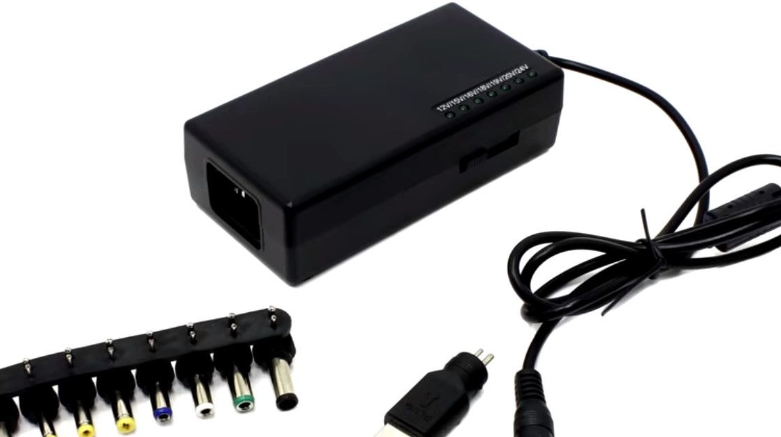
In the case of the author, a portable source of various output voltages was needed.
And the author did not find those on sale.
The supply voltage for these gadgets have a very wide range.
For example, smartphones need only 5 V, laptops 18, some even 24 V.
The battery made by the author is designed for an output voltage of 14.8 V.
Therefore, a converter is needed that can both increase and decrease the initial voltage.
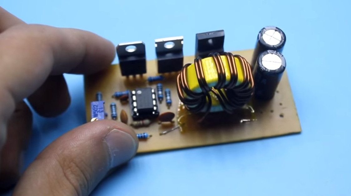
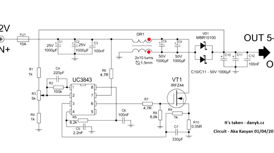
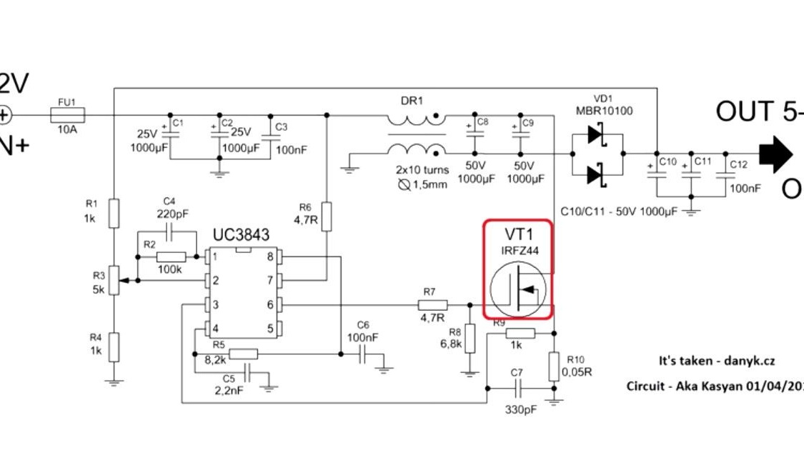
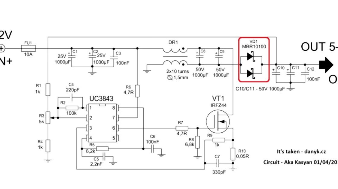
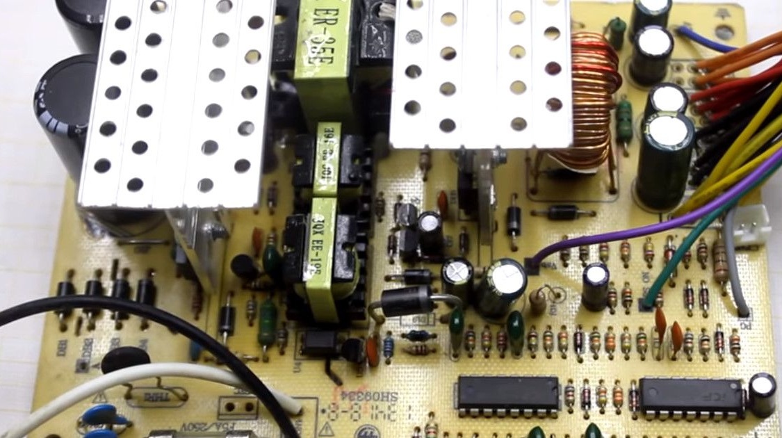
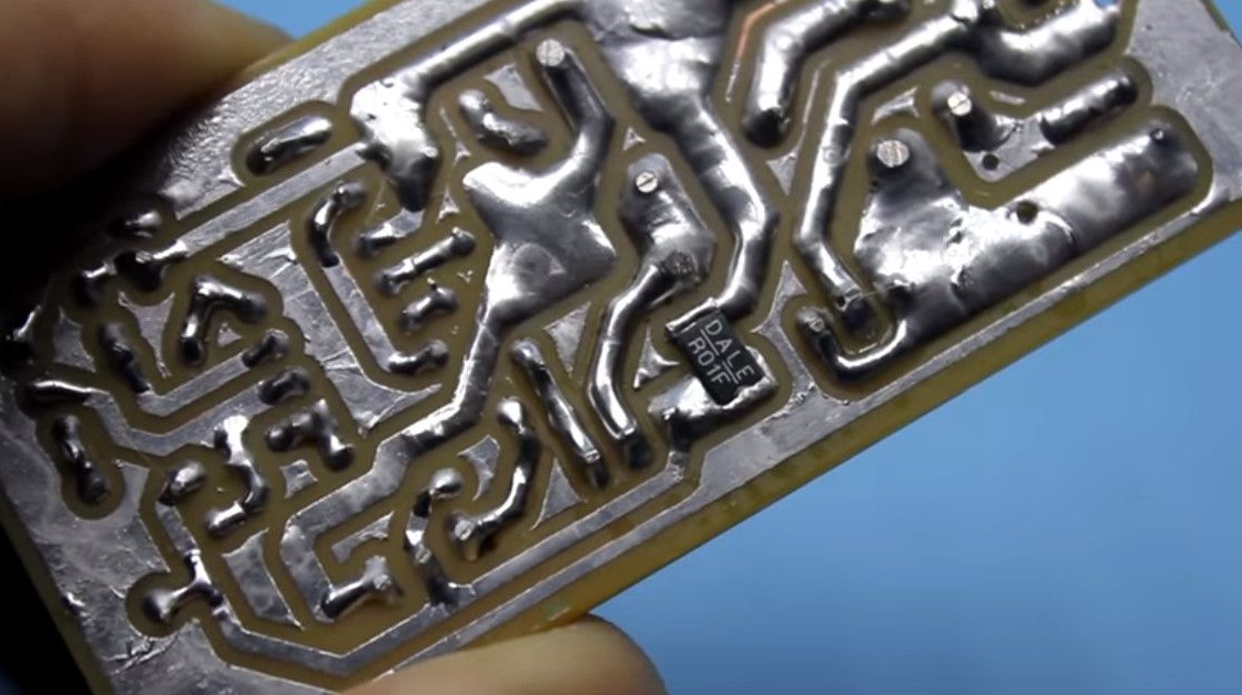
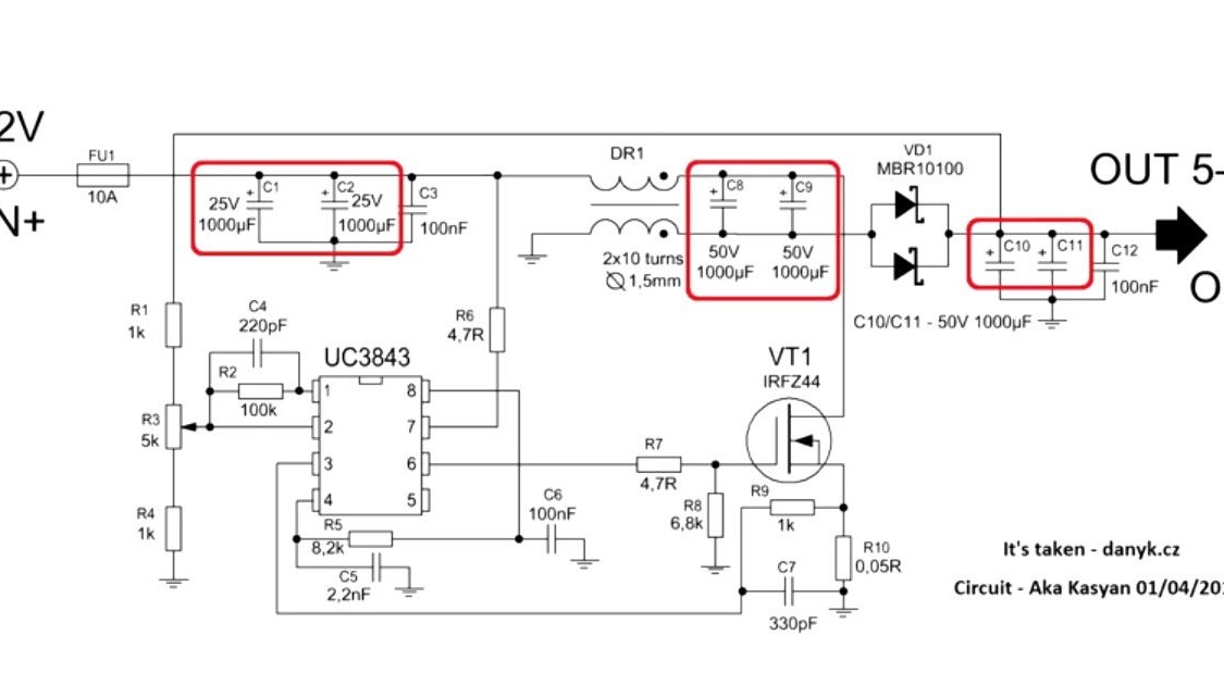
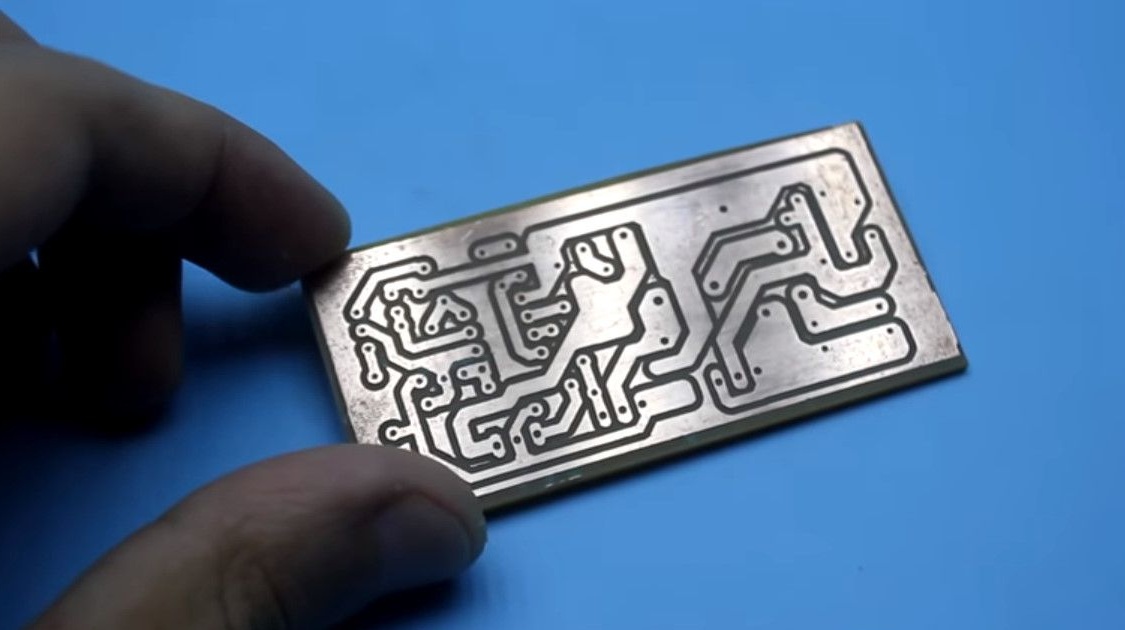
Please note that some values of the components indicated on the diagram differ from those installed on the board.
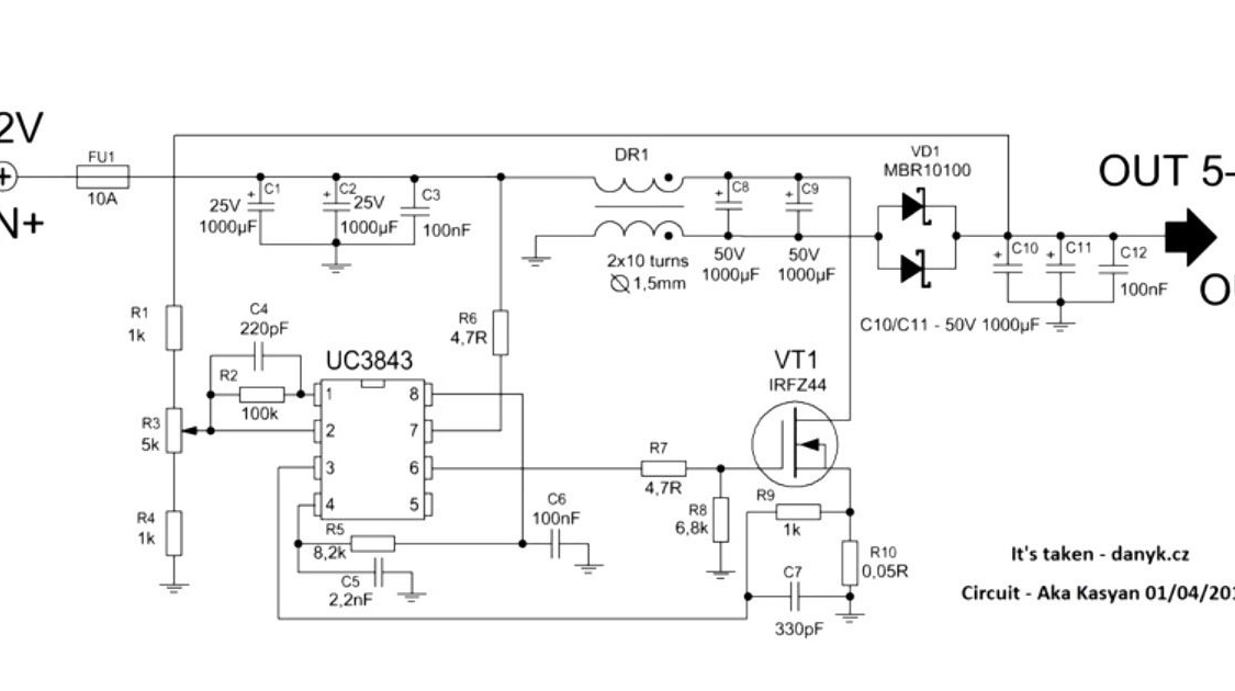
These are capacitors.
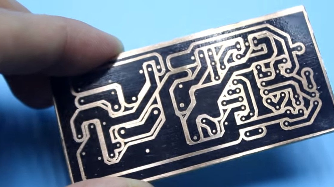
The reference values are indicated on the diagram, and the author made a board to solve his problems.
Firstly, I was interested in compactness.
Secondly, the author's power converter allows you to safely create an output current of 3 amperes.

AKA KASYAN and more is not necessary.
This is due to the fact that the capacitance of the applied storage capacitors is small, but the circuit is capable of delivering an output current of up to 5 A.
Therefore, the scheme is universal. The parameters depend on the capacitance of the capacitors, the parameters of the inductor, the diode rectifier and the characteristics of the field key.
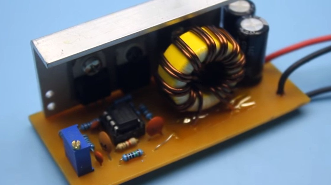
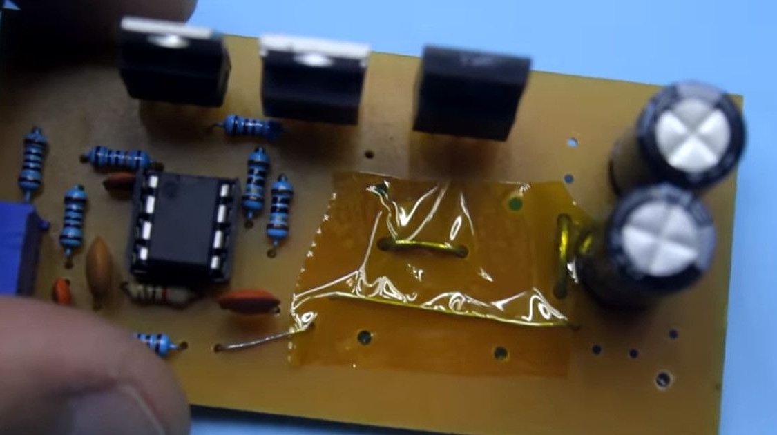
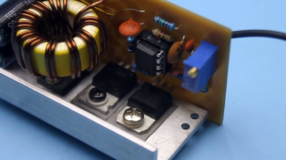
Let's say a few words about the scheme. It is a single-cycle converter based on the UC3843 PWM controller.
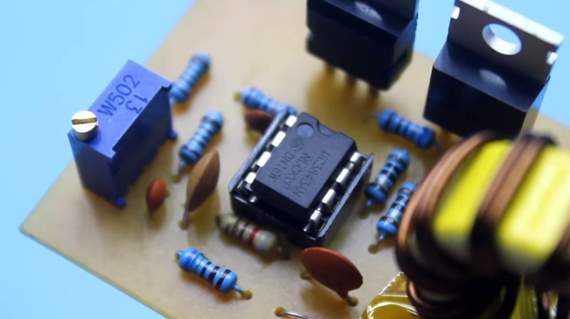
Since the voltage from the battery is slightly higher than the regular power supply of the microcircuit, a 12V 7812 stabilizer was added to the circuit to power the PWM controller.
In the above diagram, this stabilizer was not indicated.
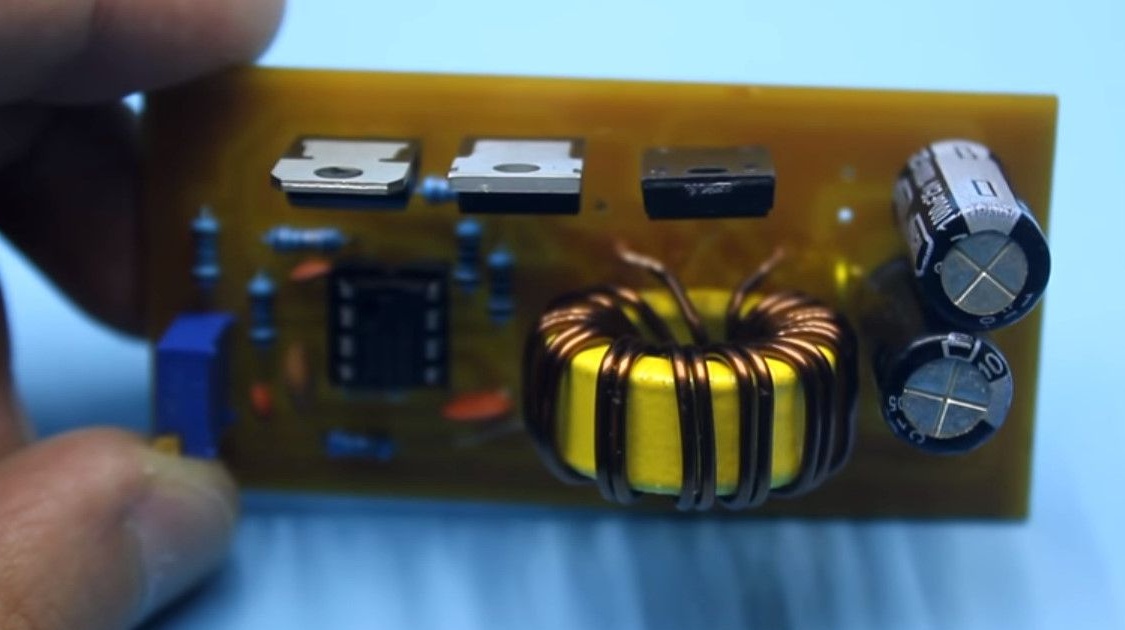
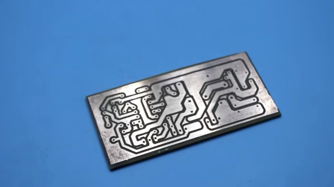
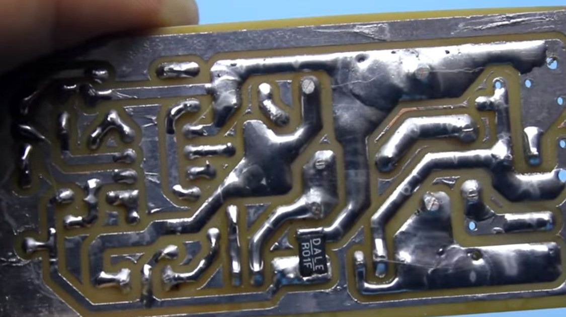
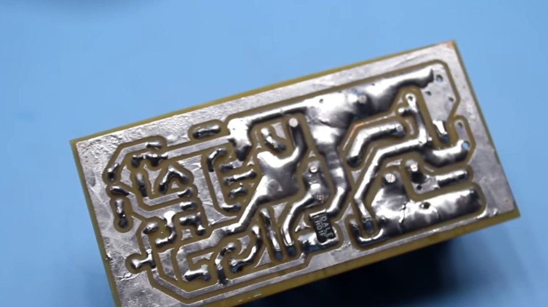
Assembly. About jumpers installed on the mounting side of the board.
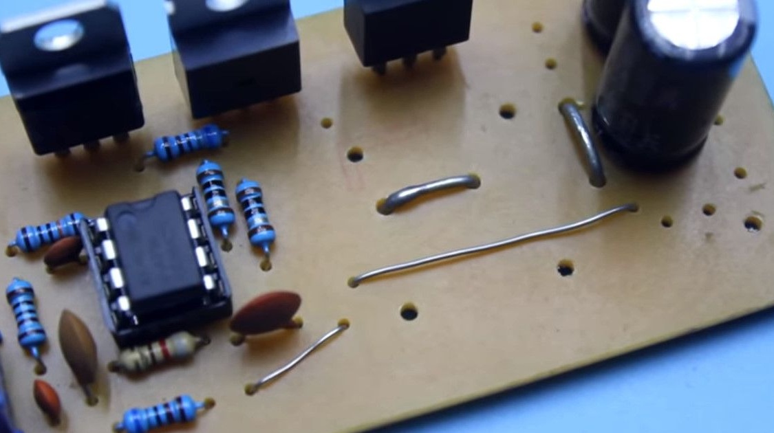
There are four of these jumpers, and two of them are power. Their diameter must be at least a millimeter!
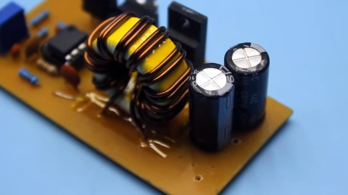
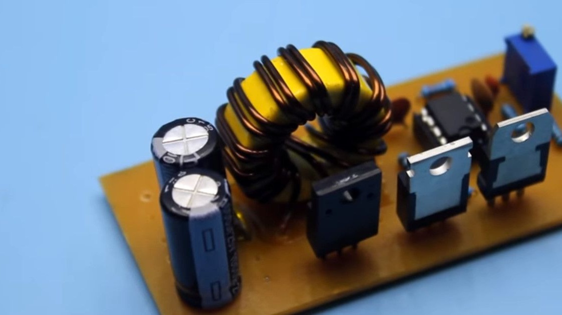
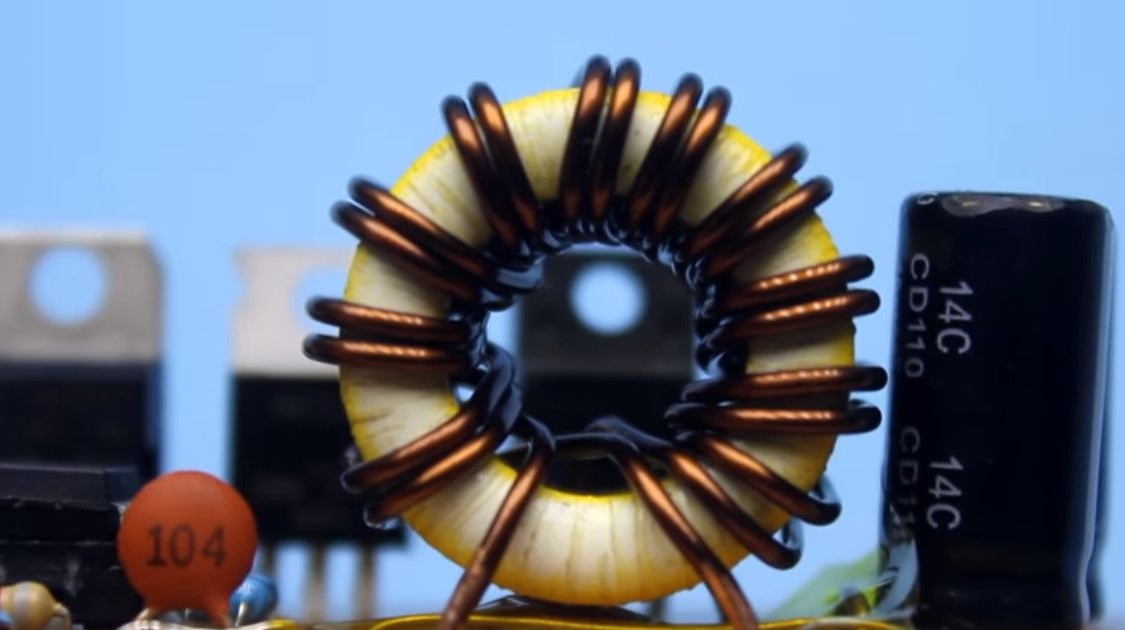
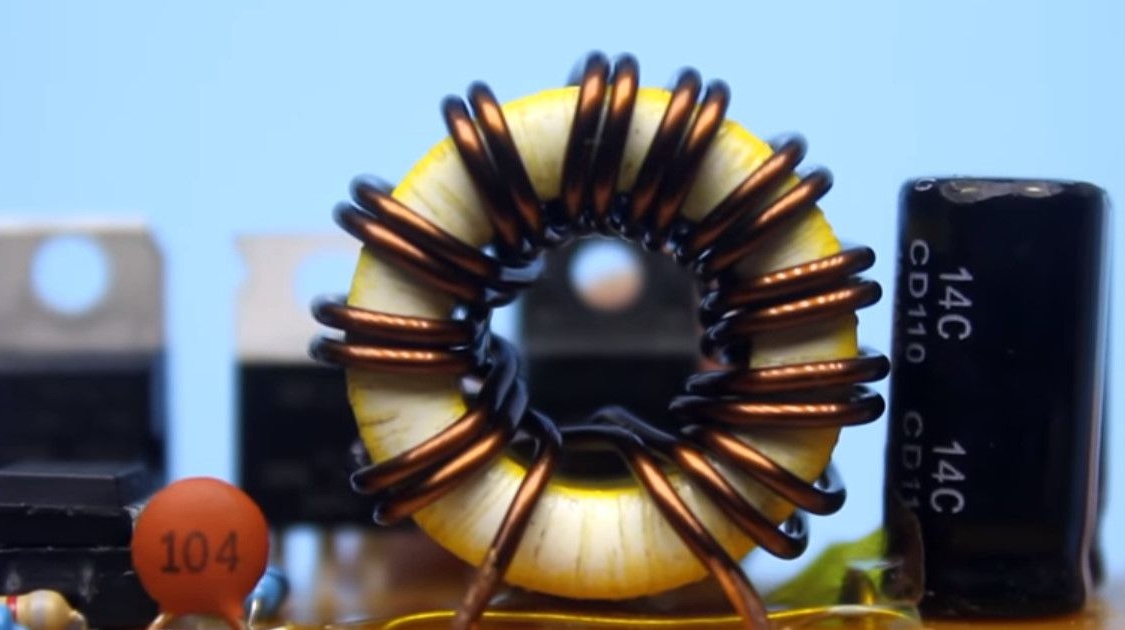
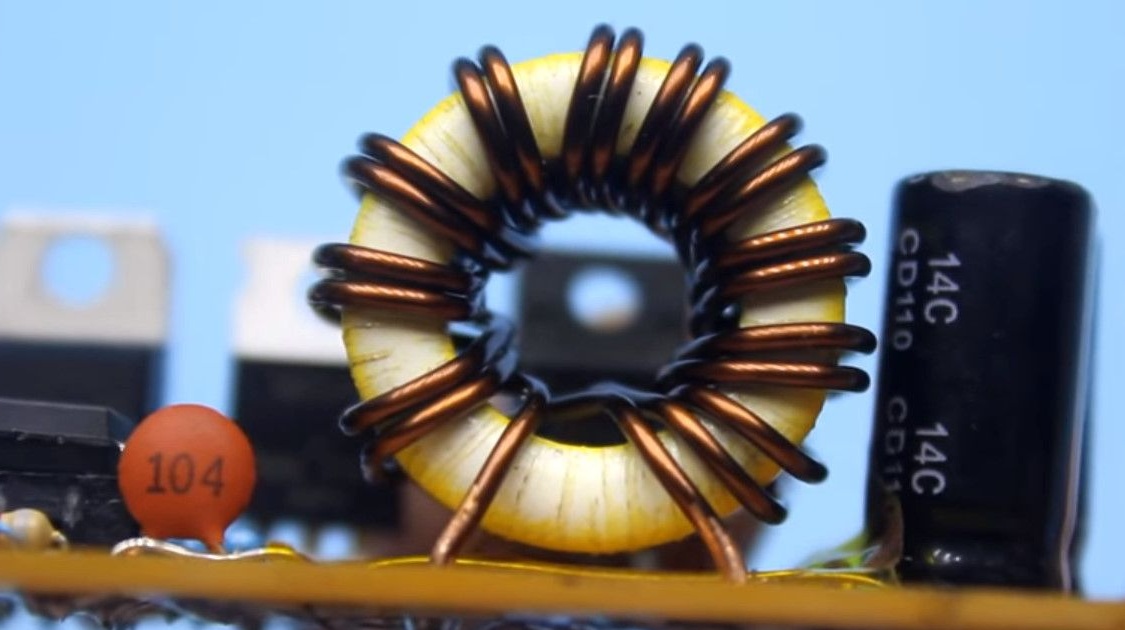
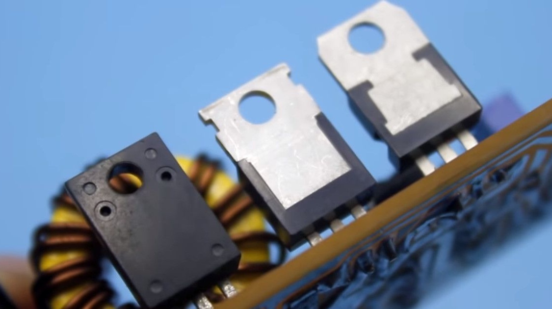
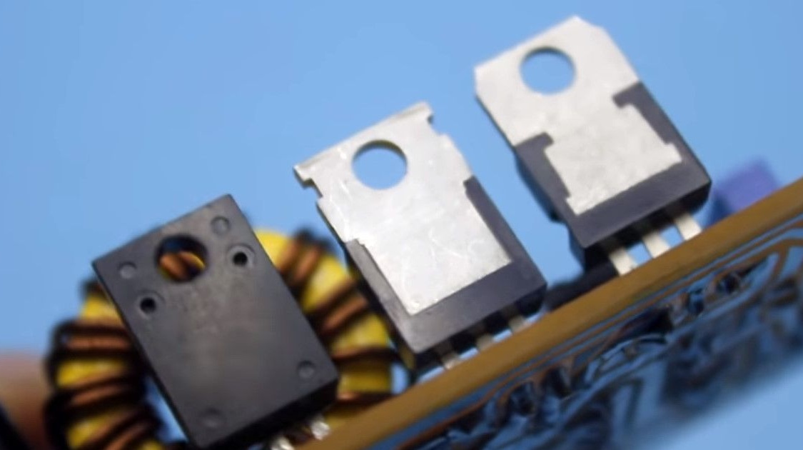
A transformer, or rather a choke, is wound on a yellow ring of powdered iron.

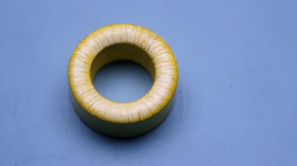
Such rings can be found in the output filters of computer power supplies.
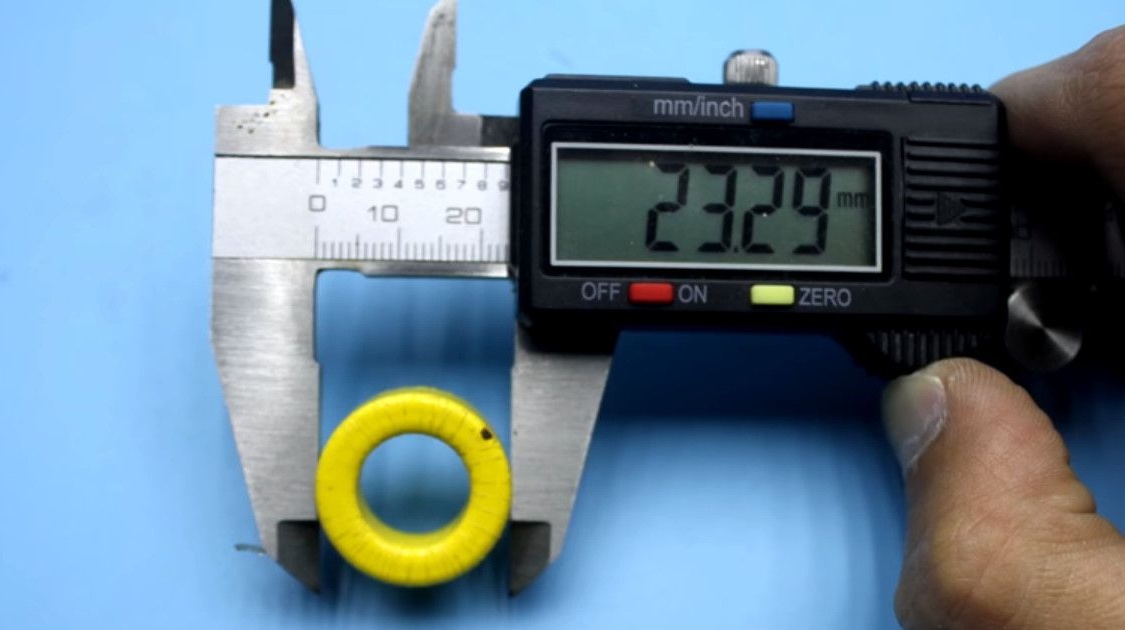
Dimensions of the applied core.
The outer diameter is 23.29mm.
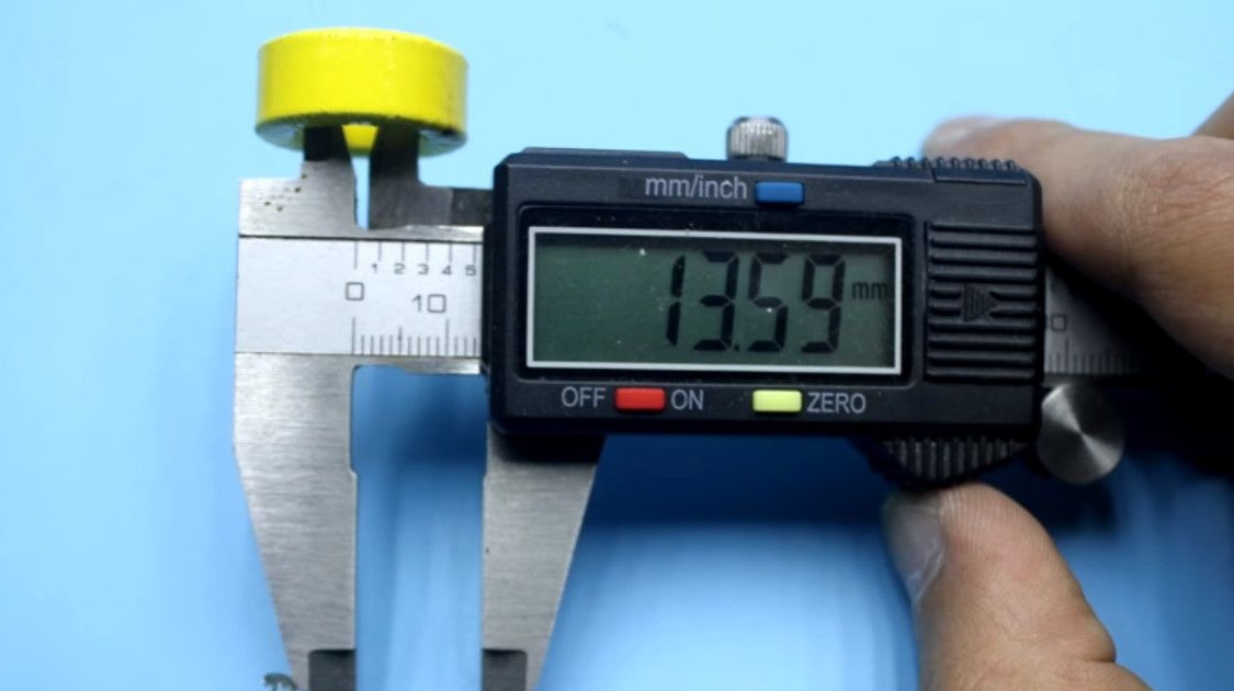
The inner diameter is 13.59mm.
Thickness 10.33mm.
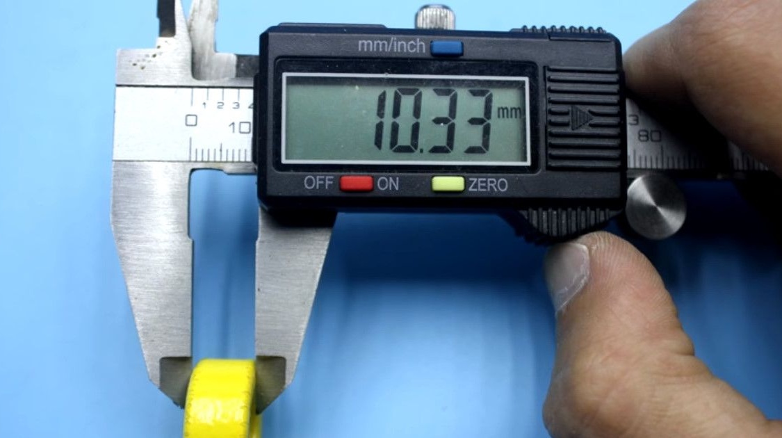
Most likely, the thickness of the insulation winding is 0.3 mm.
The inductor consists of two equivalent windings.
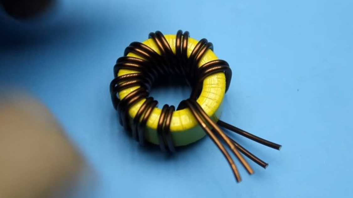
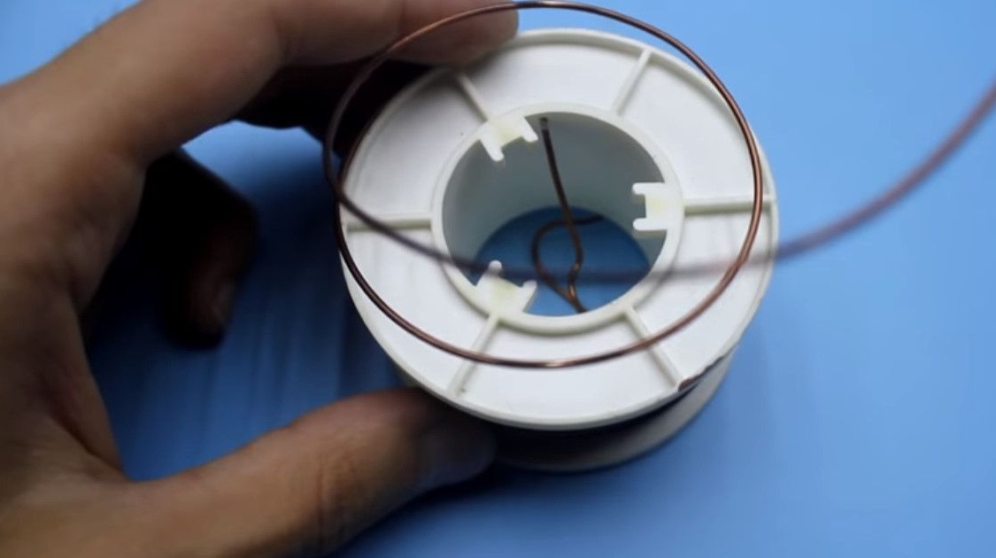
Both windings are wound with 1.2 mm diameter copper wire.
The author recommends using a wire with a diameter slightly larger, 1.5-2.0 mm.
There are ten turns in the winding, both wires are wound at once, in one direction.
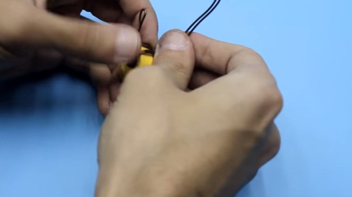
Before installing the throttle jumpers we seal with nylon tape.
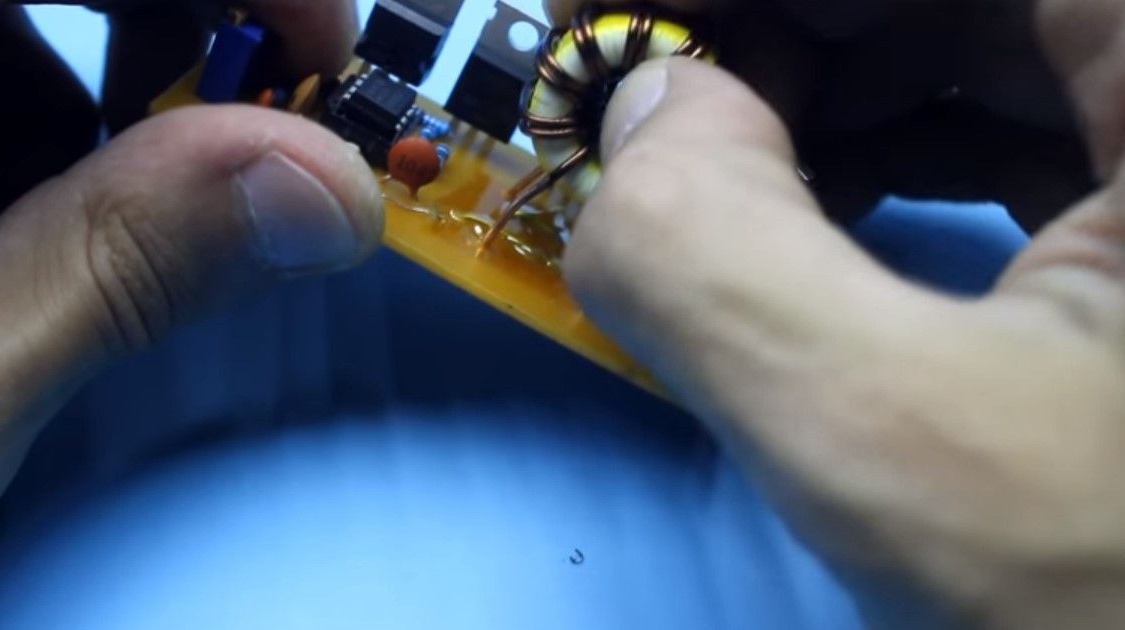
The operation of the circuit consists in the correct installation of the throttle.
It is necessary to solder the winding leads correctly.
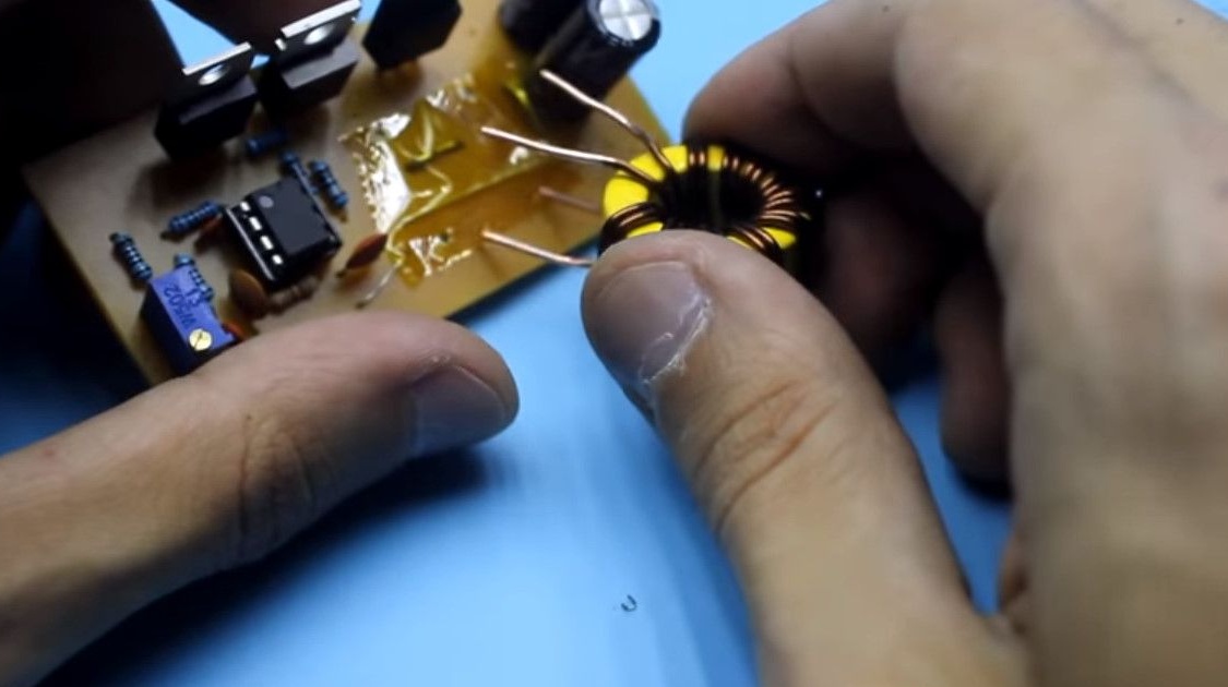
Just install the throttle as shown in the photo.

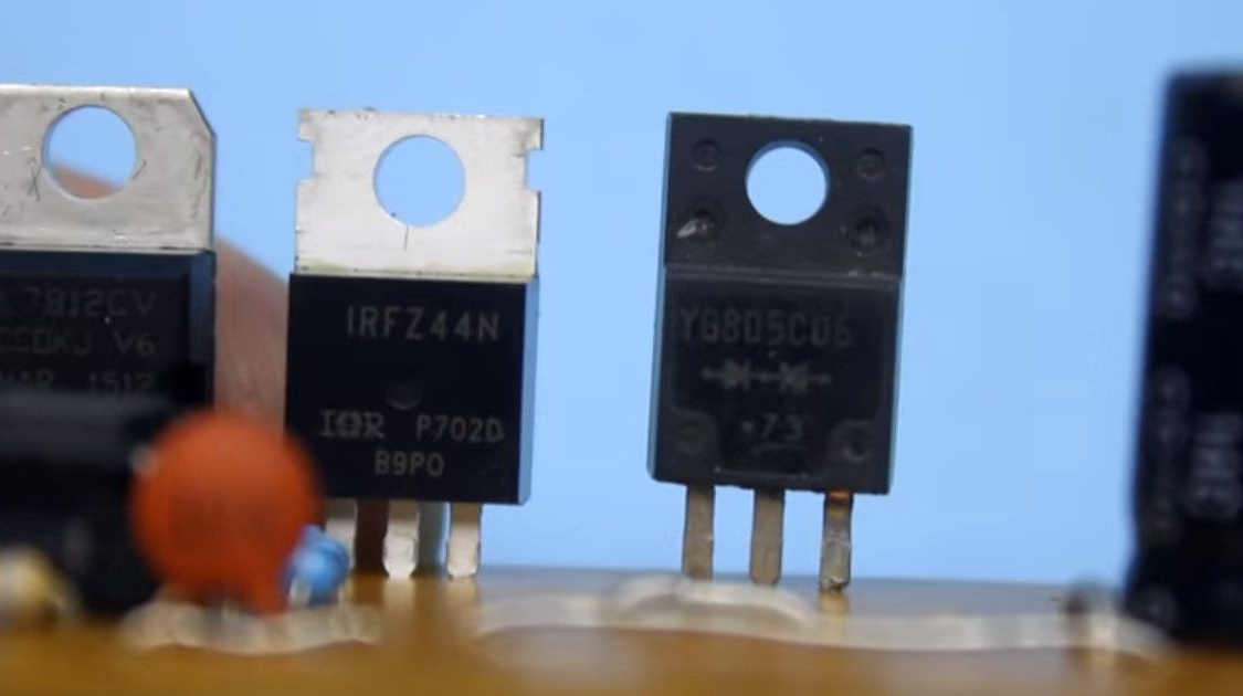
Power N-channel field effect transistor, suitable for almost any low-voltage.
The transistor current is not lower than 30A.
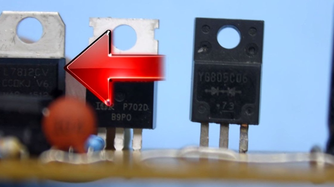
The author used a transistor IRFZ44N.
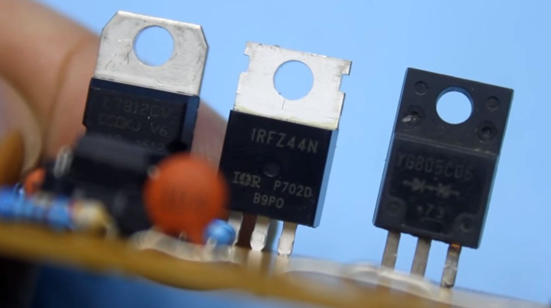
The output rectifier is a YG805C dual diode in a TO220 package.
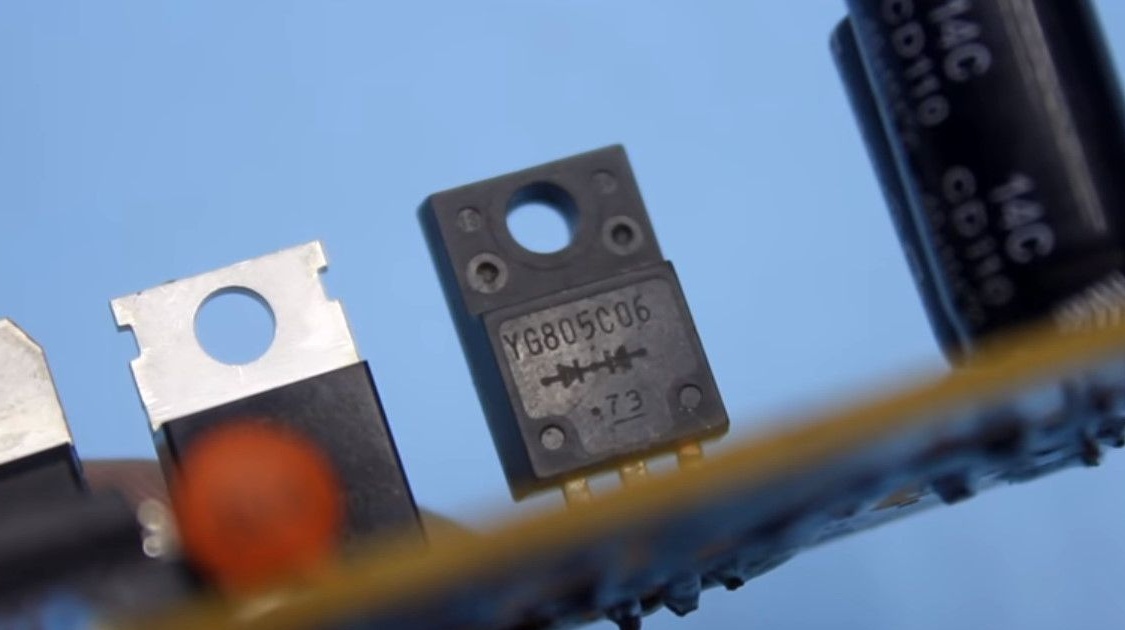
It is important to use Schottky diodes, since they give a minimum voltage drop (0.3V vs. 0.7) at the junction, this affects losses and heating. They are also easy to find in the notorious computer power supplies.
In blocks, they stand in the output rectifier.
In one case - two diodes, which in the author’s circuit are parallelized to increase the passing current.
The converter is stabilized, there is feedback.
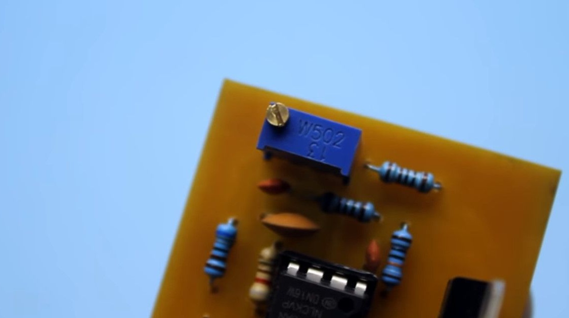
The output voltage sets the resistor R3
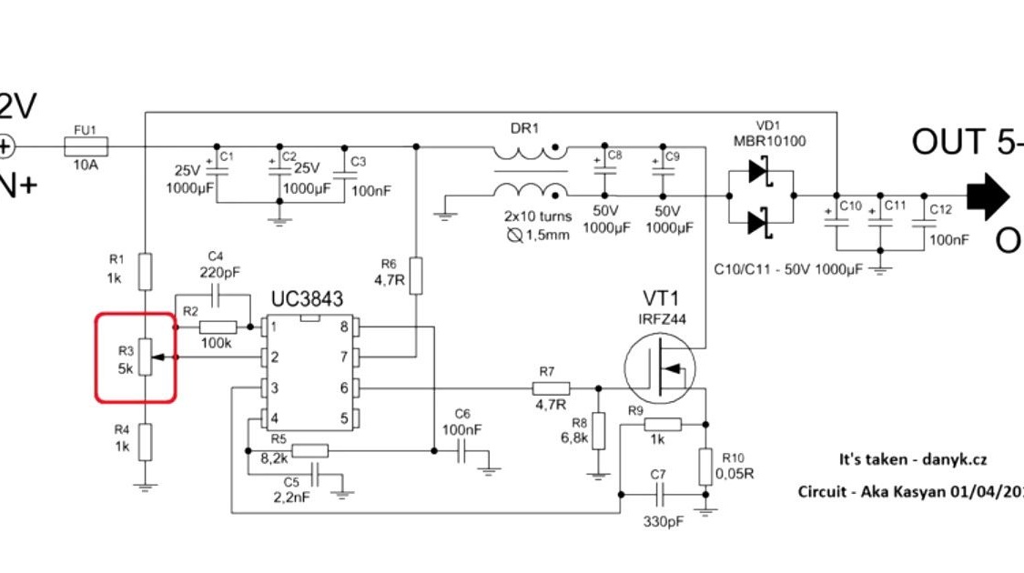
It can be replaced with a remote variable resistor for easy operation.
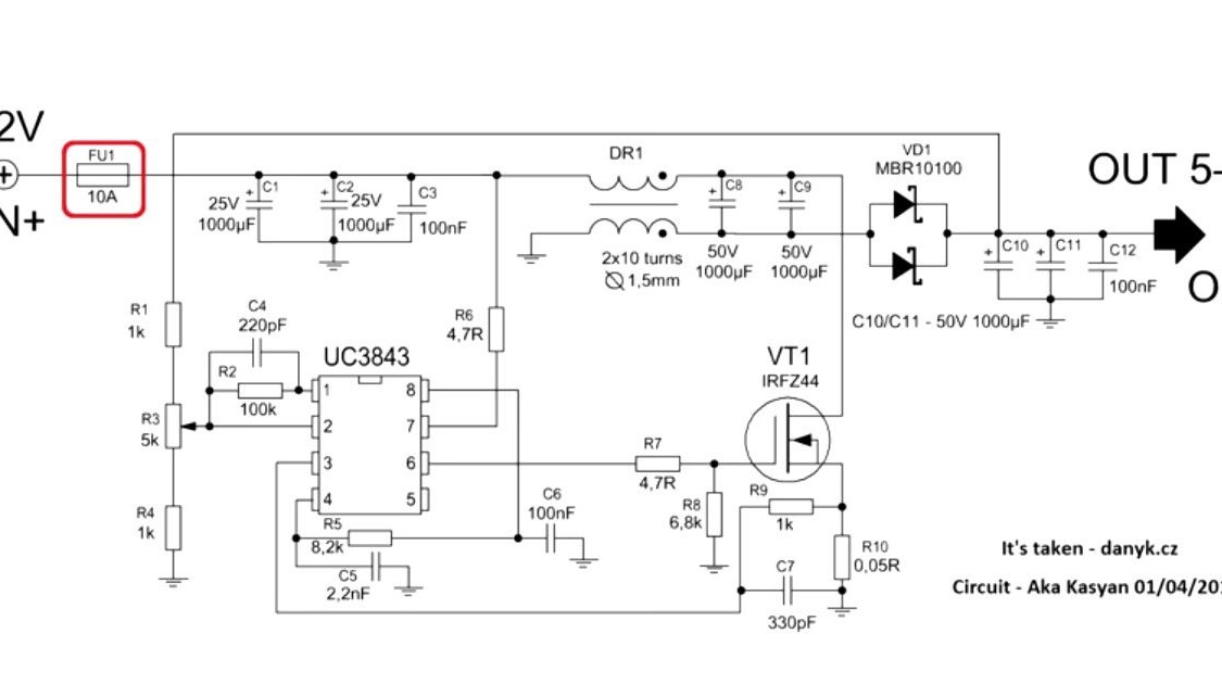
The converter is also equipped with short circuit protection. A resistor R10 is used as a current sensor.
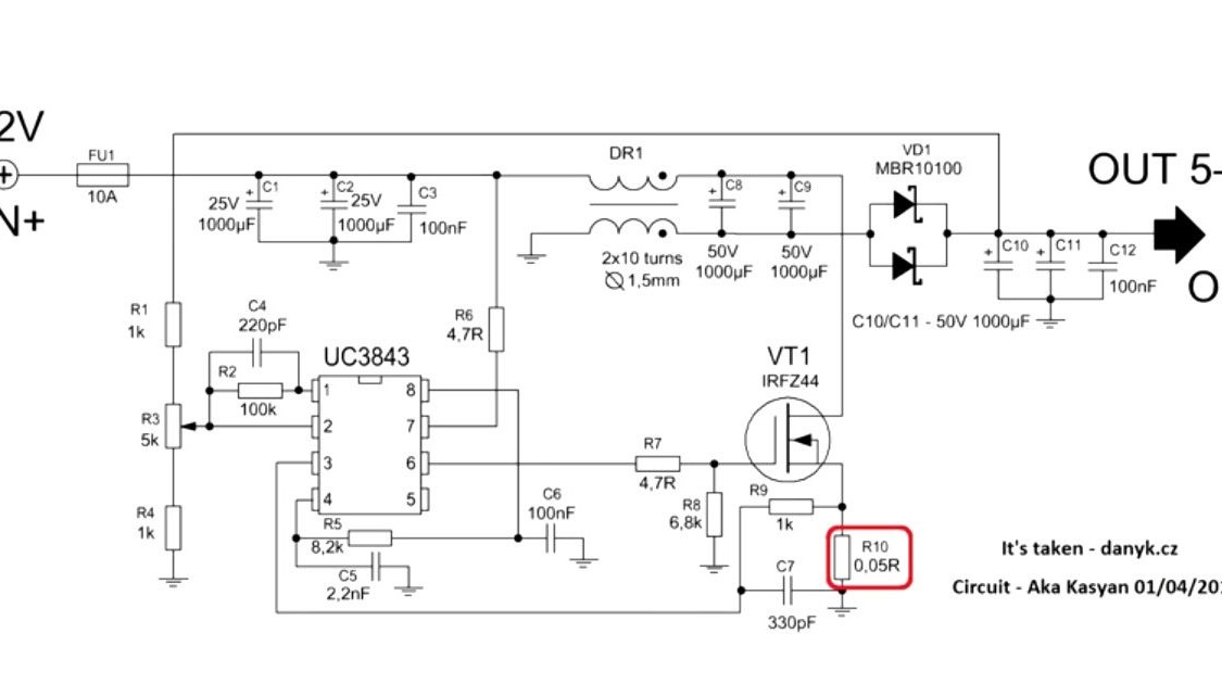
This is a low-impedance shunt, and the higher its resistance, the lower the trip current of the protection. Installed SMD option, on the side of the tracks.
If protection against short circuit is not needed, then this node is simply excluded.
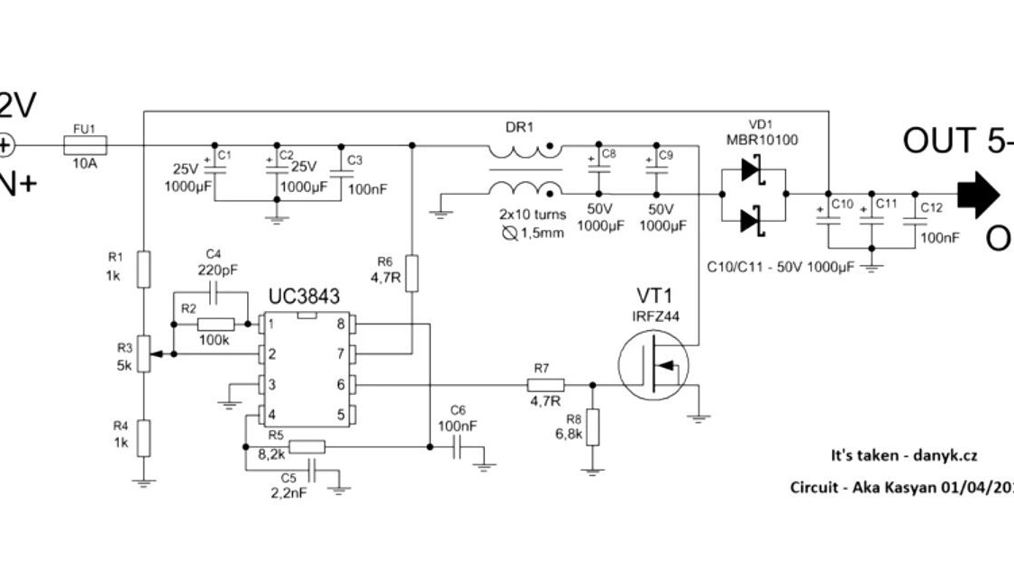
Another defense. At the input of the circuit there is a 10A fuse.
By the way, short circuit protection is already installed in the battery control board.
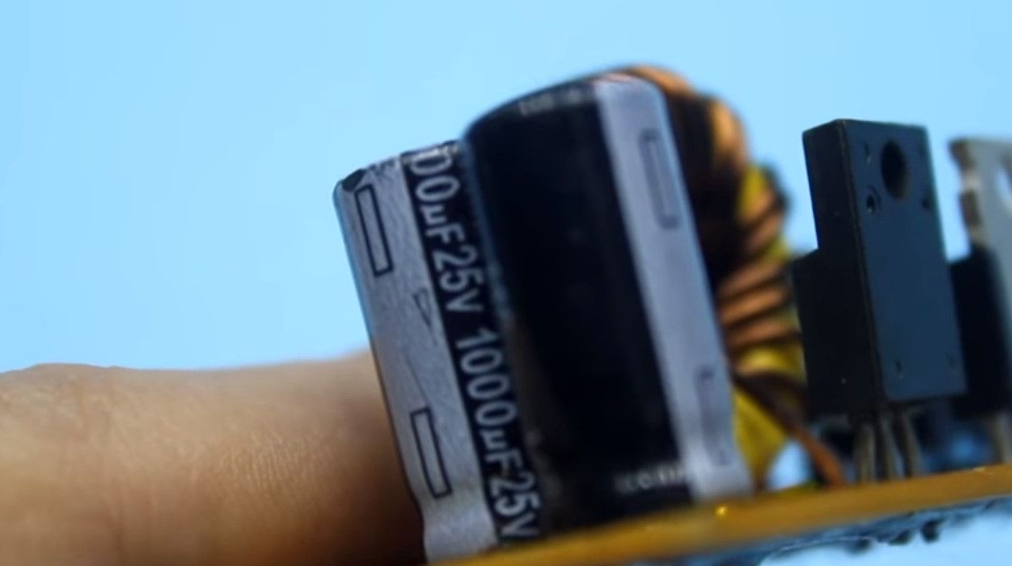
The capacitors used in the circuit are highly advisable to take with low internal resistance.
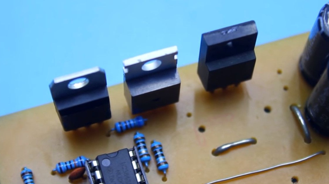
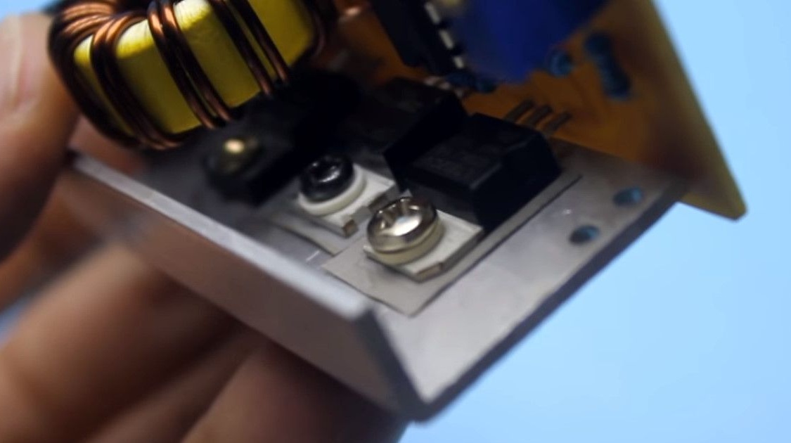
The stabilizer, field effect transistor and diode rectifier are attached to the aluminum radiator in the form of a bent plate.
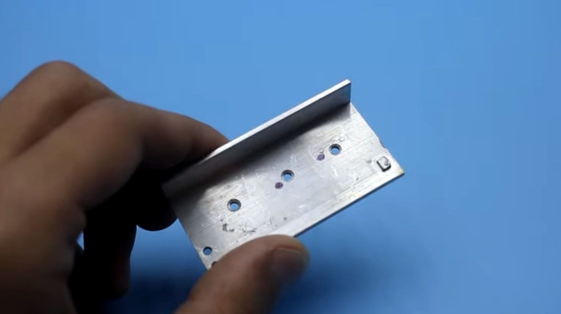
Be sure to isolate the substrates of the transistor and the stabilizer from the radiator using plastic bushings and heat-conducting insulating gaskets. Do not forget about thermal grease. And the diode installed in the circuit already has an insulated housing.
Thanks to PWM control, the efficiency of the converter is very high.
For example, the open circuit current, depending on the supply voltage, is in the range of 20mA - 40mA.
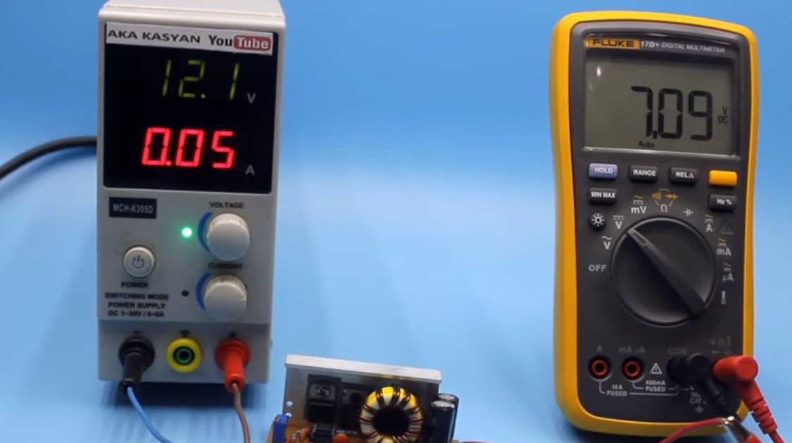
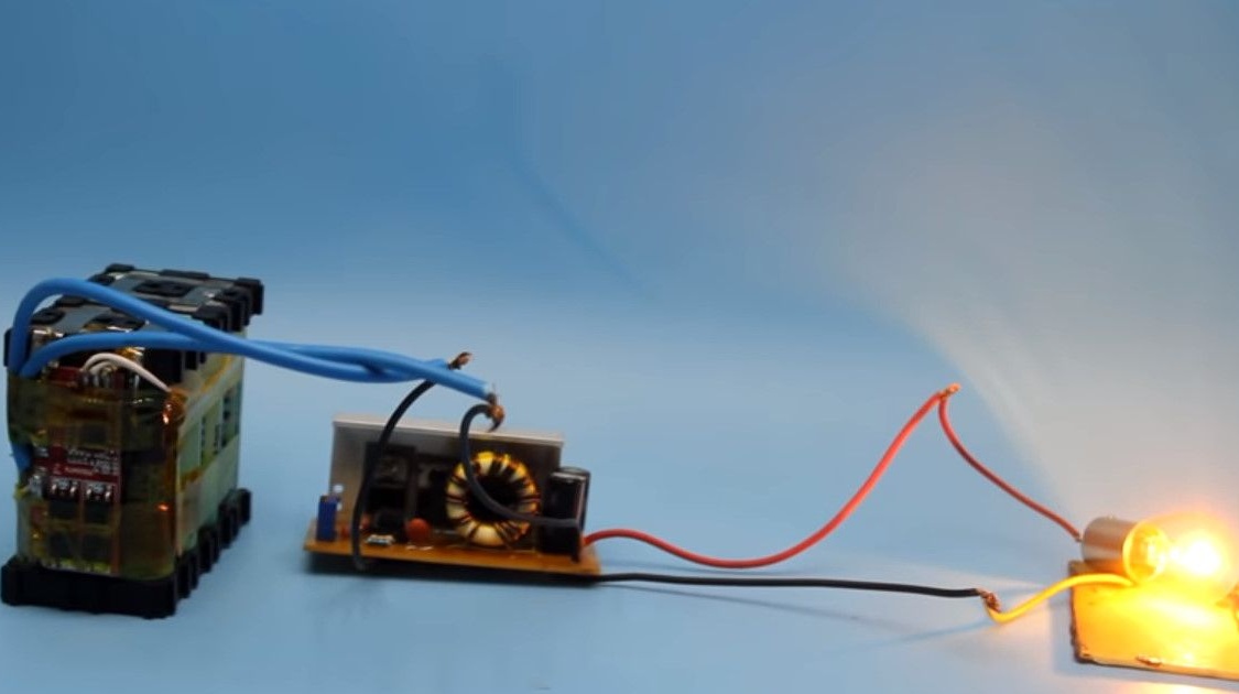
Let's start the tests.
First, check the output voltage ranges.
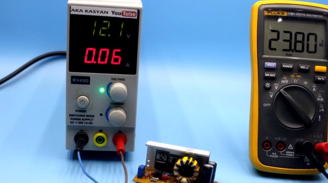
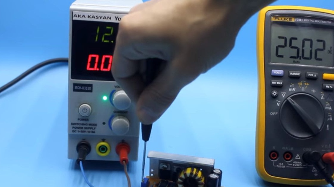
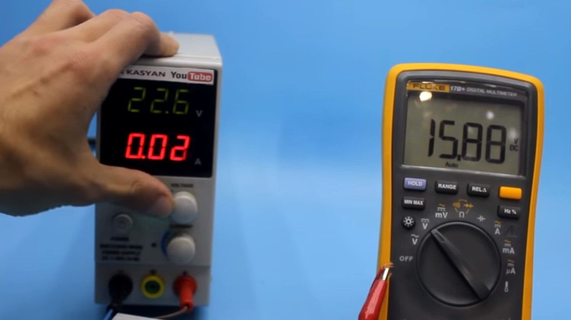
We apply 12 V to the input. The output voltage reaches twenty-five. Cannot be raised higher, output capacitors are 25 V.
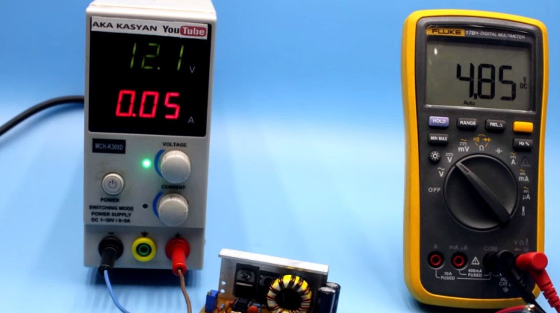
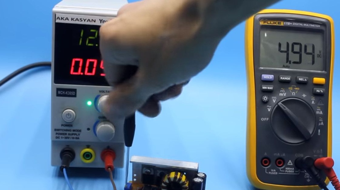
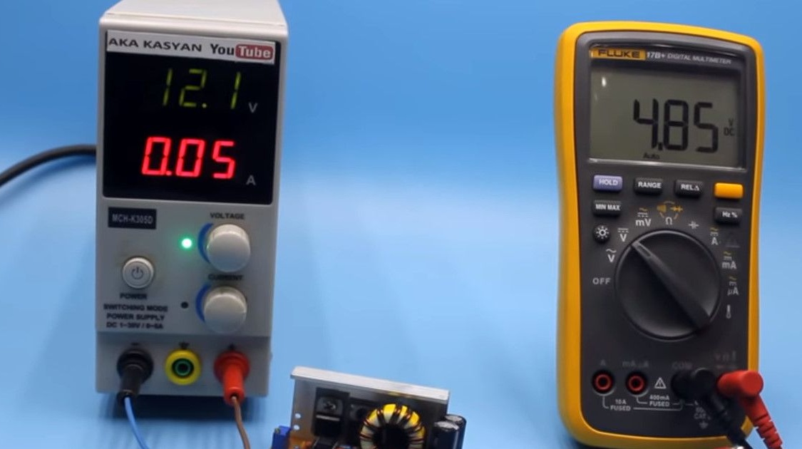
The minimum output voltage is 4.85 V. Therefore, you can charge all USB gadgets.
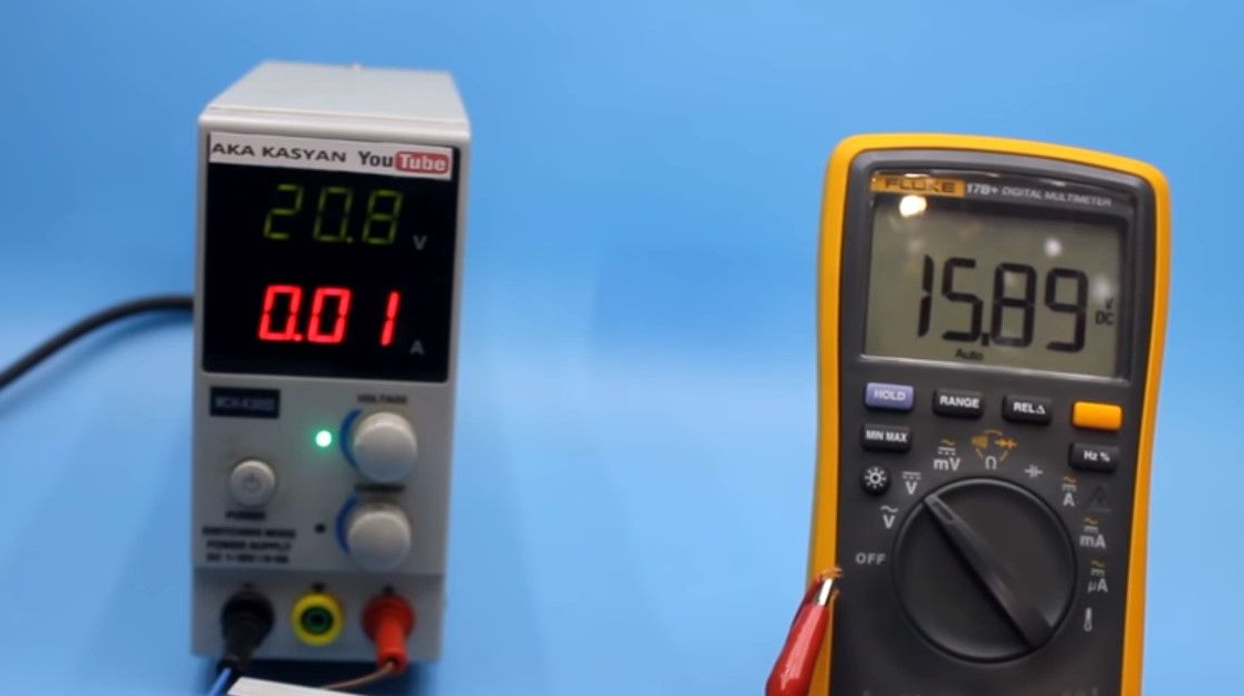
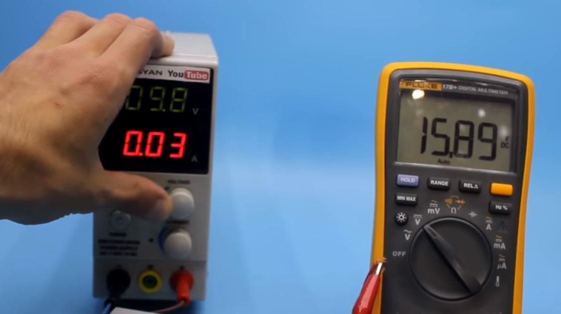
Stabilization works great! By increasing the input voltage to 22.2 V, the output is exactly within the specified limits.

With a compact size, the stabilizer gives an output current of 2.5 - 3 A with virtually no subsidence of the output voltage.
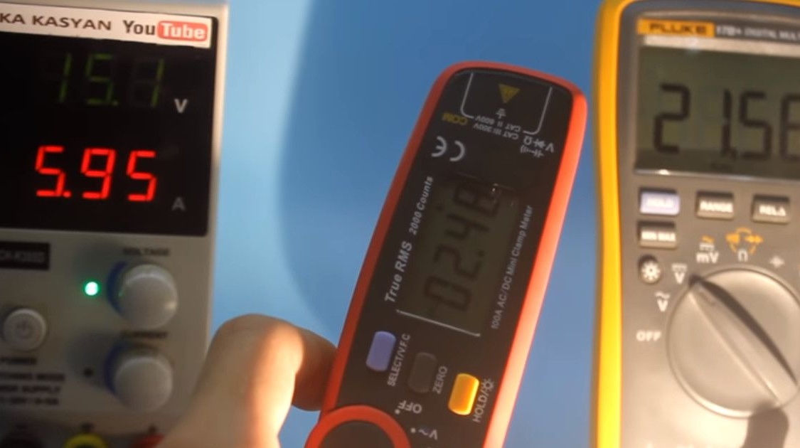
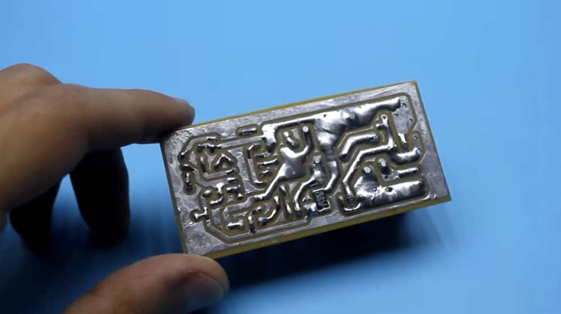
It is important to solder the wide power paths of the circuit board. For large currents flow there.
Many thanks to AKA KASYAN for the work done!
Links to components are in the description of the original video.
Link to the original video - under the text is the "source" button.