
If you are looking for a simple and reliable linear power supply circuit, then this article is for you. Here you will find complete assembly instructions, as well as setting up this power supply. The author of this homemade product is Roman (YouTube channel "Open Frime TV").
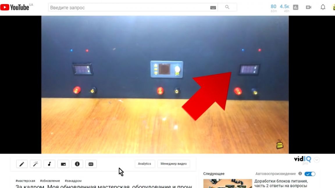
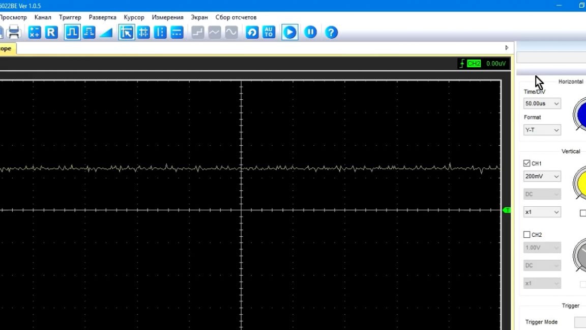
First, a little background. Most recently, the author reworked his workplace and wanted to install a linear block as the third power supply, since sometimes he has to collect circuits that do not tolerate voltage ripples. And as we know, then the linear block at the output, the ripple voltage is almost completely absent.
Up to this point, the linear blocks of the author were not very interested, and somehow he did not particularly delve into this topic. When the idea came to build such a block, Roman immediately opened the beloved and well-known YouTube video hosting service to everyone. As a result, after a lengthy search, the author was able to identify 2 schemes for himself. The author of the first is AKA KASYAN (author of the YouTube channel of the same name), and the second scheme is built on the operatives.
But since the operatives can work at voltages up to 32V, the output voltage, respectively, could not exceed this limit, which means this circuit disappears.
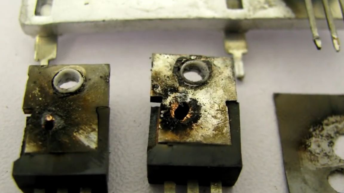
Okay, you can assemble a circuit from Kasyan, but here we were disappointed. This scheme is afraid of static. This was manifested by the explosion of transistors if you take up the output contacts.
That has been several times. And then the author decided to leave this scheme alone. You will say that the Internet is full of linear power supply circuits.
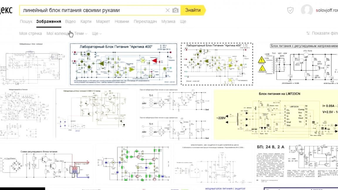
Yes, undoubtedly this is so, but only these two schemes mentioned above had normally divorced seals that could be easily downloaded. Everything else, either without seals, or assembled by hinged installation. And we (radio amateurs) are accustomed to the fact that everything is served on a silver platter.
And when all the options were exhausted, the author remembered that about 3 years ago he was already assembling a linear block, which, by the way, also worked perfectly. A scheme of three years ago was found.

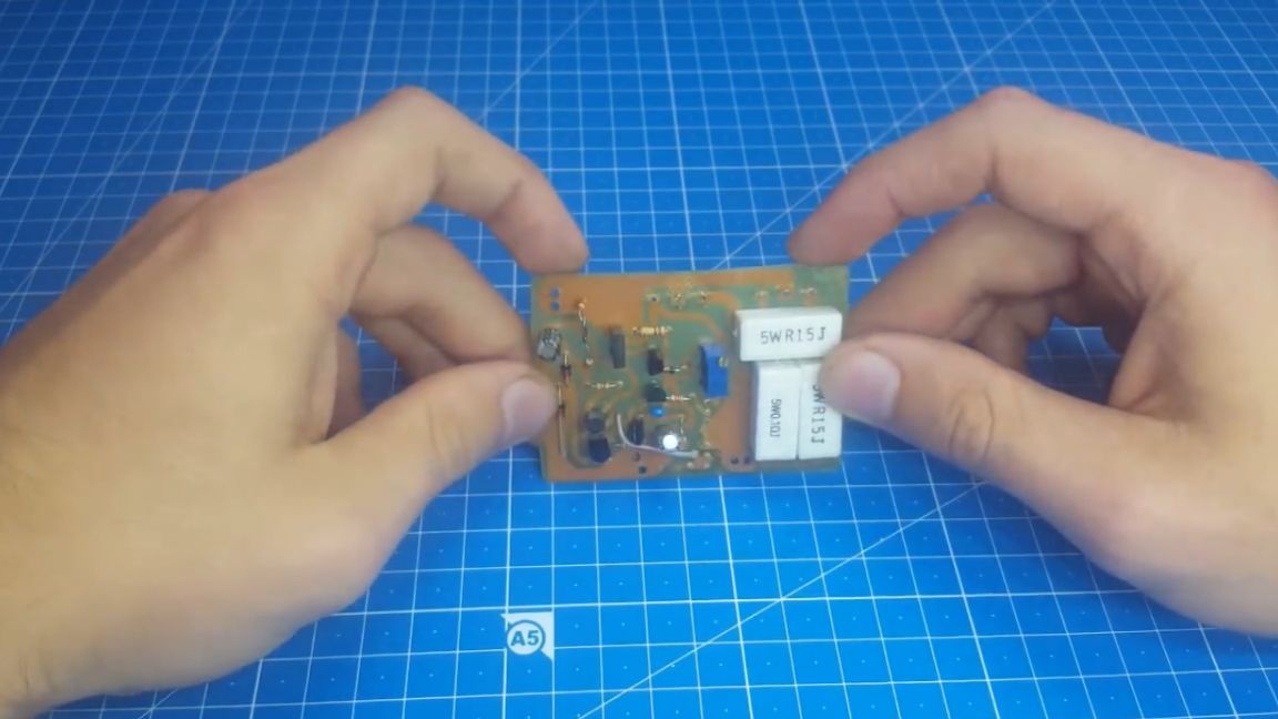
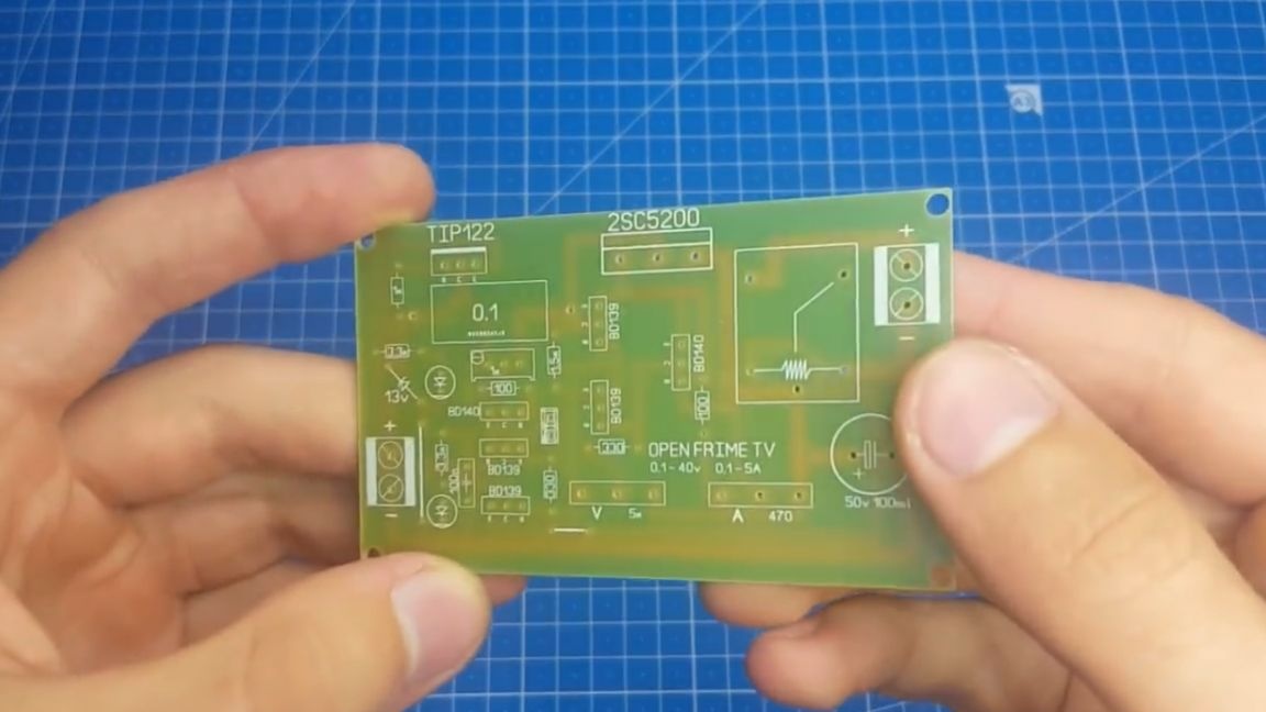
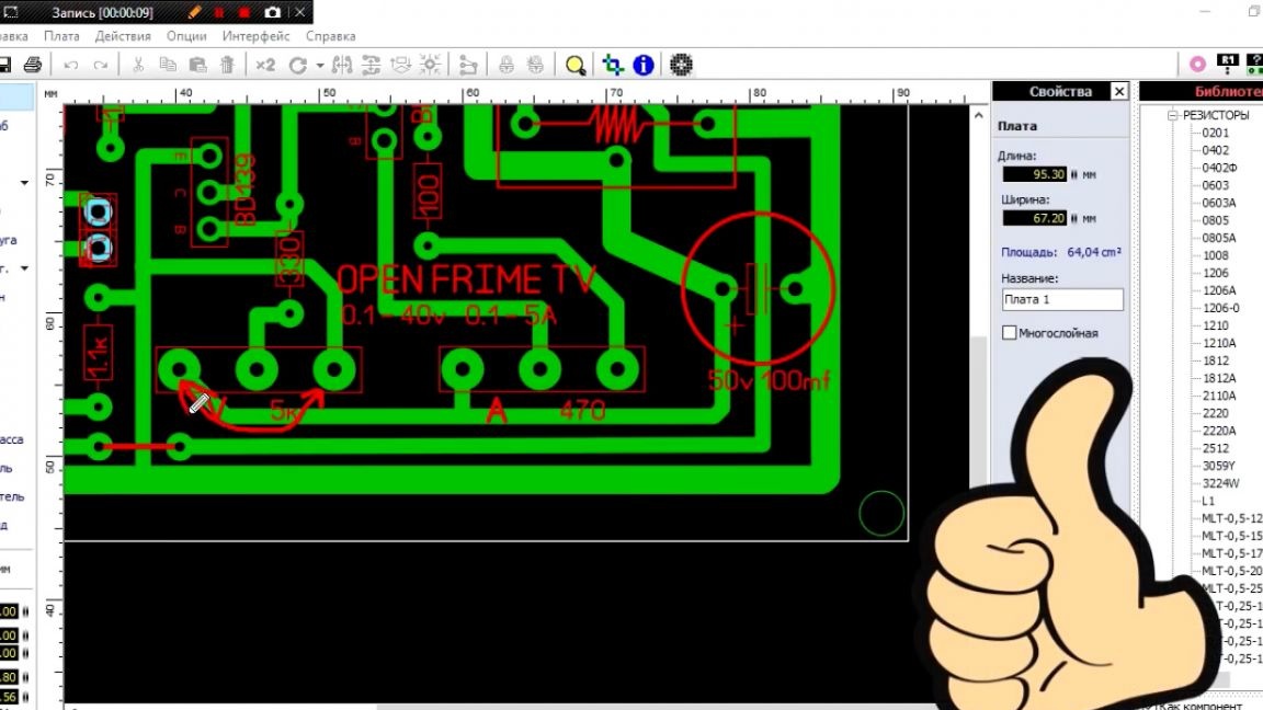
The author decided to breed a normal signet. The board turned out to be quite compact. After testing this circuit, it surprisingly proved to be excellent.
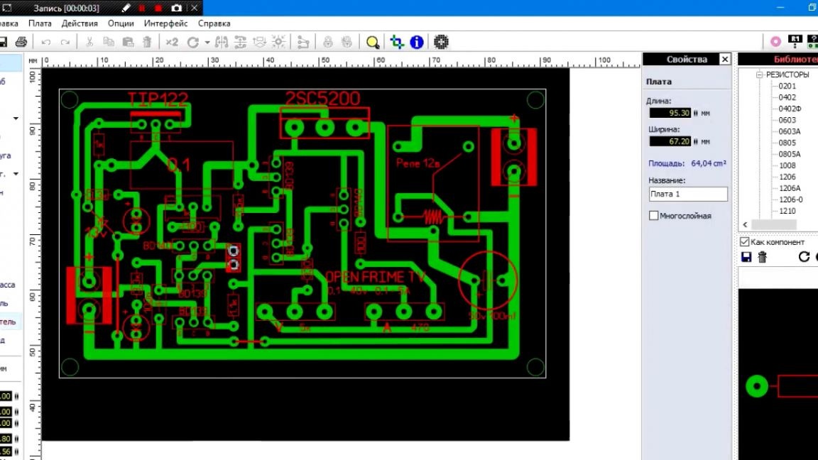
With such simplicity, the author liked it so much that he even decided to make a kit-kit from this board.To do this, you need to convert the print to a Gerber file (a file with the extension .gbr, which is a project of a printed circuit board for the subsequent production of photo masks on various equipment). Then you need to send the boards for manufacturing.
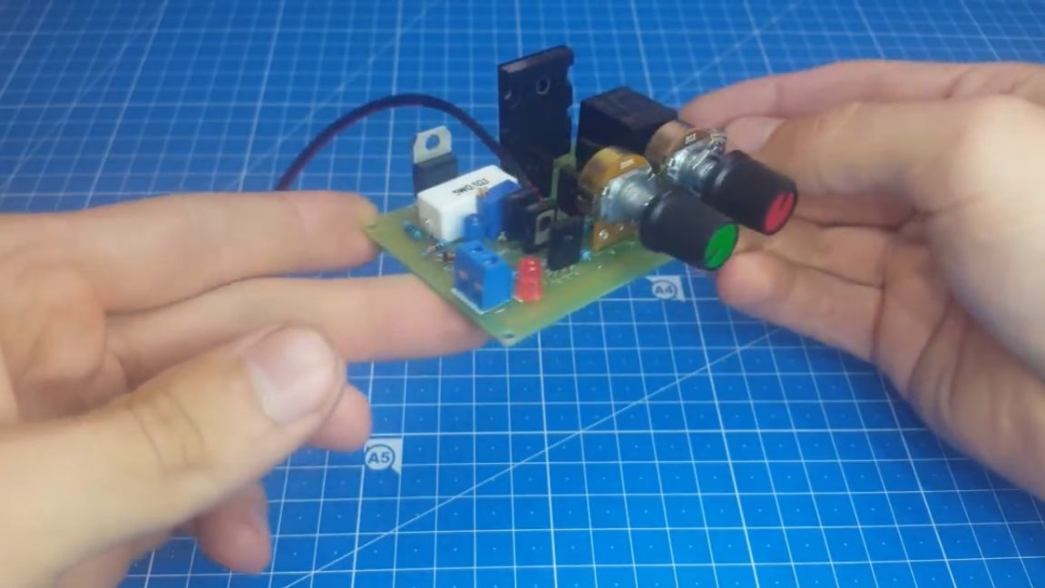
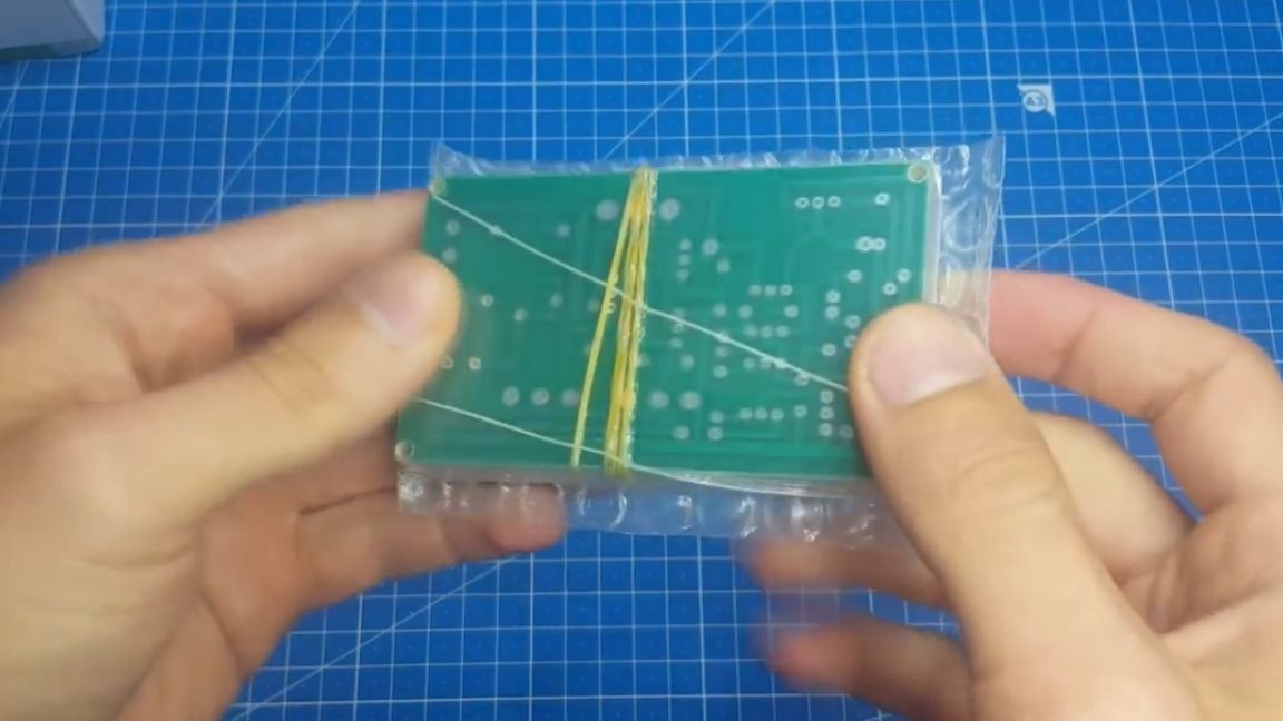
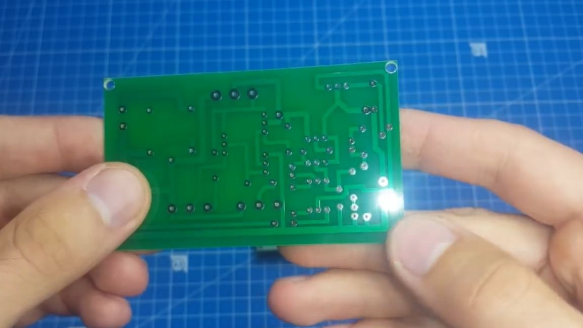
And now a couple of weeks after the order we receive our long-awaited boards. Having opened the package and examined the boards closer, we can make sure that everything turned out very high quality and beautifully.
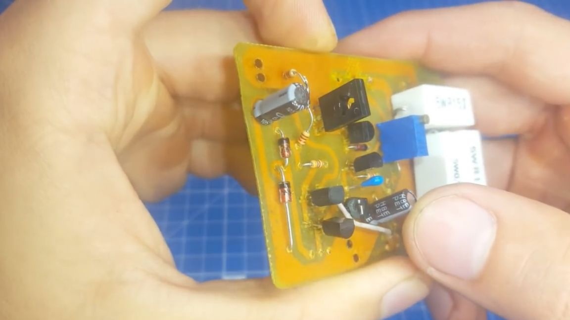
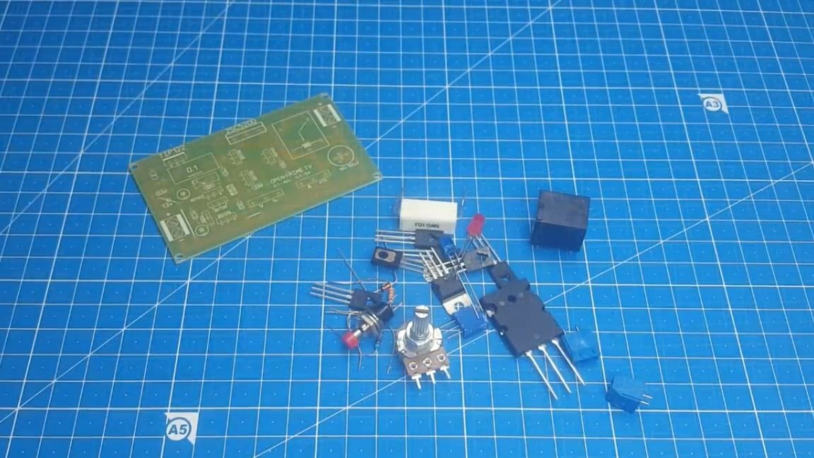
So, let's already solder this board and check it in work. There are not so many components for installation, to solder on the strength of 20 minutes, no more.
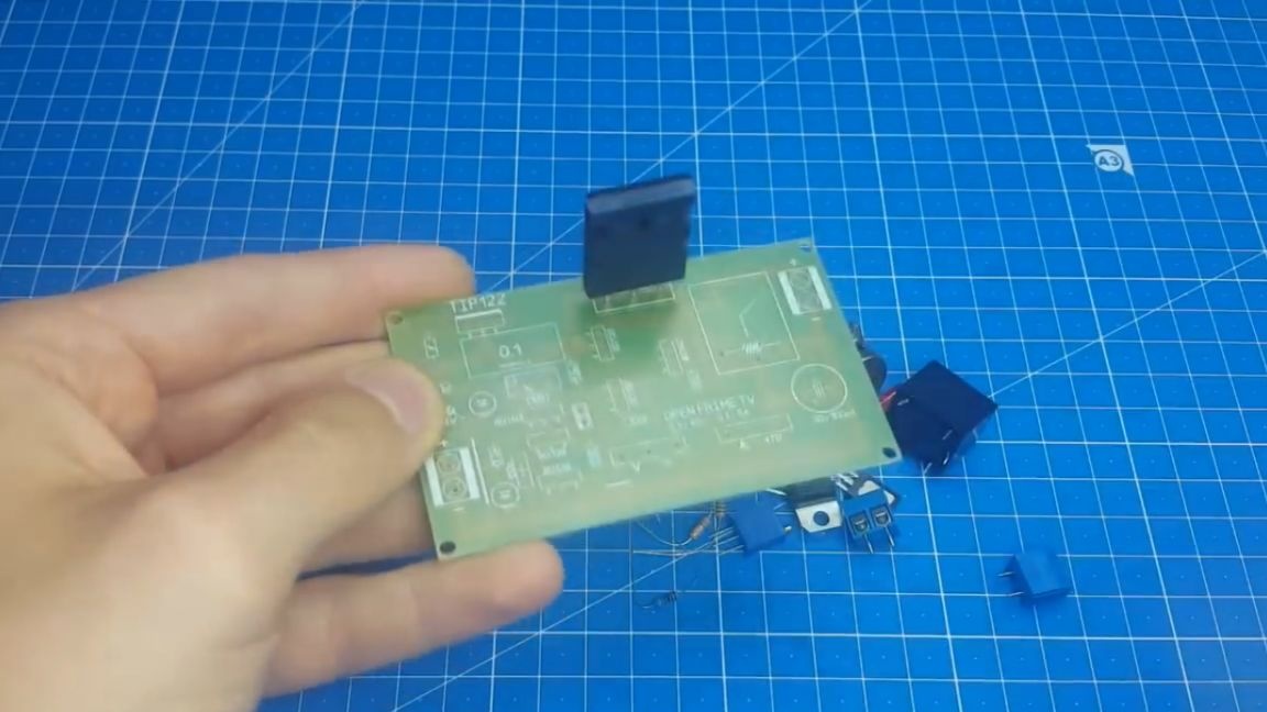
Finished with soldering. We make the first inclusion. And here we are waiting for a little disappointment. This board was not without jambs. They manifested themselves in the fact that when the knob of the potentiometer rotates to the left, the voltage and current increase, and with the right rotation, there is a decrease.
This happened because the author put the resistors for this board onto the wires (for subsequent installation on the case) and there it was possible to change the direction of rotation without any problems simply by changing the side contacts. Well, then everything else works as expected.
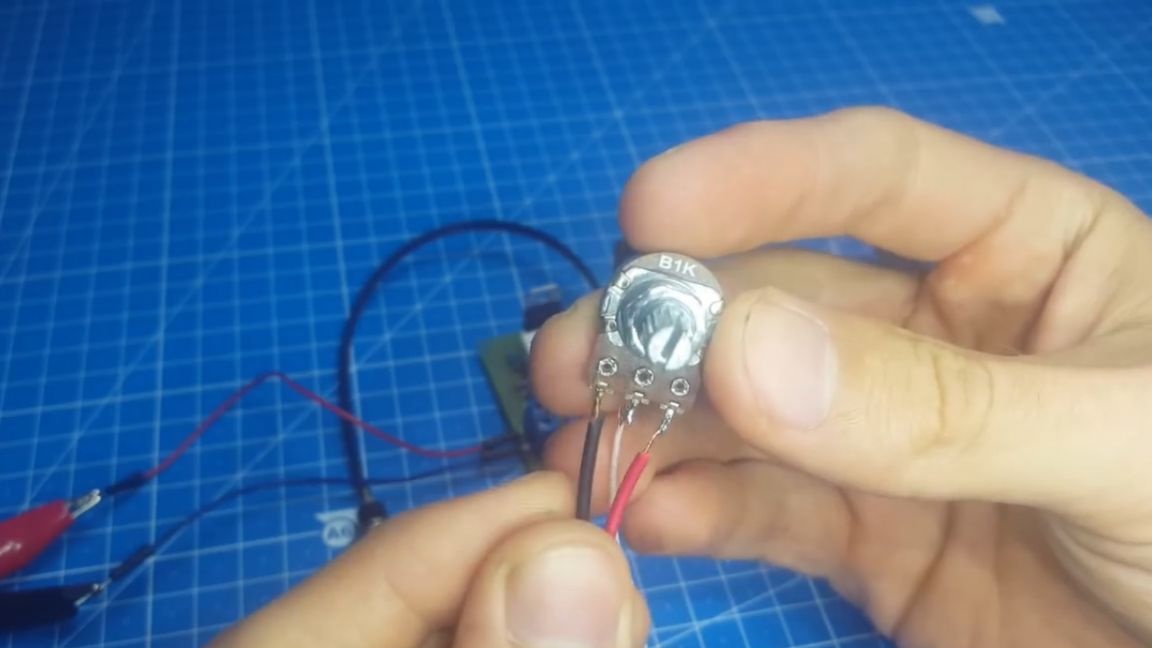
But still, the author corrected the signet, now there, with the right rotation of the potentiometer, there is an increase in voltage, everything is as it should be. So you can safely download and repeat this design (the archive with this printed circuit board is in the description under the original video of the author, you must follow the SOURCE link at the end of the article).
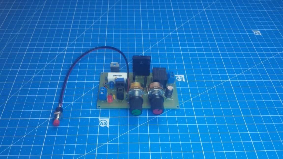
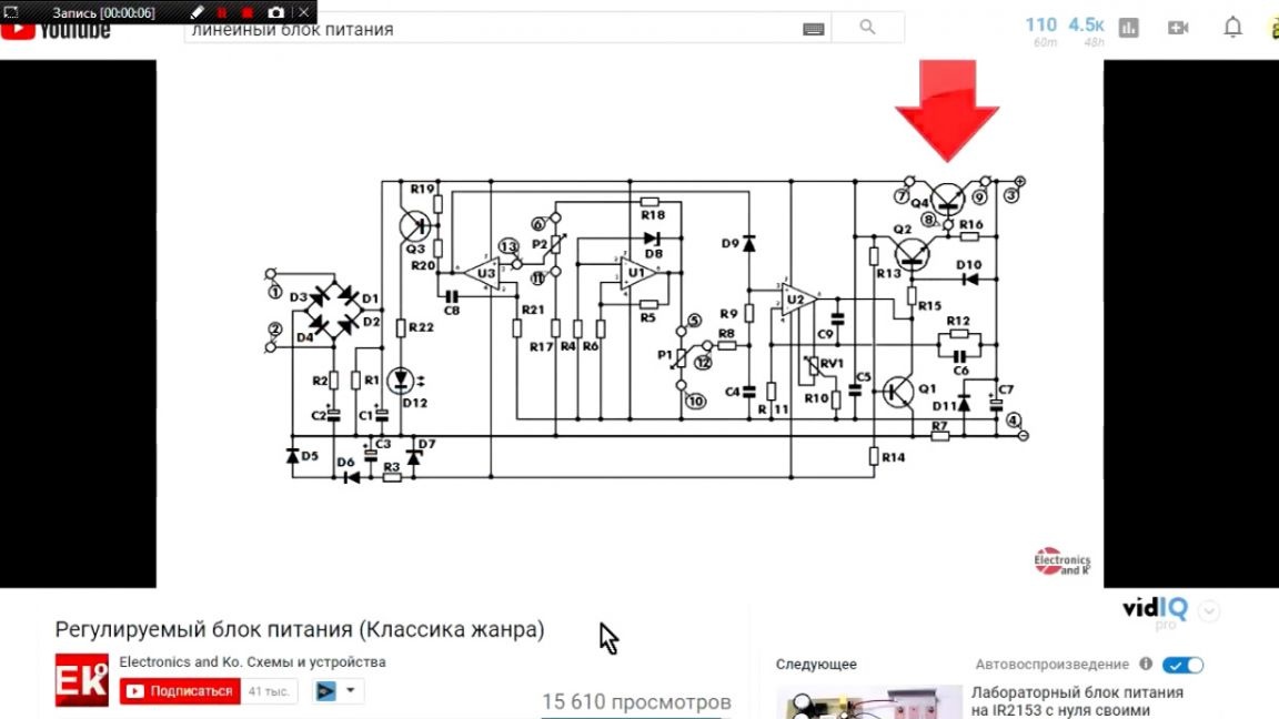
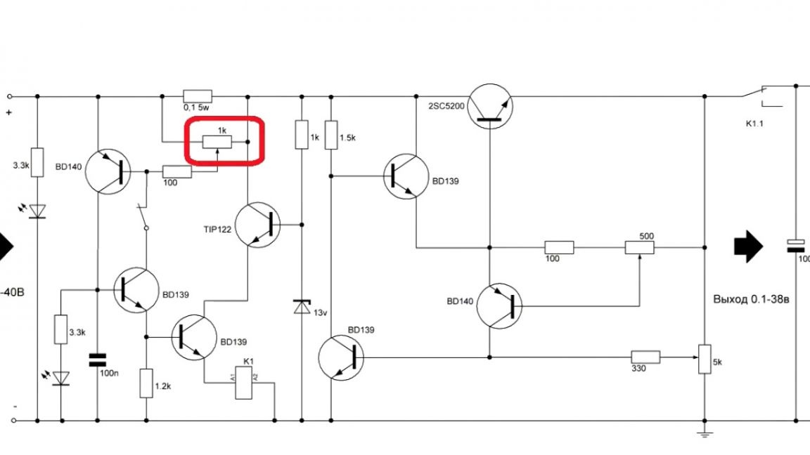
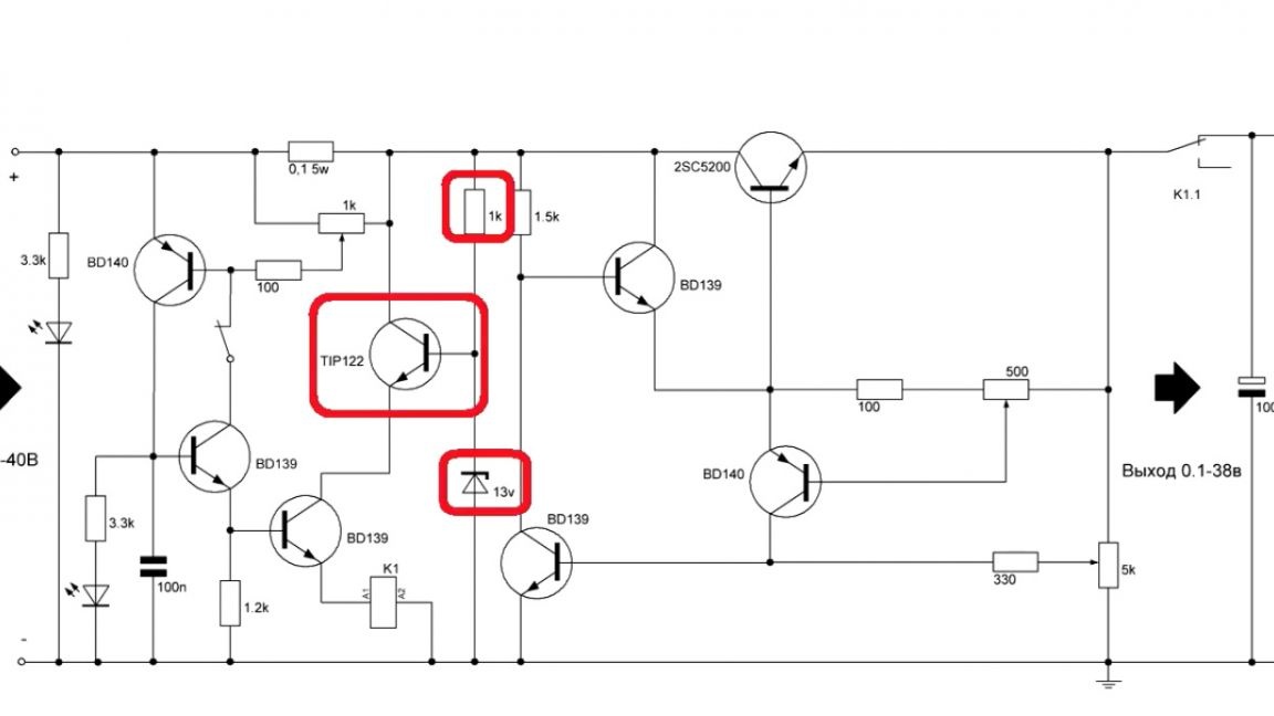
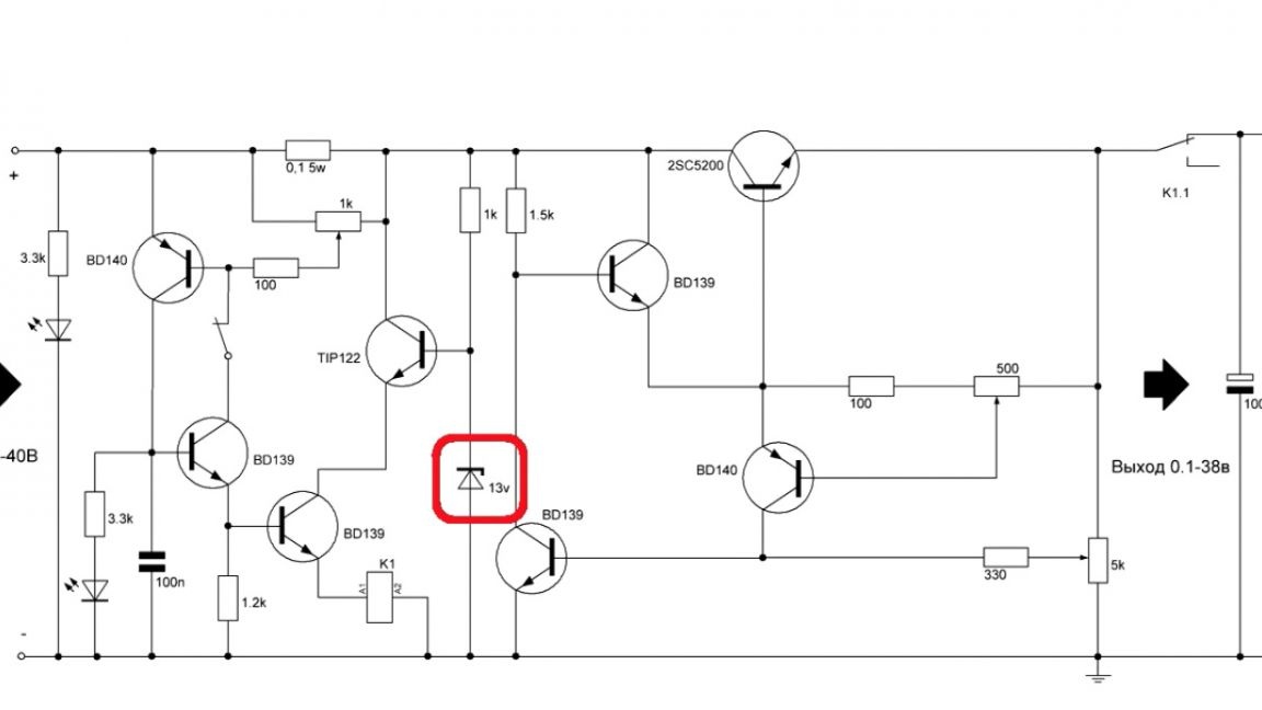
And now let's move on to a detailed examination of the circuit and the board itself. You can see the circuit on your screens.
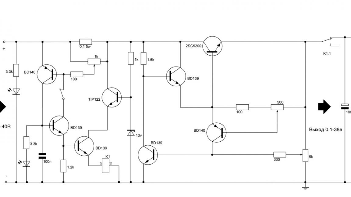
This power supply is equipped with a voltage and current regulator, as well as a short circuit protection system, which is simply necessary in such units.
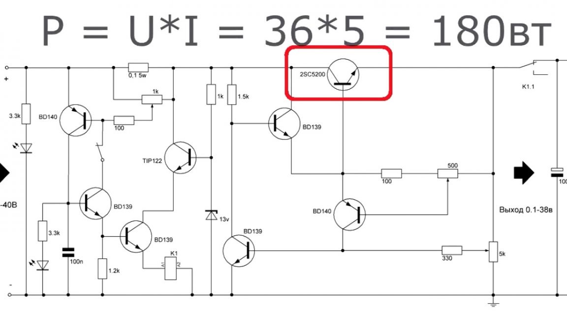
Imagine for a moment what happens during a short circuit when the input voltage is 36V. It turns out that all the voltage is dissipated by the power transistor, which of course is unlikely to withstand such mockery.
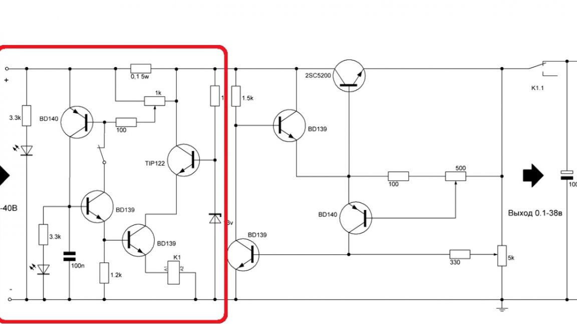
Protection can be configured here. Using this tuning resistor, we set any trip current.
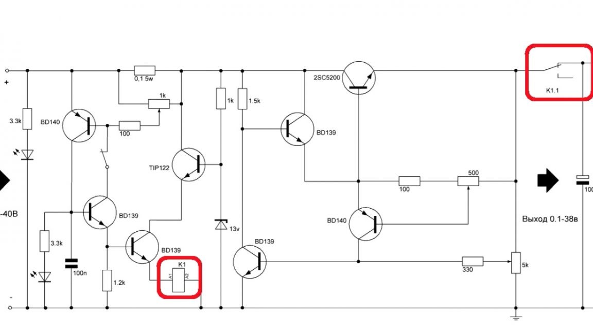
A 12V protection relay is installed here, and the input voltage can reach 40V. Therefore, it was necessary to obtain a voltage of 12V.
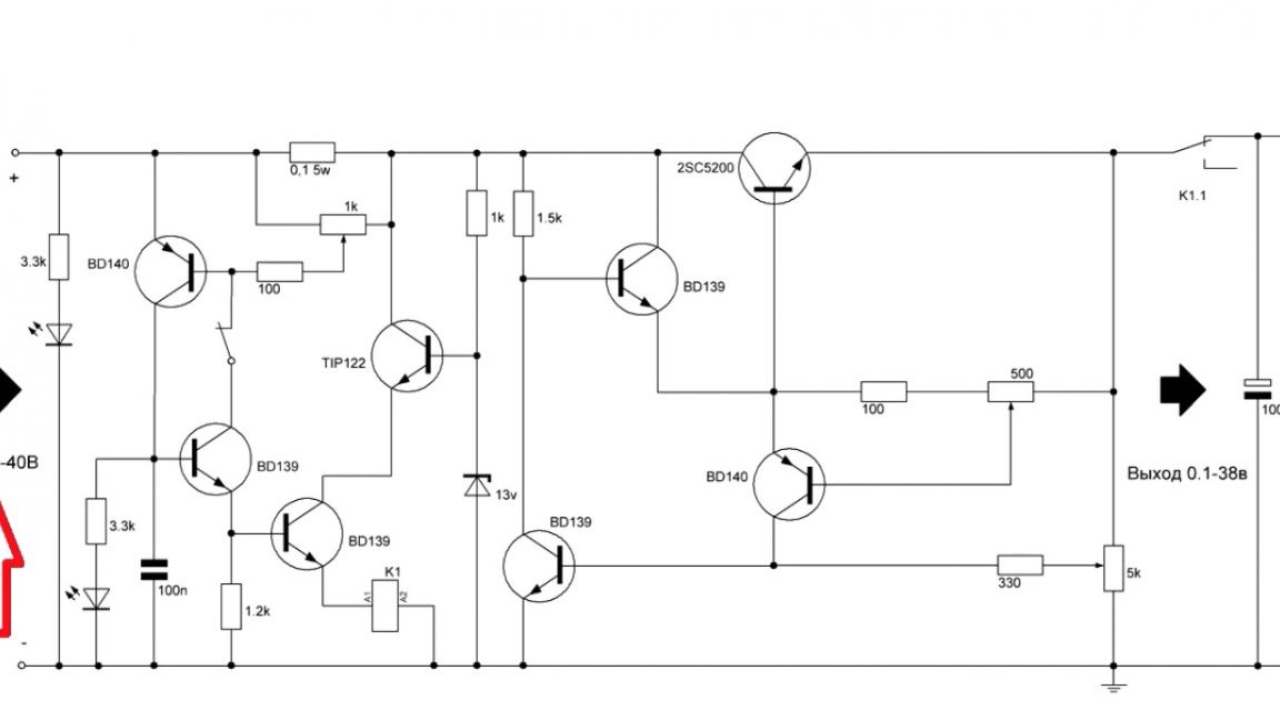
This can be done using a parametric stabilizer on a transistor and a zener diode. Zener diode at 13V, since there is a voltage drop at the collector-emitter junctions of two transistors.
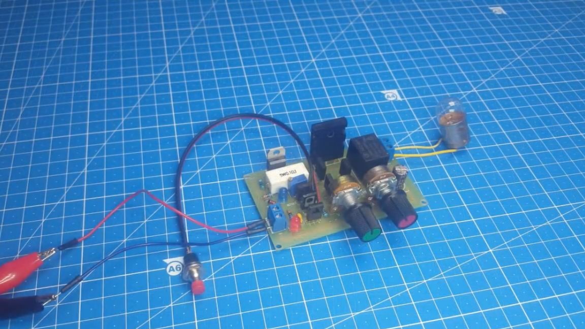
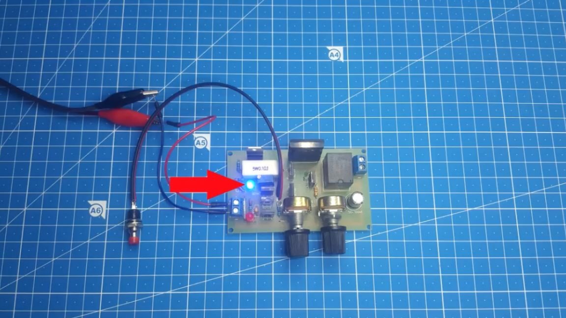
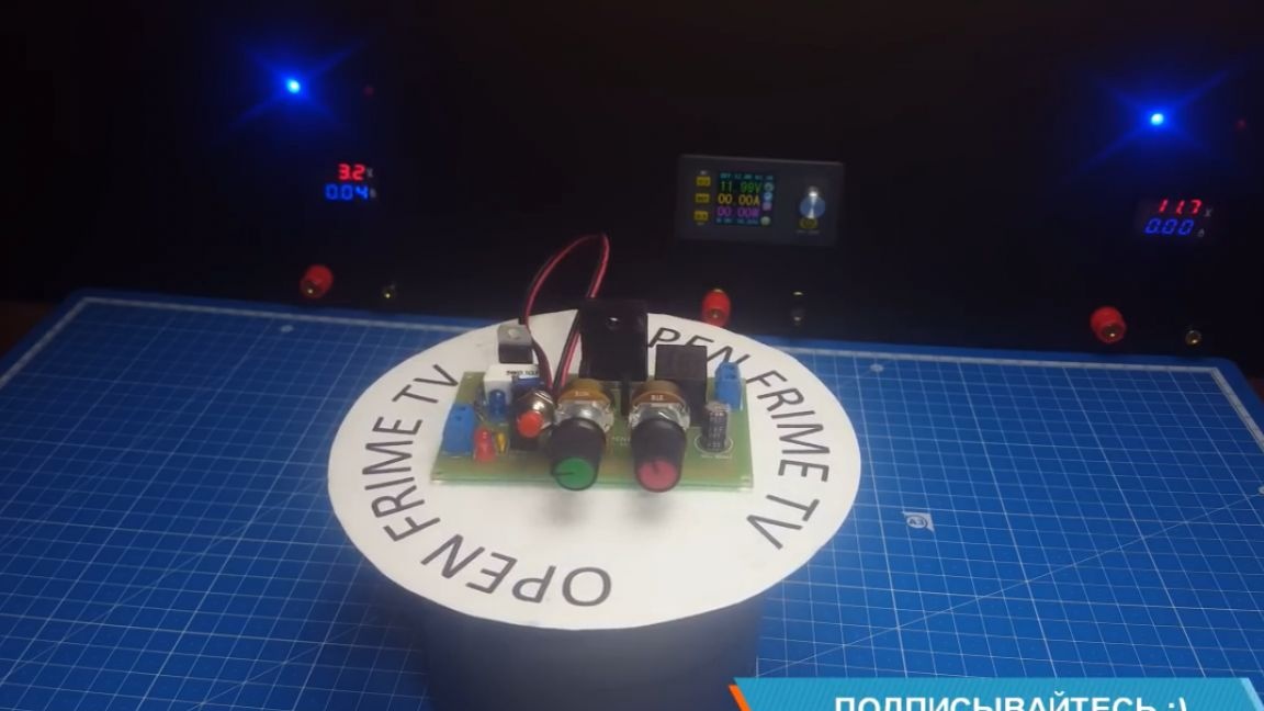
So, now you can begin to test this linear power supply. We supply a voltage of 40V from the laboratory power supply. We load a light bulb designed for a voltage of 36V, 100W power.
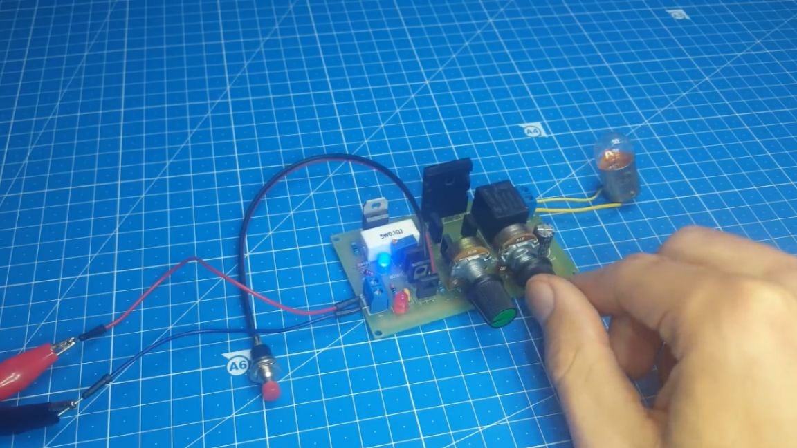
Then we begin to slowly rotate the variable resistor.
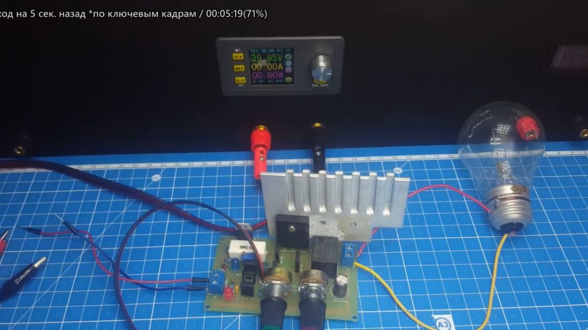
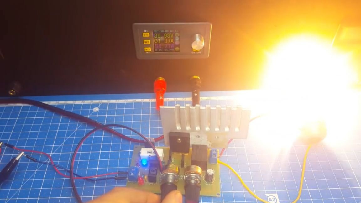
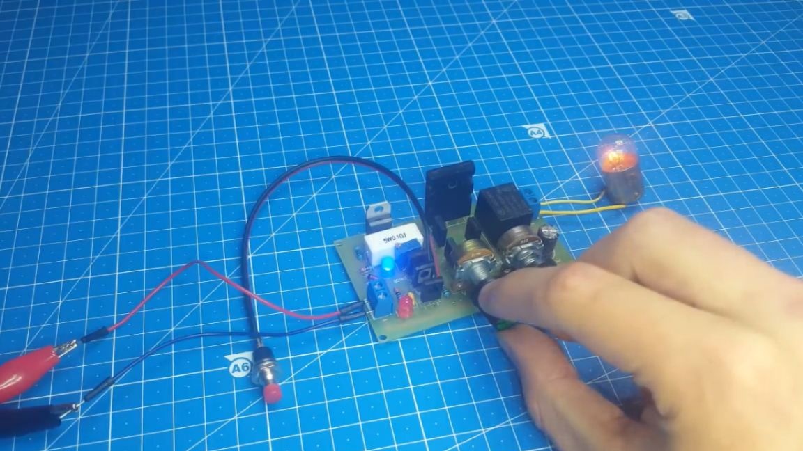
As you can see, voltage regulation works fine. Now let's try to adjust the current.
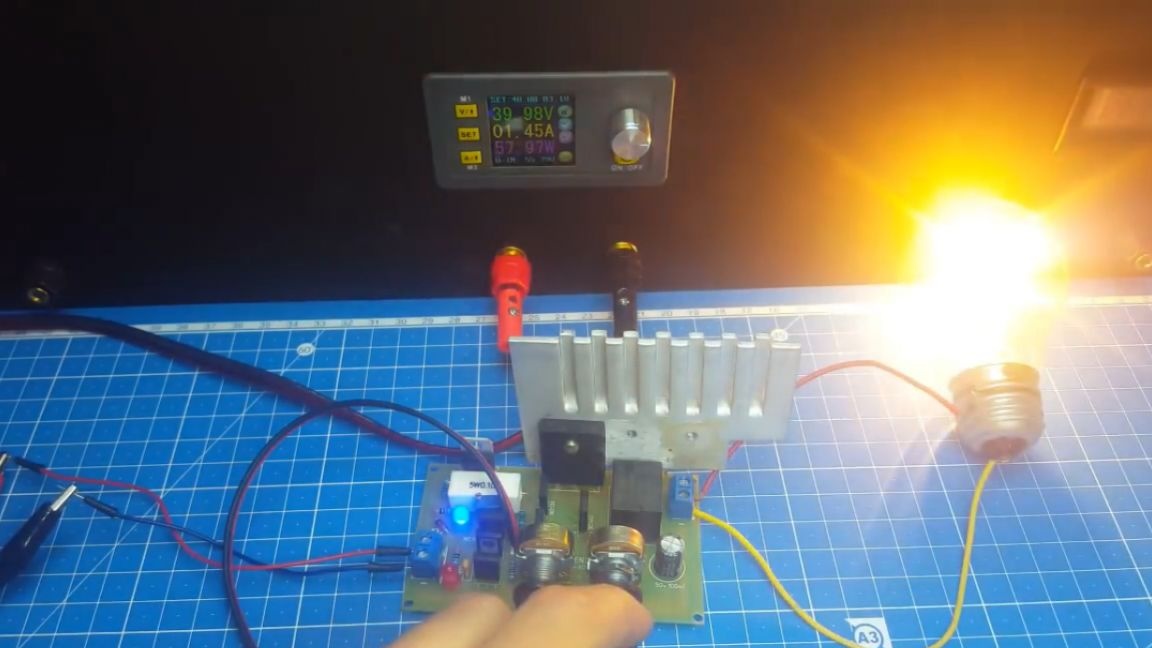
As you can see, when the second resistor rotates, the current decreases, which means that the circuit is operating normally.
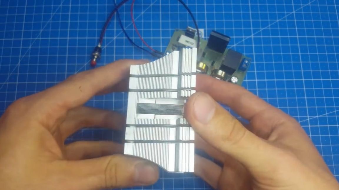
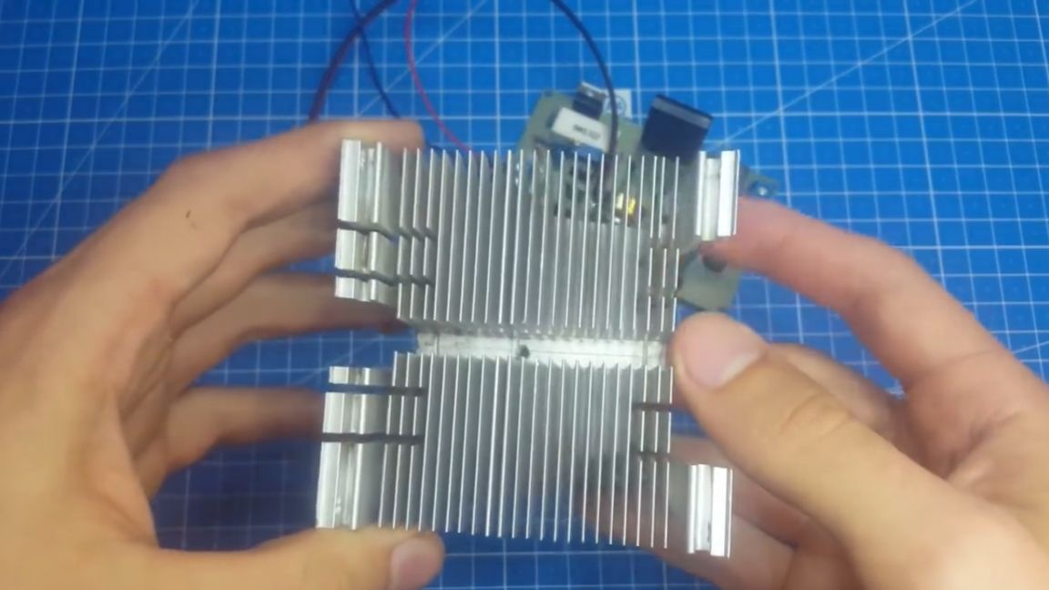
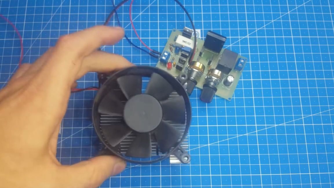
Since this is a linear block and all the "excess" voltage turns into heat, he needs a radiator of a rather large size. For these purposes, radiators from the computer processor have proven themselves perfectly. Such radiators have a large dispersion area, and if they are still equipped with a fan, then in principle you can completely forget about the transistor overheating.
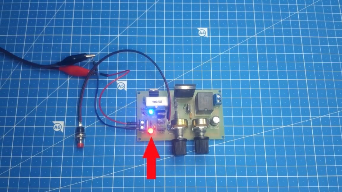
And now about how protection works. We set the necessary current with the help of a tuning resistor. In the event of a short circuit, the relay is activated. A pair of its contacts opens the output circuit and the transistor is safe.
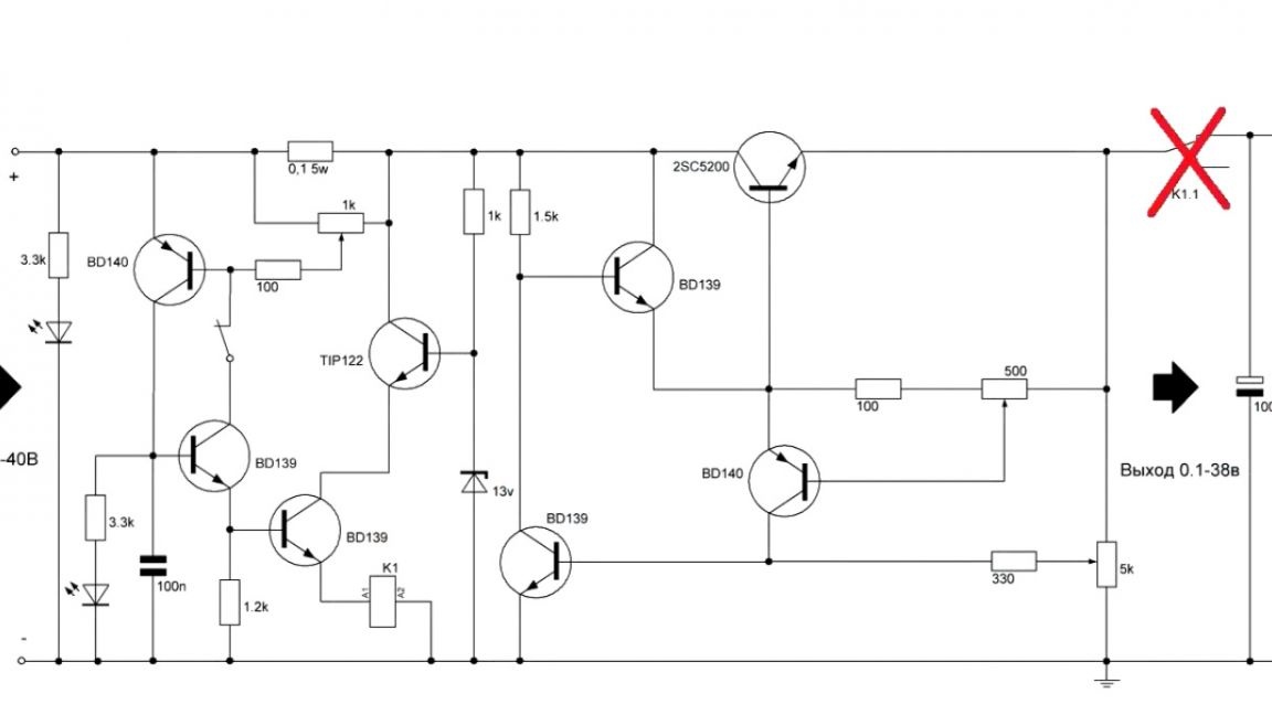
To return to normal operation, such an opening button is provided, when pressed, the protection is removed.
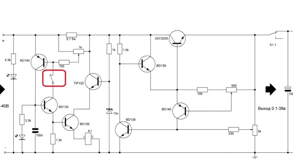
Well, or you can just disconnect the unit from the network and apply voltage again. Thus, the protection will also turn off. There are also 2 LEDs on the board.One signals the operation of the unit, and the second indicates the operation of the protection.
Summing up, we can say that the unit turned out to be very cool and is suitable for both beginners and experienced radio amateurs. So download the archive and collect such a block.
Well, that’s all. Thank you for attention. See you soon!
Video: