» Electronics » Power supplies »Reliable laboratory power supply

Reliable laboratory power supply


Not so long ago, I collected mini adjustable power supply. In principle, it suits me. Suitable for all low power homemade. Sometimes it is necessary to control the current consumption of the device, especially in the repair. Also, current adjustment is necessary when working with batteries. I decided to assemble such a laboratory power supply. Rummaging through the bins, I found the necessary components.

For LBP we will need:

- transformer;
- DC-DC converter;
- two diode bridges;
- two electrolytic capacitors;
- output terminals;
- Volt-Ammeter;
- 5V linear stabilizer;
- housing;
- a piece of sheet plastic;
- instruments.

About accessories.

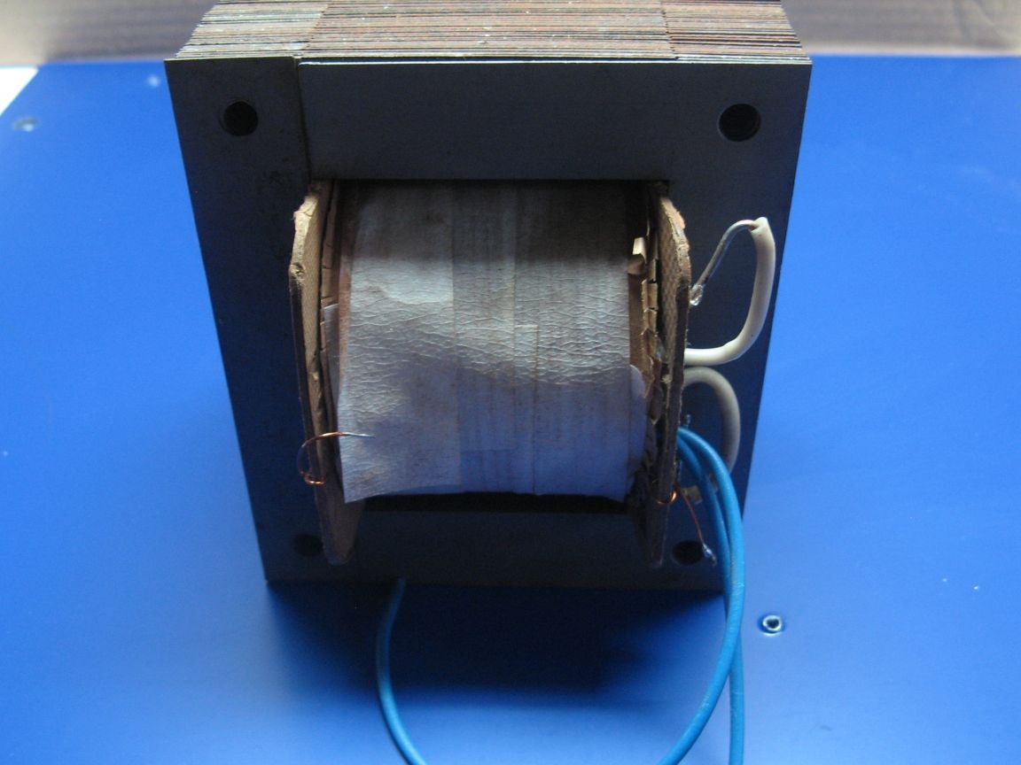
A step-down transformer of an honorable age lies a very long time ago. A transformer with a 27 V winding, has a tap in the region of 22 V. Also, a separate winding for 7-8 V was rewound, to power the Volt-Amp meter.


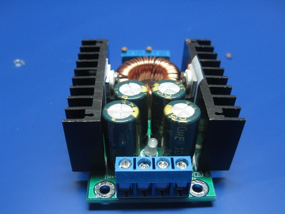
I applied a DC-DC converter from China.
The converter is powered by a voltage of up to 40 V, and at the same time it provides an output of 35 V. The current is declared 9 A, apparently limiting and with good cooling.

By the way, I do not recommend applying more than 30 V to the converter. It has a low-power stabilizer at 5 V, the maximum input voltage of which is 30 V, against the declared 40 V. It will not work for long. You can certainly refine the circuit to a higher voltage, but not about that.


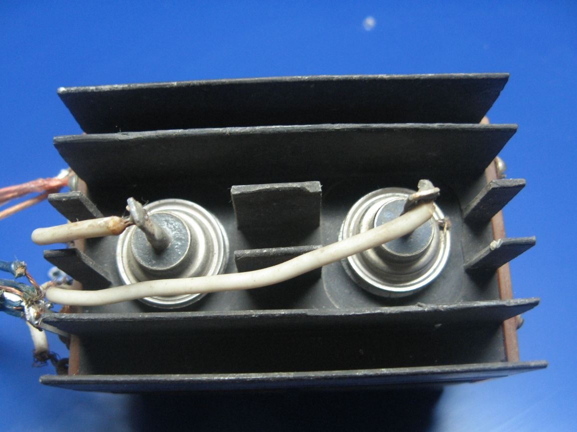
I have a diode bridge from individual diodes. Remained from the old project. D242 diodes are installed. You can apply the assembly, but as I have it, I’ll apply it.


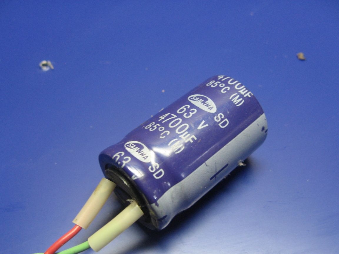
Filter capacitor at 63 V and a capacity of 4700 uF. The converter also has its own two at 470 microfarads. Selected based on 1 Ampere - 1 uF. I plan to load the power supply up to 5 A.


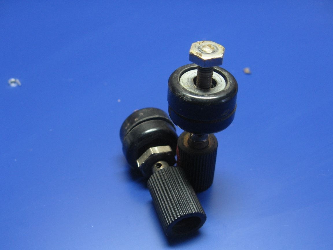
The output terminals need reliable. Found old in the bins, the current of 5 A withstand with a bang.


Volt-Ammeter from China. It has three segments, not very convenient, but it will suit me. Comes complete with wires. The maximum measured voltage is 100 V, the current is 10 A. The supply voltage is 30 V at maximum. Here, like the converter, the same power stabilizer.


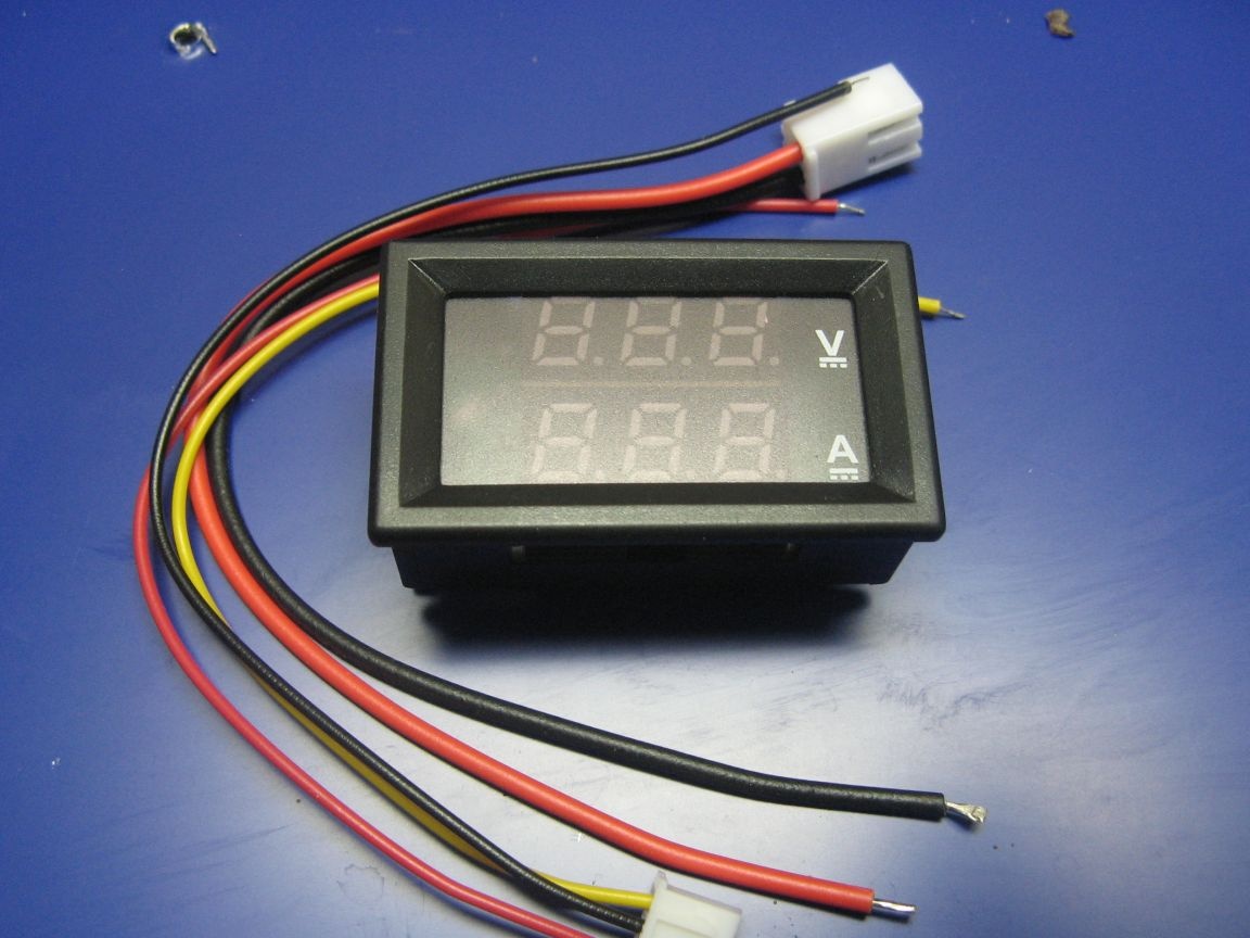
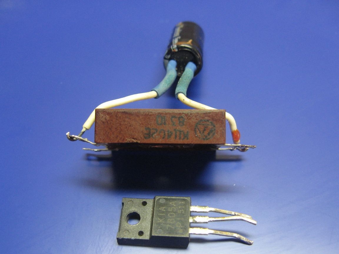
I will power the Volt-Ammeter through a diode bridge with a capacitor and a 5 V linear regulator.


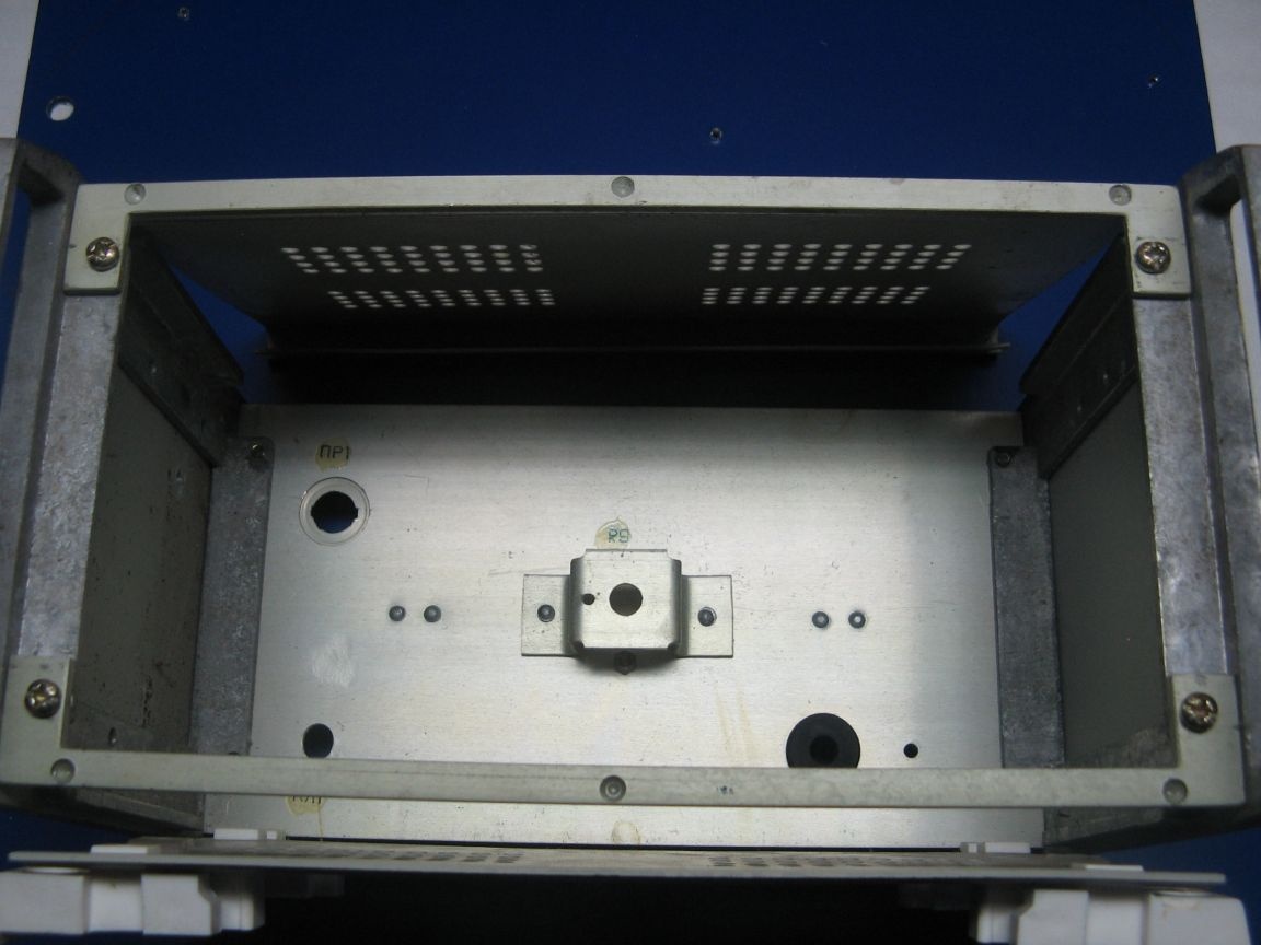
The case is from an old regulator of a soldering iron, something like a Soviet soldering station. Solid body, completely made of aluminum. I will remove the bracket on the rear panel.


The front panel will be made of composite plastic. I scored it from advertisers. It consists of PVC plastic sandwiched between sheets of aluminum.
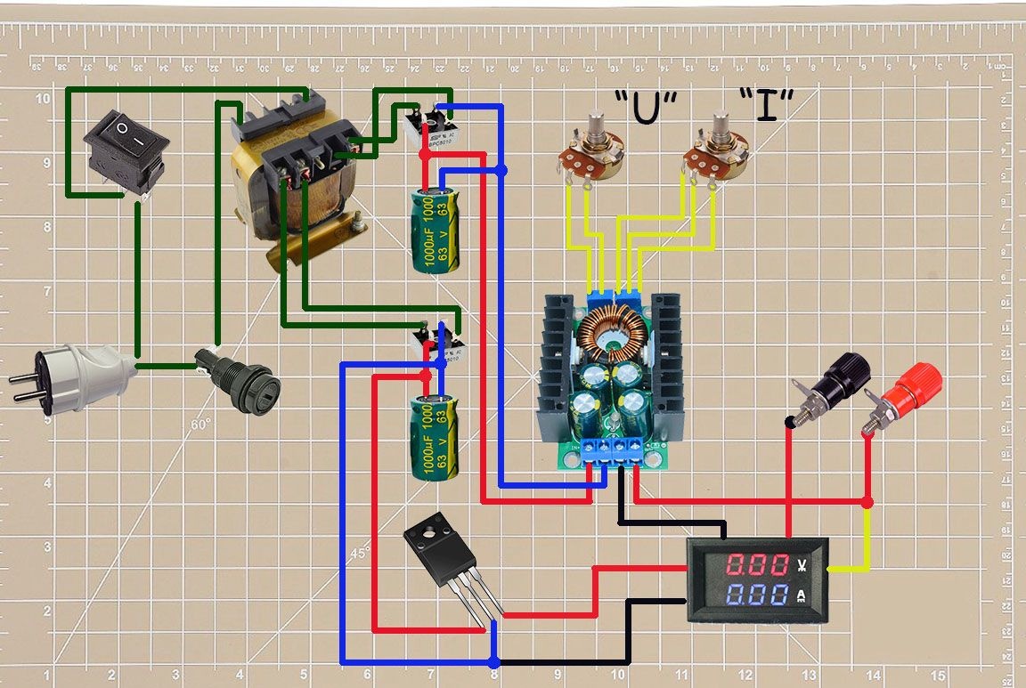


About the scheme.

The circuit has two shoulders.
The upper shoulder is power. Consists of: a diode bridge, a smoothing capacitor, a DC-DC converter. Power, negative wire goes through the ammeter.

Lower arm feeding a volt-ampere meter. It has a diode bridge with a capacitor and a linear stabilizer. If you do not set it, the readings will “float”.
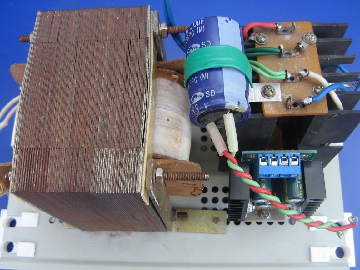


Assembly.

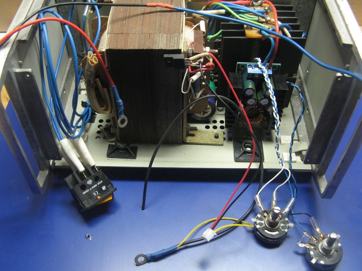
After preliminary marking and drilling holes, I install power elements. I will take the voltage and current adjustment resistors beyond the converter board. Also connected together the power winding of the transformer, the diode bridge and the converter. A capacitor was fixed between the transformer and the diode bridge. Between the right sidewall left a gap. If it gets very hot, I will install a fan.


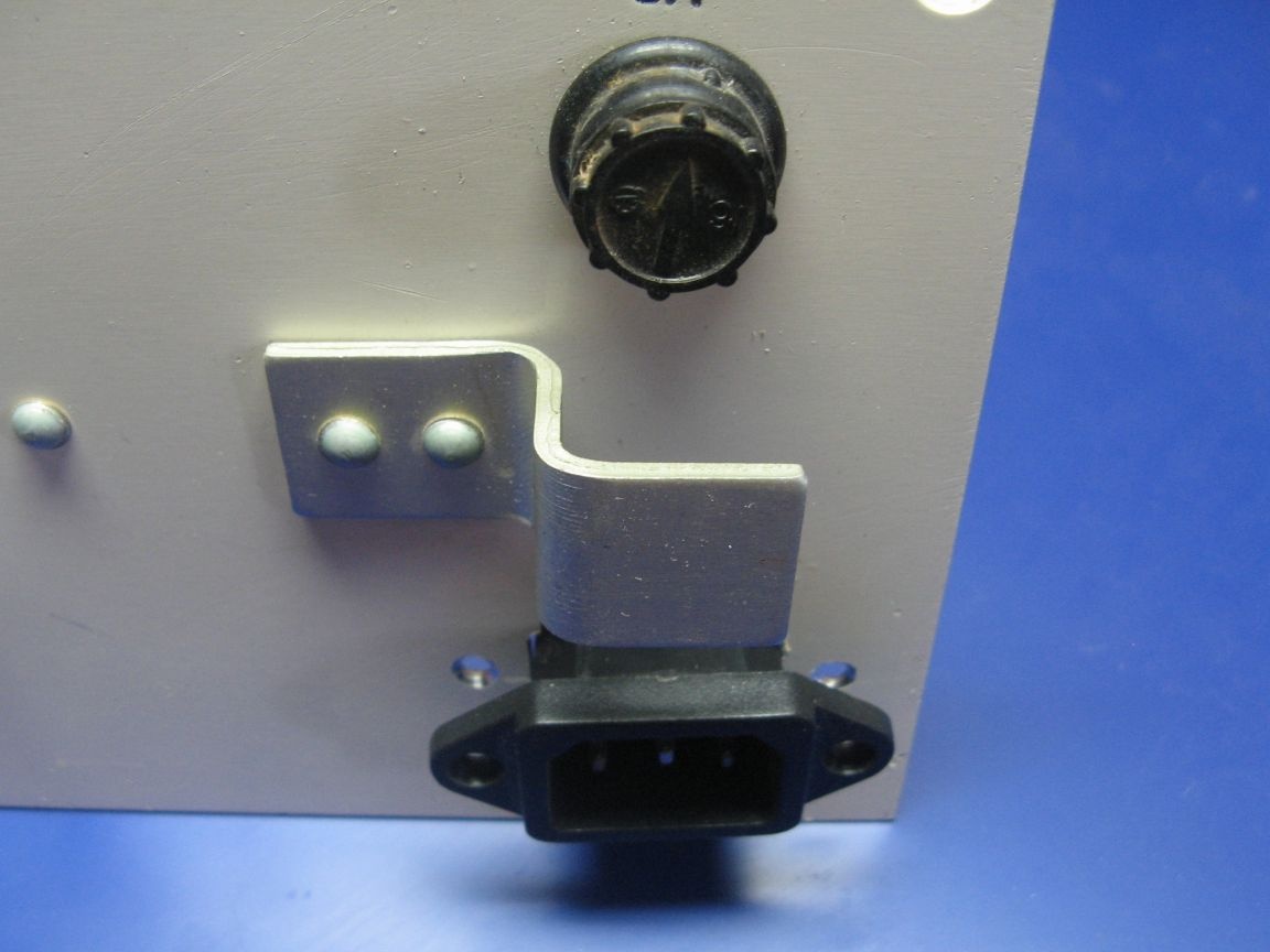
On the rear panel of the case will be installed a network connector and a fuse. Initially, I did not plan to install the connector; I wanted to make the power cord not removable. But still I decided to install, the benefit of connectors and power cords is enough.


Mark the front panel for the controls. A protective film is glued on the composite plastic, it is convenient to mark it out usually with a ballpoint pen. I cut holes and windows.


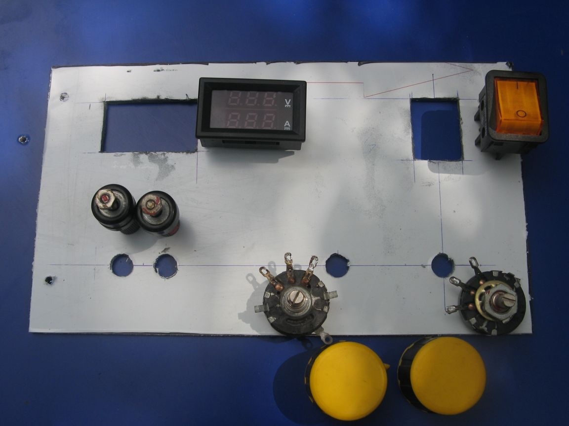
I solder the wires to the resistors. I connect the wires of the Volt-Amp meter and install its power, consisting of three parts. I fasten directly to the transformer stud. Nothing will heat up in this circuit.


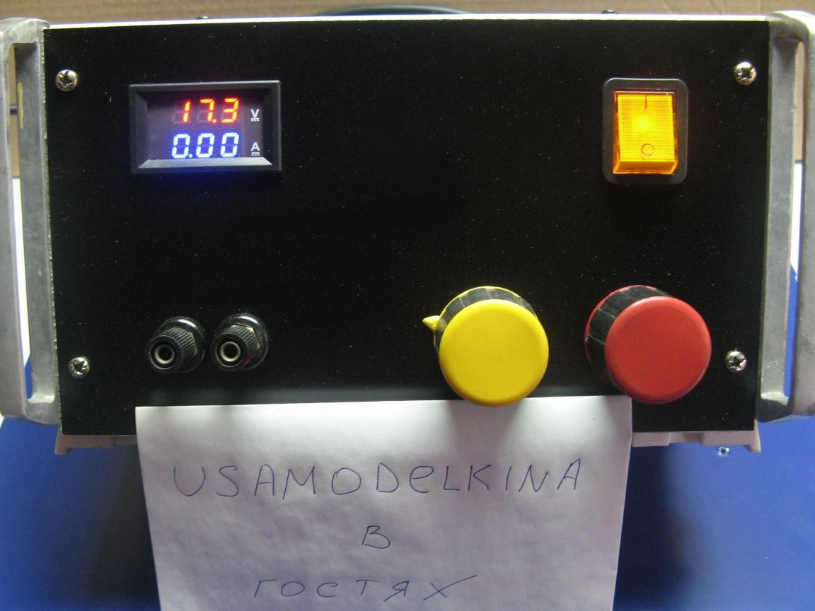
It remains to remove the protective film and install everything on the front panel. I also found another resistor handle, or rather a different color. Just the color display numbers Volt (red). The voltage is not regulated evenly, I ordered a multi-turn resistor in China. Therefore, I have not yet applied the marking of the controls. The power supply perfectly stabilizes the current. There is a paint mark on the positive terminal, not shown on the photo.


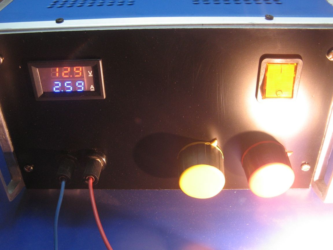
The Laboratory Power Supply is assembled and works as expected. Instead of a transformer, a pulse source can be used. I had a transformer and a housing for it, and I applied them.

Assembly video:

7.1
7.2
8.1

Add a comment

    • smilesmilesxaxaokdontknowyahoonea
      bossscratchfoolyesyes-yesaggressivesecret
      sorrydancedance2dance3pardonhelpdrinks
      stopfriendsgoodgoodgoodwhistleswoontongue
      smokeclappingcraydeclarederisivedon-t_mentiondownload
      heatirefullaugh1mdameetingmoskingnegative
      not_ipopcornpunishreadscarescaressearch
      tauntthank_youthisto_clueumnikacuteagree
      badbeeeblack_eyeblum3blushboastboredom
      censoredpleasantrysecret2threatenvictoryyusun_bespectacled
      shokrespektlolprevedwelcomekrutoyya_za
      ya_dobryihelperne_huliganne_othodifludbanclose
49 comments
Author
Regarding labeling.
ordered a multi-turn resistor in China. Therefore, I have not yet applied the marking of the controls.

There is a paint mark on the positive terminal, not shown on the photo.

He installed the radiator as he saw fit, otherwise the fan will not fit in (I plan to install).
The wires are installed on the clamps with clamps (visible on the video).
I did not want to knit a tourniquet. Yes, and the "wax" thread is over.
I subscribe to many things - simplification and contraction limit us, an amateur is not at all a synonym for mediocrity, on the contrary! An amateur is not constrained by strict requirements and limits, he can easily choose exotic solutions for his creations, but for this you should have knowledge and a rather broad outlook. The amateur himself is free to choose his level of skill and it would be good if he were on top. This is a big and difficult job, but the greater the satisfaction, the greater the feeling of not being a user but a creator.
As for the disciplines taught at educational institutions and moaning on the topic “why do you need it when you have a computer”, many of the “unnecessary” ones develop a lot of secondary, not obvious but very useful skills, looking to sweep them away is a big mistake.
As for the power supply unit - indeed, the not too competent arrangement of radiators on the factory module is striking, it would be a bit to cultivate the wires. Yes, in a good form, it would be to provide the signatures governing bodies, if they were three-colored, certainly the terminal polarity. Overall, good.
An amateur differs from a professional in that the former loves the job, and the latter earns money on it.
It is not related to quality.

1. Amateur - loves, it is connected with quality!
2.Professional - earning, it is connected with quality!
3. Not always so directly, people are different! smile
Since a certain part of the population speaks obscenely and with a hairdryer, this must be legalized!

This will be the next package! xaxa
pogranec,
And a professional in the appendage to earning can not love his job?

An amateur clearly loves and this is his conscious choice, with the choice of a profession it is not always so unambiguous, life circumstances sometimes influence it.
And a professional in the appendage to earning can not love his job?
Here this "zina" was clearly modest.
Since a certain part of the population speaks obscenely and with a hairdryer, this must be legalized!
An amateur differs from a professional in that the former loves the job, and the latter earns money on it.
It is not related to quality.
An amateur can build his thing for years.
But a professional has an order, time and money.
Those. he must do as quickly as possible and with satisfactory quality
(or to convince the customer that it is good and not expensive)
A lover is not always happy.
Will improve and redo 100 times.
And maybe for life his "masterpiece" does not finish.
[quote] That's just the process of reading drawings has not yet been computerized [/ quote] But the Chukchi is not for the reader, the Chukchi for the writer came to study! [quote] smile
FROM THE PERSON OF ADMINISTRATION EVERYONE IS INVITED TO THE SITE
I apologize, and the PERSON is aware of your authority? smile
Author
Sealed up, Still correctly 1000 microfarads per 1 A))
Here are just the processes of reading drawings have not yet been computerized. )) Yes, and it’s impossible to draw a sketch on a piece of paper without the ability to draw.
You can’t understand about the capacity. ((
It is usually customary to set the output of the rectifier to 1000 μF = 1 mF per 1 A. And you set it right, but wrote
Selected based on 1 Ampere - 1 uF.
Now, hopefully chewed for you?
Author
It's okay, it does not heat up significantly. If I put a fan, it will be normal.
About capacity ...
pogranec,
And ask your classmates
I agree, but a classmateprostrate and then it was useless to ask! smile
pogranec,
And schoolchildren coming to colleges and institutes are forced to study drawing first.
And I thought all the design processes have been computerized for a long time, I myself have not stood behind the kulman for a long time!
Well, maybe they studied at 75, but they didn’t study at 89. And can they ask your classmates to read it? I am sure, if not their profile in life, they will not read it.
And they studied in detail how to read the circuit?
I graduated from school in 1975, we studied the scheme of a single-tube radio receiver!
They also taught to read the drawing. And schoolchildren coming to colleges and institutes are forced to study drawing first. Well, where necessary. Aircraft industry for example, or construction. Yes, even sewing production, also drawings, or metalworking.
You know at school canceled plotting
As far as I remember there were taught to use pencils of different hardness, rulers, patterns, draw on paper, etc. Computers are doing it better now.
if this is the main profession, and if a hobby?
The ark was built by an amateur, the Titanic - professionals! I had to talk with lovers who, in the field of their hobby, many professionals shut up in a belt! I can explain you the way for a long time with words, and you still won’t understand, one glance at the map and everything is immediately clear!
Quote: popvovka
I always mean that, and not just me, Wikipedia too.

What did you mean?
Why is it unsuccessful?
The radiator fins are horizontally arranged.
Author
I always mean that, and not just me, Wikipedia too.
Why is it unsuccessful?
I wanted to swap the switch and voltammeter. Then he got distracted and did as is. Yes, and I would have to pull the wires from the connector to the transformer. The fuse hole was already left.
And the habit of writing with the capital. In the list, the element was written almost correctly))
If there is a fan, then without a regulator. And 5 V will be the norm.
I wanted to get confused and do it from scratch, but I did not want to flatter the scheme.
Author
It is hard to evaluate the ripple; the oscilloscope has not arrived yet. Yes, and the internet is full of detailed analysis, ripple, in principle, within normal limits.
Author
The current stabilizes perfectly, as indeed all similar converters.
Is the current stabilizing?
In general, of course, it will work, like it. But there are comments.
1.
Selected based on 1 Ampere - 1 uF.
Probably 1 mF?
2. The transducer module is not located correctly.
3.
Volt-ampere meter
Eka You respect him.))) In fact, he is a voltammeter, with a lowercase letter and in one word.
4. It is not clear why the multimeter is powered from 5 V, it is close to the lower limit (4.5 V), although it is possible to install a stabilizer at 12 V, then it is also possible to power a prospective fan from it.
5. Not thought out the location of the components. It was much more logical to arrange, when viewed from the face, the transformer on the right, and the rectifier with the module on the left: then you would not need to drag the 230 V network through the entire unit to the switch and back, and the wires from the converter to the terminals would be much shorter.
6. For a real LBP, it would be correct to have an adjustment of 0 V.
Briefly: I do not expose balls, but expressed my attitude. If you are a specialist, why do you find fault - where is the respect for others? Https: //enm.imdmyself.com/rules.html I repeat: the site for the general access of needleworkers. And the more you mess with arduino - Do not bully your nose to look at all from high. All topic is closed. FROM THE PERSON OF ADMINISTRATION, ALL ARE INVITED TO THE SITE https://enm.imdmyself.com/ TO PUBLICATION OF ITS DEVELOPMENTS, USEFUL DEVICES, DEVELOPMENTS. All pleasant DIY!
About the resistors, it is dimly written, obviously not for those who will try to copy from the picture. )))
And according to claim 1 - the pulsations were not evaluated?
And they studied in detail how to read the circuit?
Author
Here is a constructive question.
Voltage from 1.4 volts to 28 volts. The current loaded 5 amperes at 12 volts. Short-circuit current, but for a short time, about 9 amperes.
I will take the voltage and current adjustment resistors beyond the converter board.
Quote: pogranec
we didn’t make out schemes at school

Did you skip physics lessons? Section "Electricity" xaxa
By the way, who ever came up with a schematic? and how did scientists describe schemes before?
Approximately as in the figures below?


Particularly pleased with the scheme from the physicist Aldini-)))
Yeah, and then questions, but what does that mean?
The scheme is not intended for repetition by specialists.

Yeah, not specialists immediately burn trance. One hundred percent will apply 220 to the winding in which the "wire is thicker" =)))))
And this is not the limit! There are unique fools that describe schemes with words, such as: "solder the right foot of the stabilizer smile to the resistor and plus the smile of the LED ...".

Thanks for the compliment, Ivan respekt
so I had drawing and astronomy, but we did not make out the schemes at school.No, in principle, if I really need it, I’ll figure it out, especially since the education is somewhere nearby, but the picture is clearer and faster in time. And given the fact that the site is not professional, a person might want to do it, but, entangled in the schemes, spit and quit.
As for higher mathematics, the time is different. He has basic knowledge, but otherwise, you all manually counted, but he scored in a computer and the calculations are ready. It is neither worse nor better; it is simply different. This is how to make a door on a machine or manually. Why does a CNC operator know wood species? He was given a template, it works. But in fact that there is a door, that is here.
2 questions to the author:
1. What are the characteristics of the PSU?
2. Trimmers, judging by the description, did not drink out? Included in the parallels?
Quote: Nruter
Now they do not draw diagrams, but the pictures are connected with colored lines ...

And this is not the limit! There are unique fool , which diagrams describe in words, such as: "right foot smile solder the stabilizer to the resistor and plus smile LED ... "
Quote: pogranec
Dislike set.

I'm on the drum that put me. And your position for me is extremely disappointing ...
Have you heard that in high school they returned the subject "Astronomy"? In my time, he was always there. Therefore, my generation can find the Big Dipper in the sky. And I had drawing at school, and at institute. I recently asked one student how higher mathematics is being taught. Answers - one subject two semesters. And I had "Higher mathematics", "Functions of many variables", "Linear algebra with applications to analytic geometry", "Probability theory and mathematical statistics". And all this is 4 semesters.
Therefore, now they do not draw diagrams, but connect the pictures with colored lines ...
It’s ridiculous. On the drum, playfully or not, and put dislike.
You know, school drafting was canceled. If, for example, when we make a table, we will lay out drawings, a generation after the USSR they will not be understood at all. What to do? Learns to read drawings, diagrams, etc. I agree if this is the main profession, and if a hobby? Throw and not do an electric bike because all the circuit diagrams, not drawings?
Quote: Mikhail Mazur
Nruter_у - dozlik

I have these toys on the drum. I do not collect likes here.
If a person considers himself a specialist and undertakes to make an electronic device, then at least he should be able to read the circuits and know the designations on them.
Accessibility is great. How, in this case, people understand the "footcloths" of the program code published here arduino? Enough extra space or whatever sign and tryndets will not work.
So, took up electricity or electronics, be kind - spell it out correctly. With water communications similarly
popvovka,
Why is this a continuation

Unfortunately, you are not alone. Recently, our Ministry of Education and Science came to parliament with a bill to simplify the grammar of the Russian language, such as writing and speaking, coffee, etc. etc. She argued that if people say that, then it must be legalized! It is thought that evolution can have prospects, degradation is unlikely - however, this is only my personal opinion ...
Author
Why this continuation, I did not understand.
There are resources for a wide range of people, this is the site.

If you will, I will continue to develop your thought! The vast majority of representatives of the "wide circle of people" that I know when discussing any technical (and not only) problems are not shy about using profanity that is understandable to everyone! What
Public Consumption Site
xaxa
Author
I mean the same. There are resources for a wide range of people, this is the site.
popvovka - like, Nruter_y - dozlik - I explain the reason: many do not belong to morons, and specialists can easily reproduce the scheme from the "layout" drawing, and on their own. A site for publicly available "consumption", although specialists also drop in here.
Author
Yeah, and then questions, but what does that mean?
The scheme is not intended for repetition by specialists.
Here, draw me a diagram of water communications, I don’t understand anything. If there is a layout, I’ll understand everything at once.
Try to draw a normal circuit diagram of the device, and not a layout for morons

We advise you to read:

Hand it for the smartphone ...