» Electronics » Sound and Acoustics »DIY do-it-yourself plywood speaker

DIY portable plywood speaker


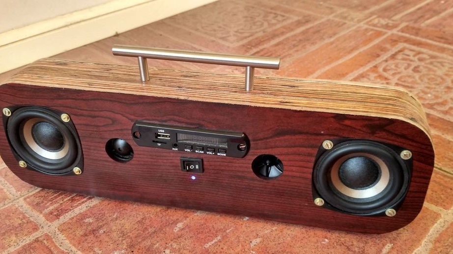
Good day to all. Today I will please music lovers and ordinary people who love a good, loud sound.
This time I will show you how to make speakers from inexpensive materials. This idea is not mine, the author of this idea is a student from SRM University "patrick panikulam" can visit his page on instructables website. I just translated his article into Russian, for those who do not understand English. I will try to convey to you the whole process of work and I hope that you will not have any problems. Well, let's begin, we will need.


DIY portable plywood speaker


Materials:
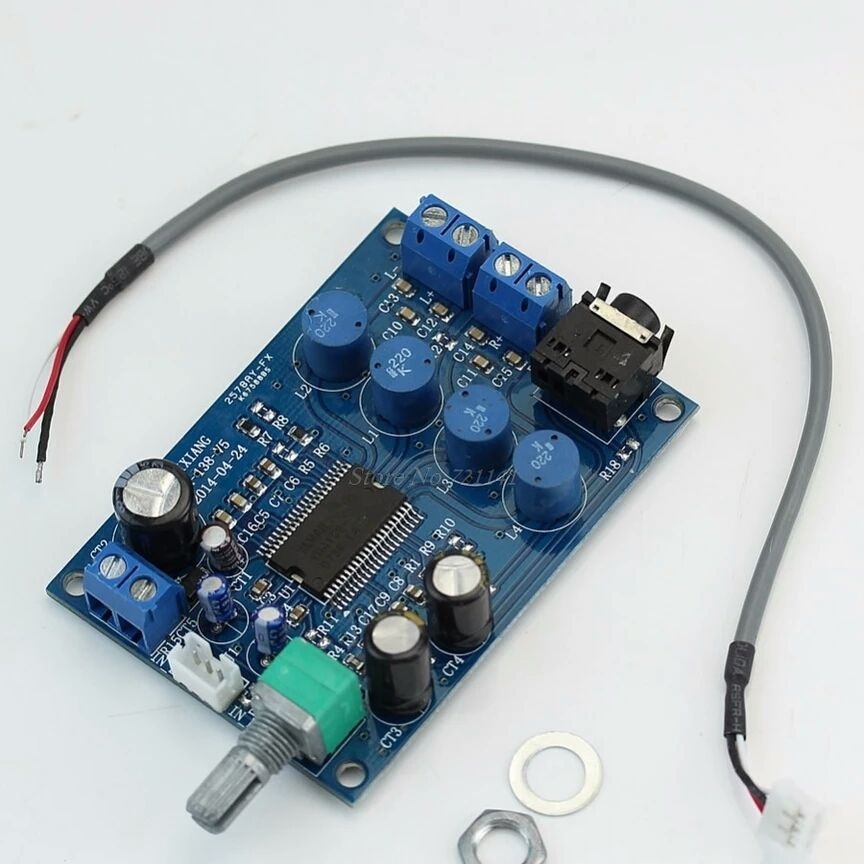
1. YAMAHA TA2024 Amplifier x1 ()
2. 3-inch, 15 Watt speakers x2 ()
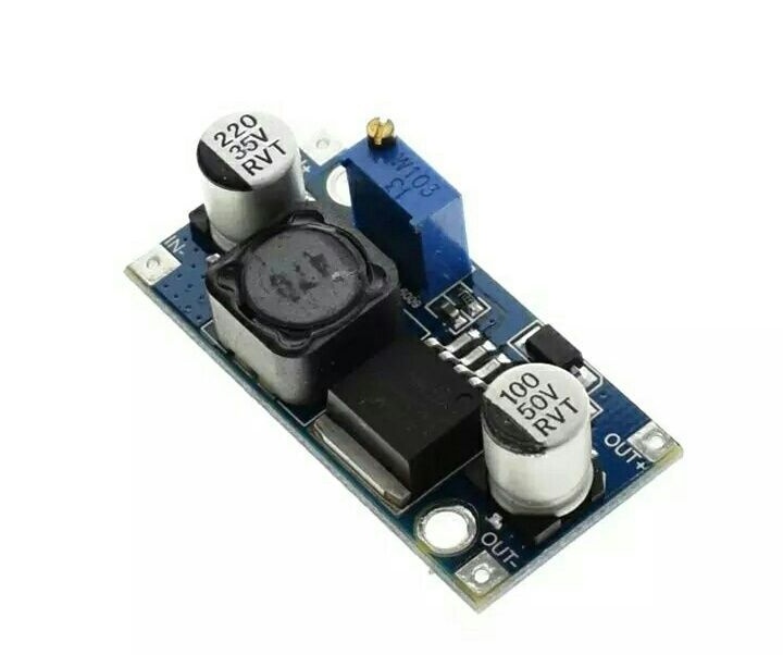
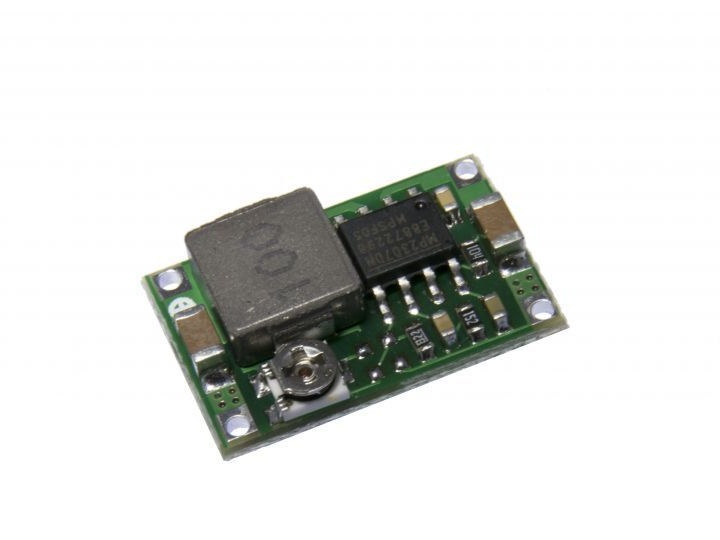
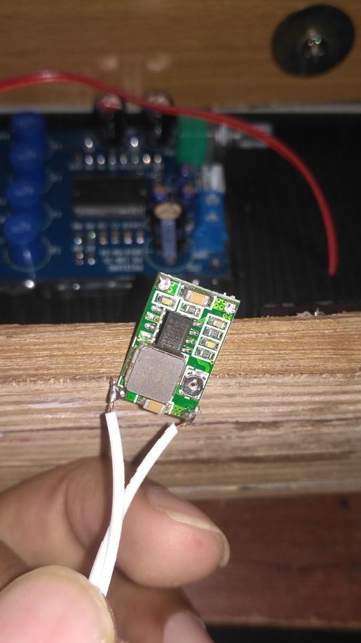
3. DC-DC buck converter ()
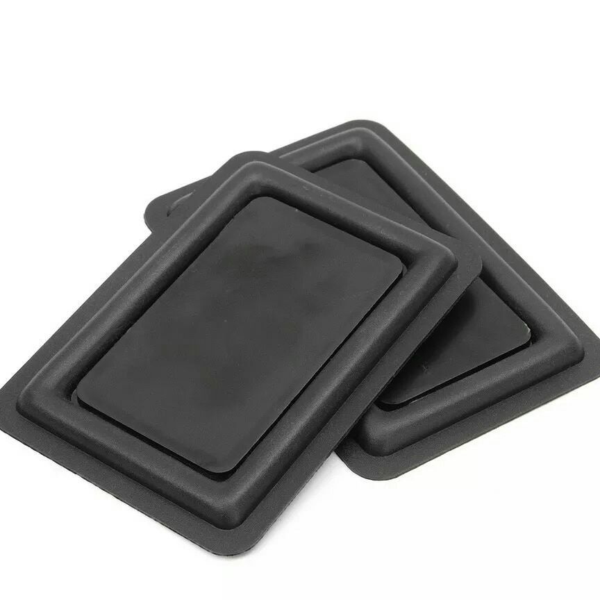
4. Passive radiators (60X90 mm) x2 ()
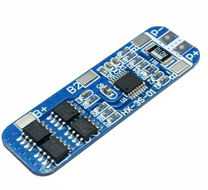
5. Charging board 12V 18650 10A BMS x1 ()
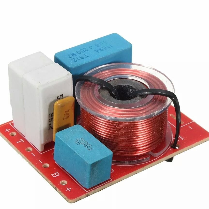
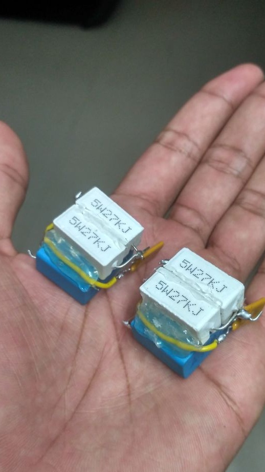
6. Frequency crossover x2 ()
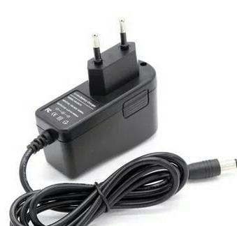
7. Charger 12.6 V (2.1 mm plug) x1 ()
8. DC-DC boost converter x1 ()
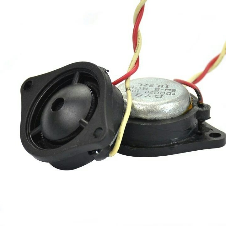
9. Tweeters x2 ()
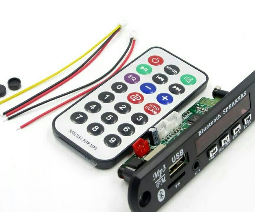
10. Bluetooth 12V MP3 WMA Decoder x1 ()
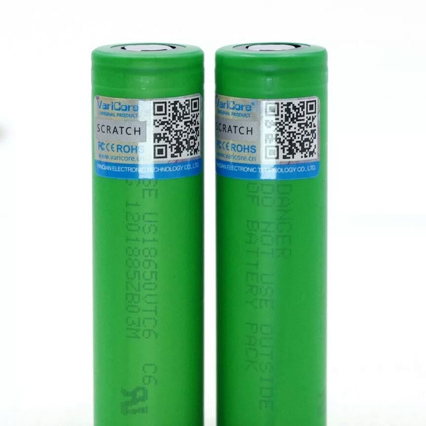
11. Battery 18650 (capacity of your choice) x3 ()
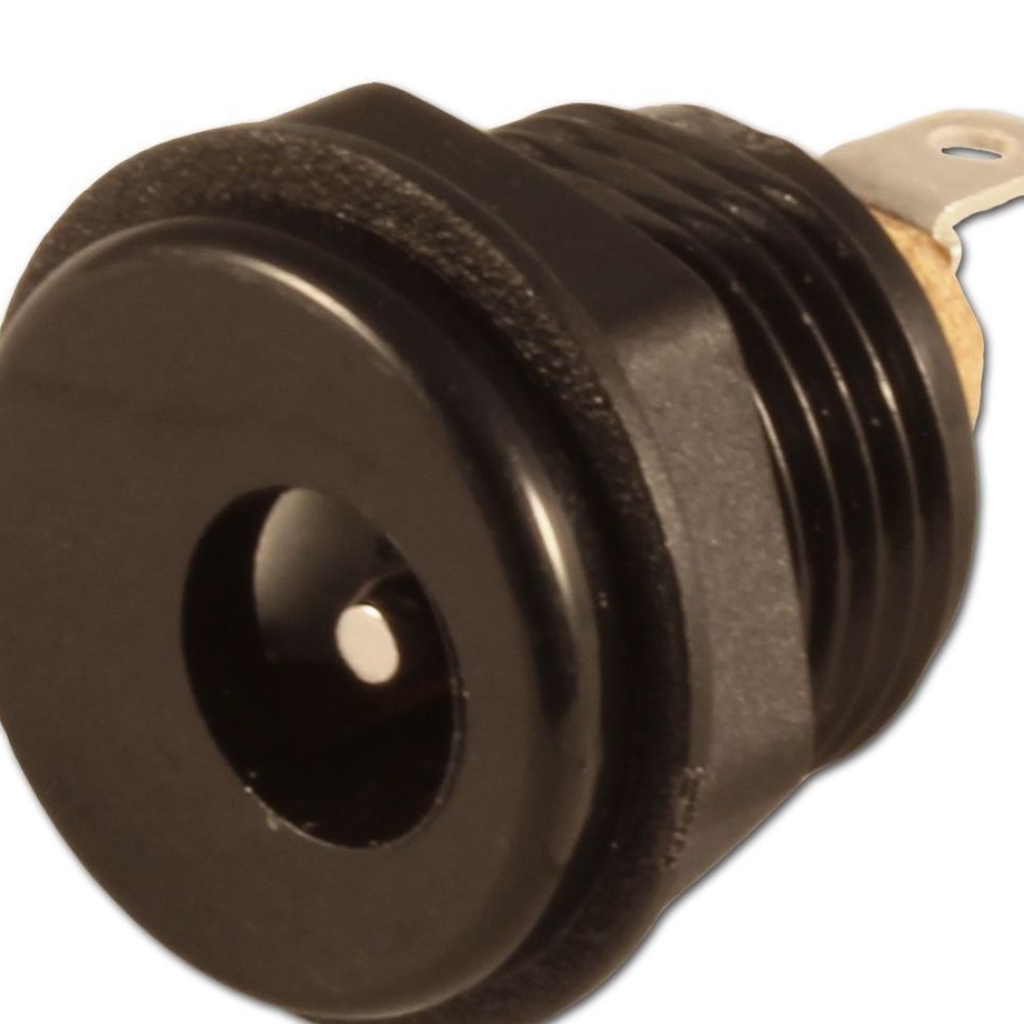
12. Charging connector DC-099 x1 ()
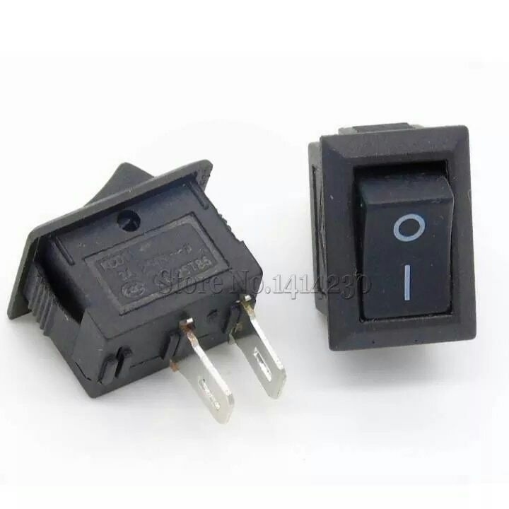
13. Push button switch x1 ()
14. Connecting wires
15. PVA
16.4000uf 16V capacitor
17. Varnish
18. Sealant
19. Sandpaper
20.3 mm LEDs
21. Plywood sheet 18 mm.
22.5 mm plywood
23. M3 and M4 nuts and bolts

Instruments:
1. Screwdriver
2. Soldering iron
3. Saw
4. Sandpaper
5. Rotary tool
6. Glue gun
7. Scissors
8. Pliers
9. A set of drills

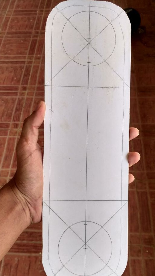
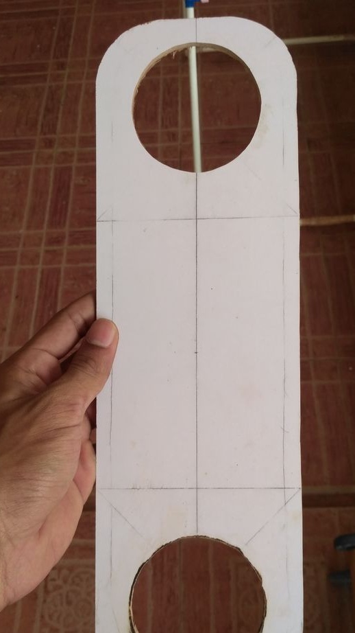
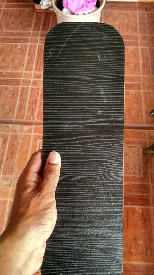
Step 1. Front Panel Design


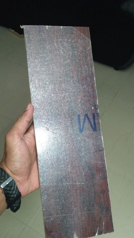
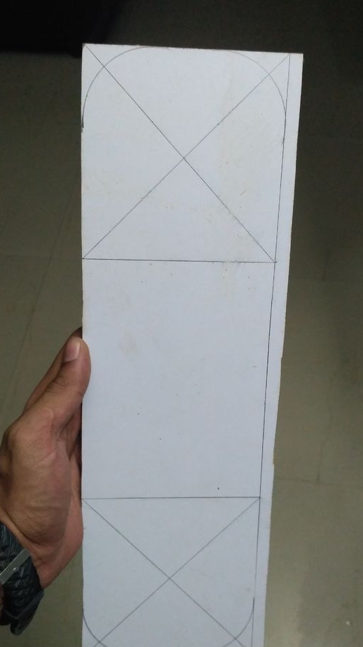
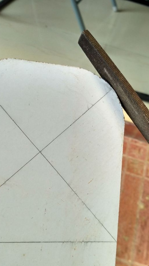
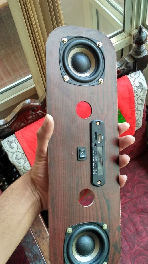
At this stage, the front panel of 5 mm plywood is cut out. On this panel will be mounted speakers, switch, diode, etc. Panel sizes are calculated on 3-inch speakers. The author did not give the dimensions of the panel. The edges of the panel are rounded.

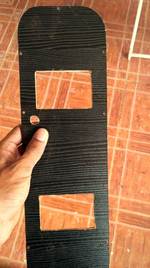
Step 2. Cutting according to the drawing


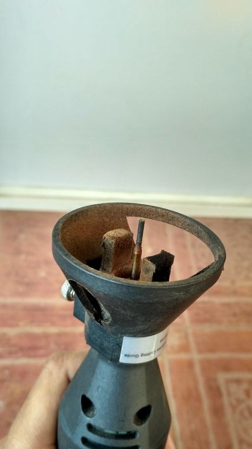
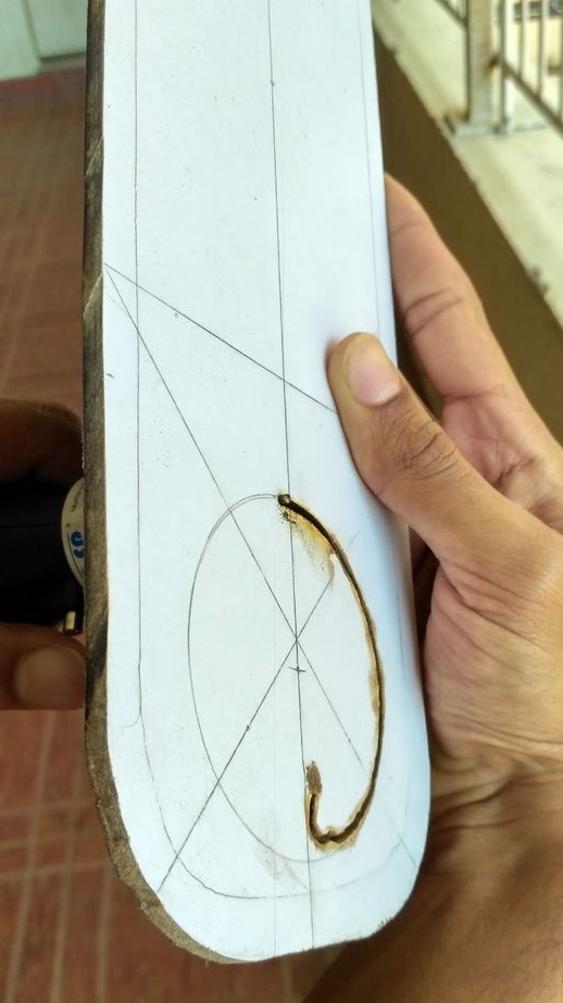
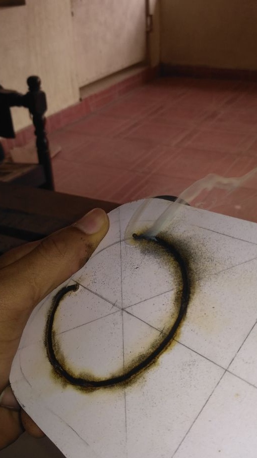
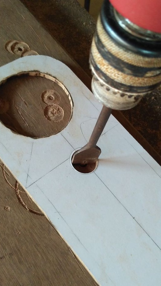
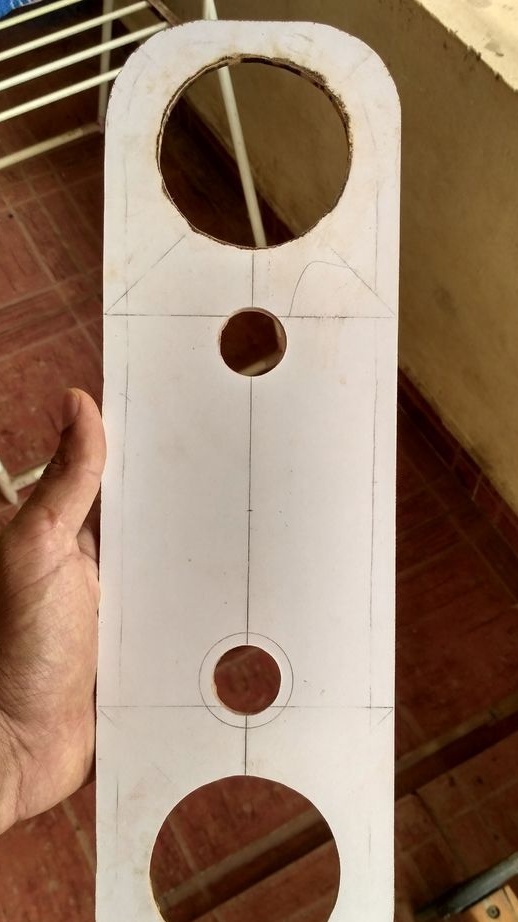
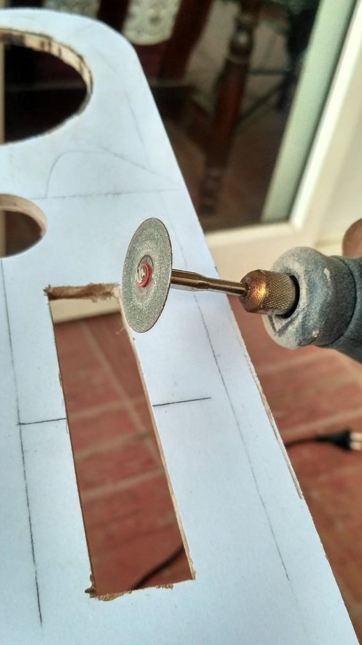
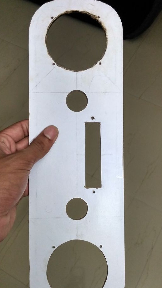
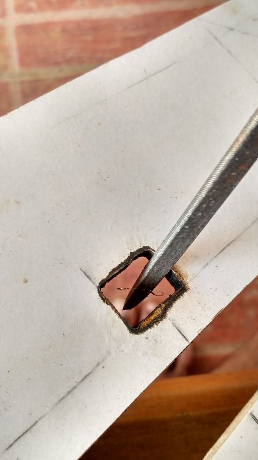
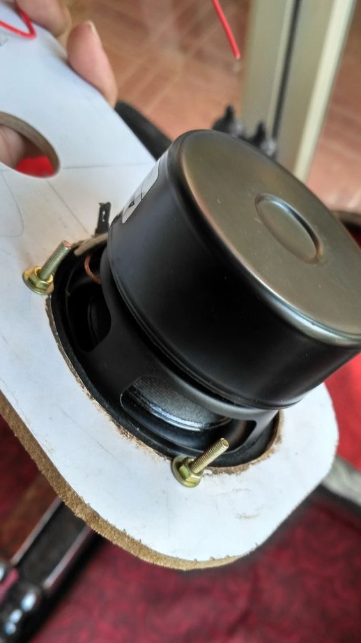
Now putting the cutting bit on the rotary tool, the holes are cut for 3-inch speakers, for 1-inch tweeters, for a decoder in size and for a switch. Then the speaker mount points are marked (they will be mounted on m4 - 3 mm screws) and 3 mm holes are drilled. All holes are filed.

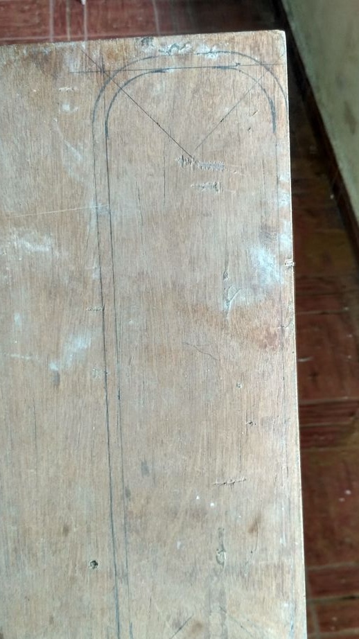
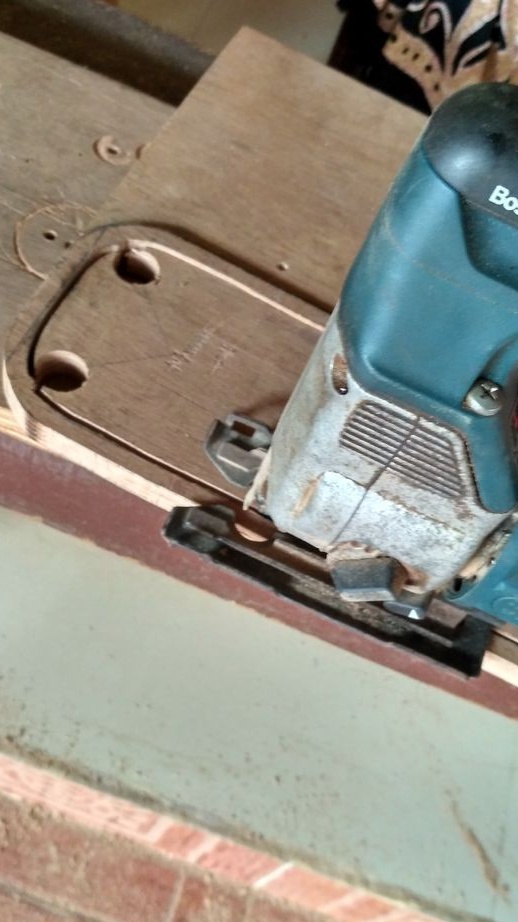
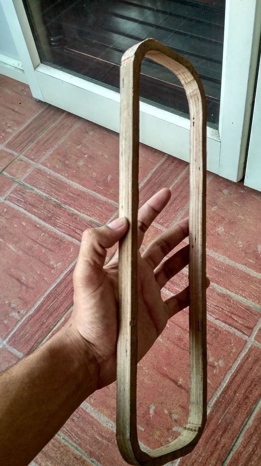
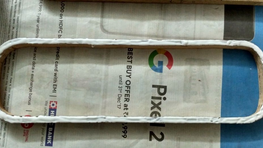
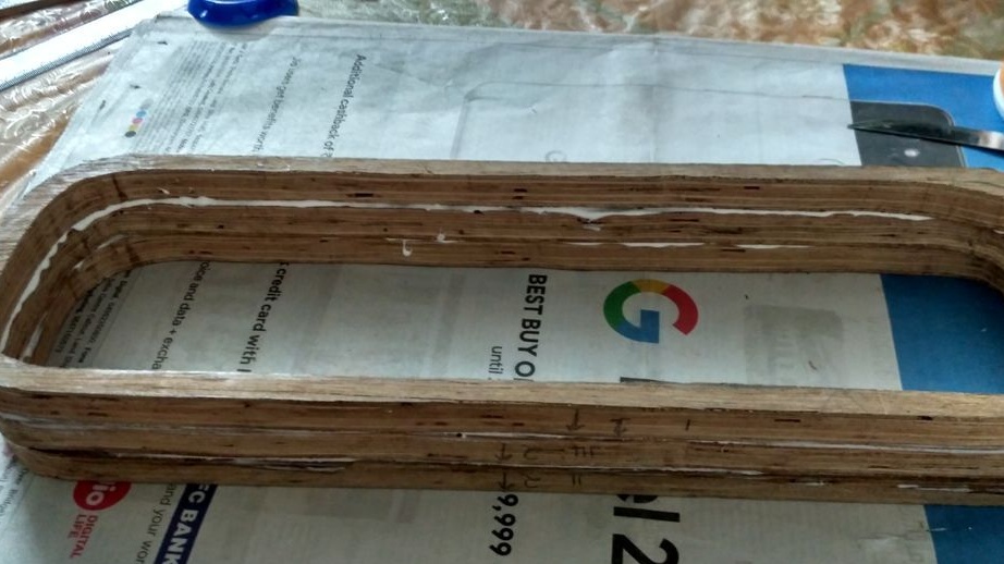
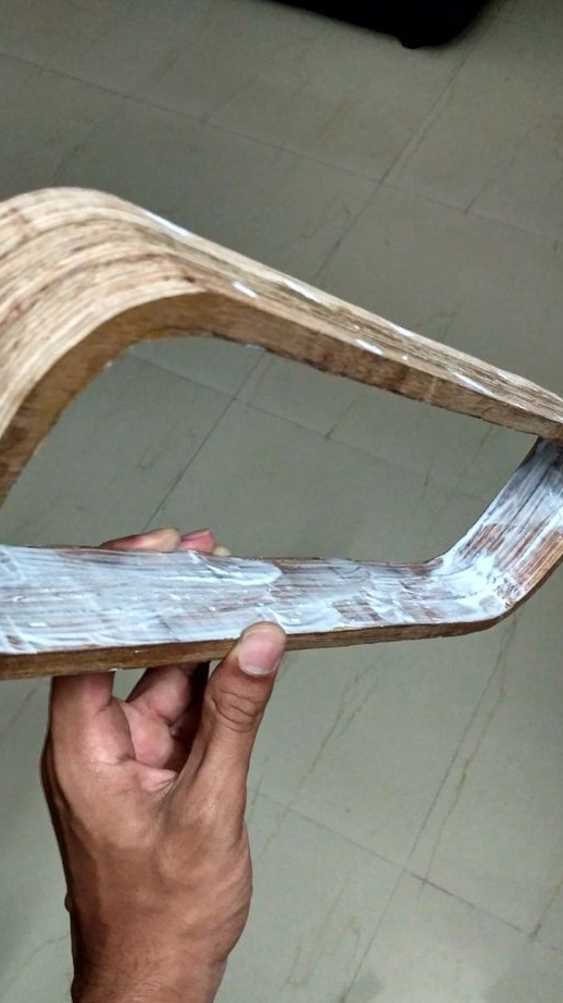
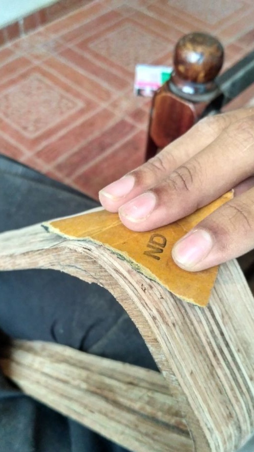
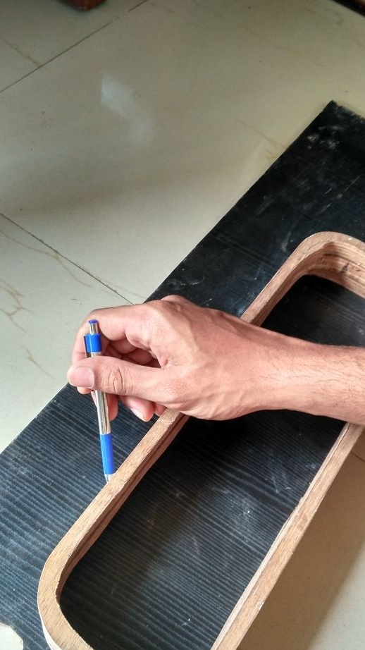
Step 3. Making the case


[/ center]
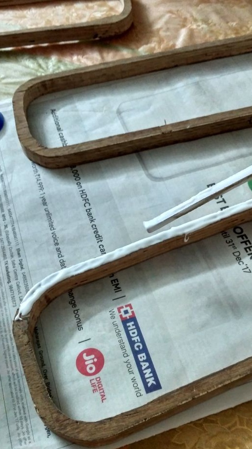
The next step is to put a panel on a 15 mm plywood and draw it with a pencil (the panel should fit tightly into the case). On top of the drawing, another one is drawn at 8 mm distances. And with a jigsaw cut three of these rings. Then all the rings are glued together with PVA glue and left under pressure for the night.After drying, the body is sanded with sandpaper, from coarse to very soft, until you are satisfied with the finish. 3 layers of PVA are applied to the inside and all cracks are closed with wood sealant.

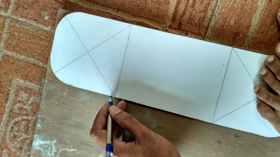
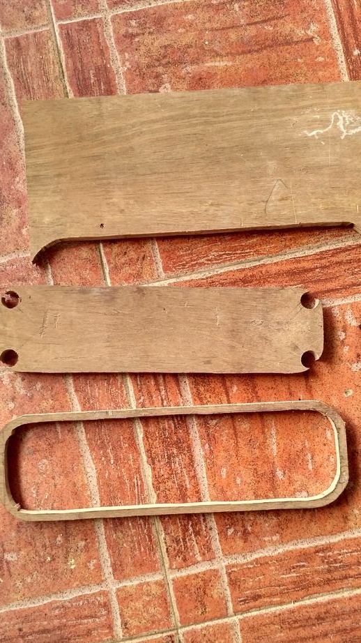
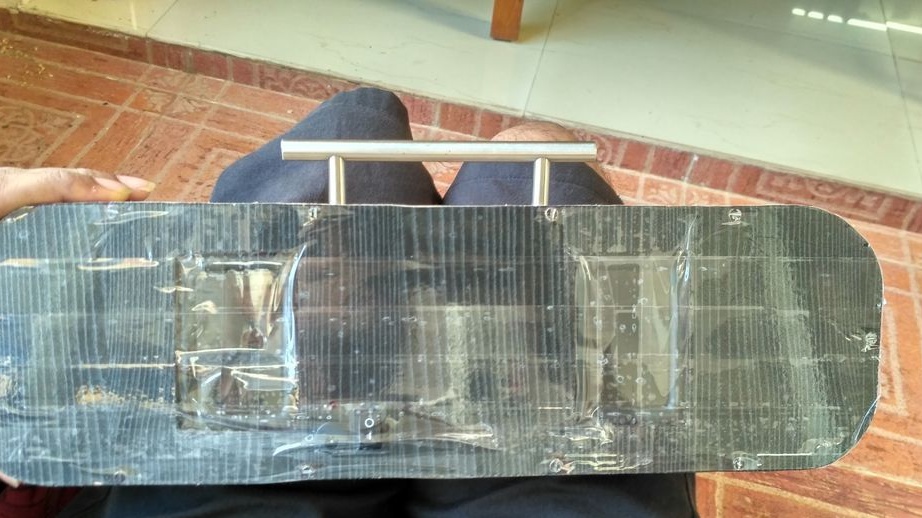
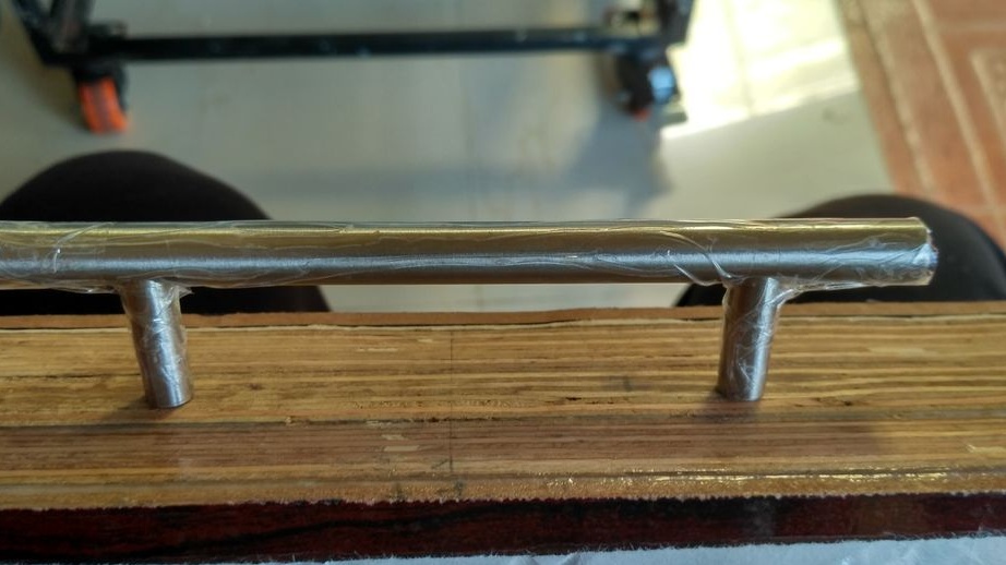
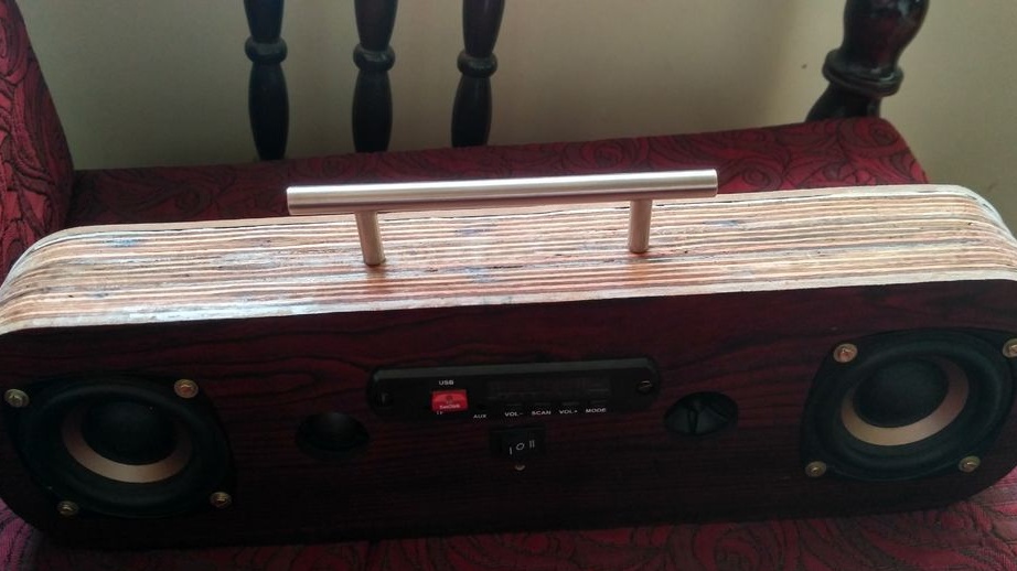
Step 4. Making the back panel and handle


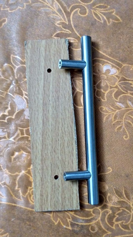
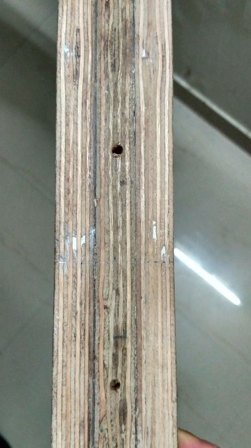
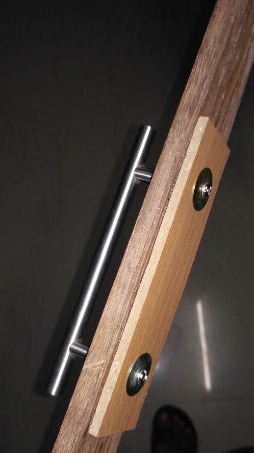
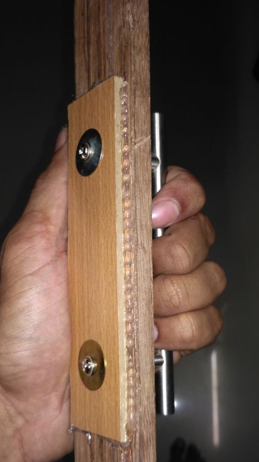
On 5 mm plywood, a contour is marked and cut with a jigsaw. Holes for radiators and power connectors are cut out on the panel. Holes for screws are drilled along the edges. A handle is attached to the housing for convenience.

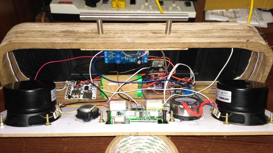
Step 5. Fixing the front panel components


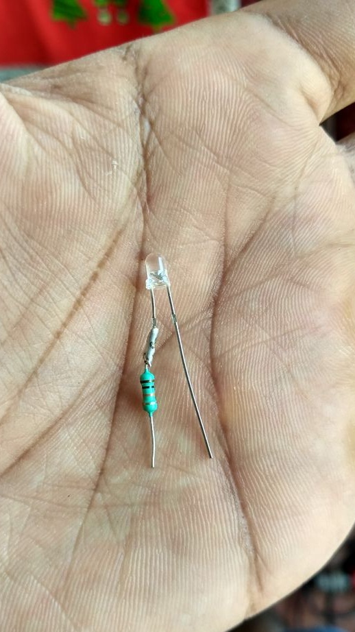
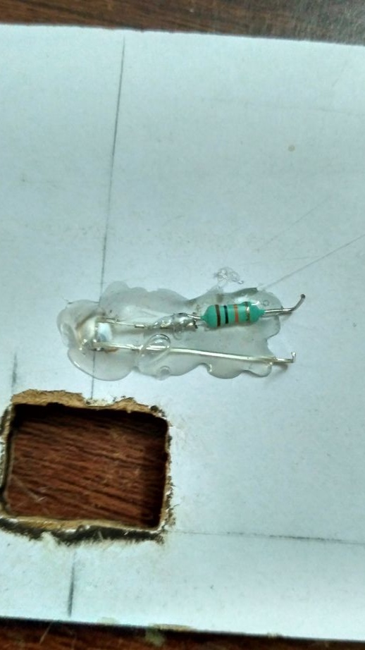
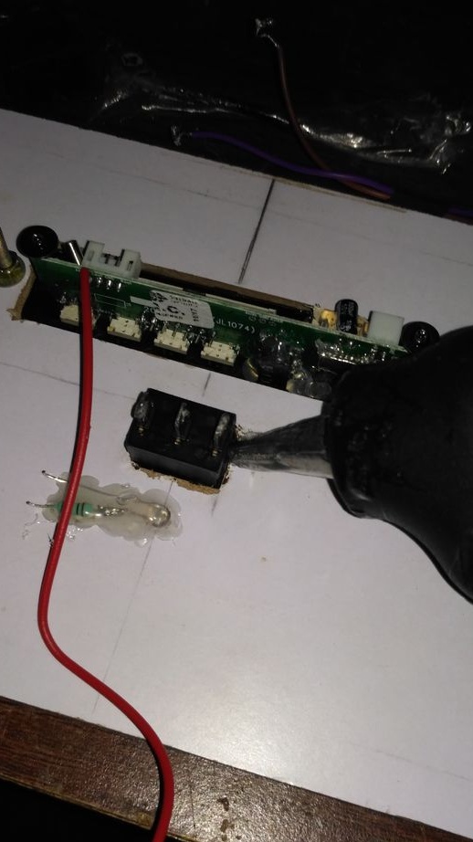
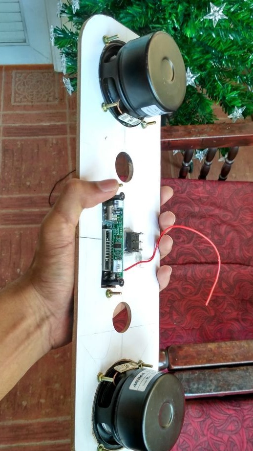
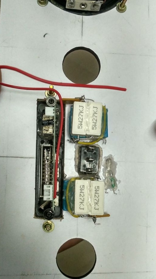
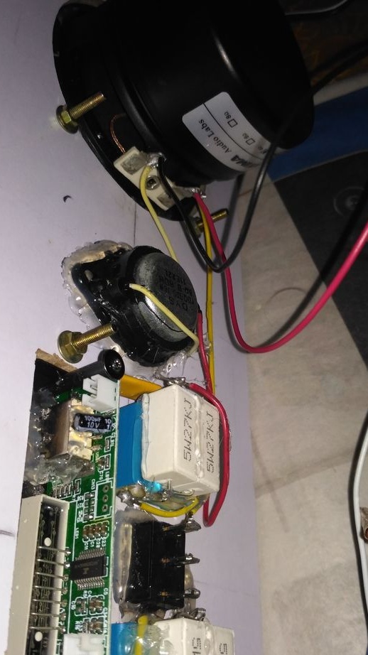
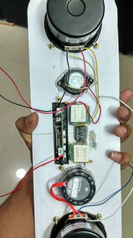
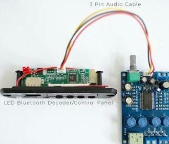
The first step is to attach a power LED with a 10th resistor, hot glue. Then the wires are soldered to the decoder, switch, tweeters and speakers. Speakers connect with tweeters.

Step 6: connection electronic components


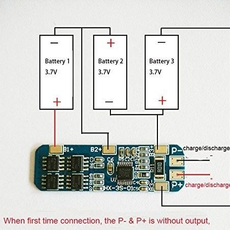
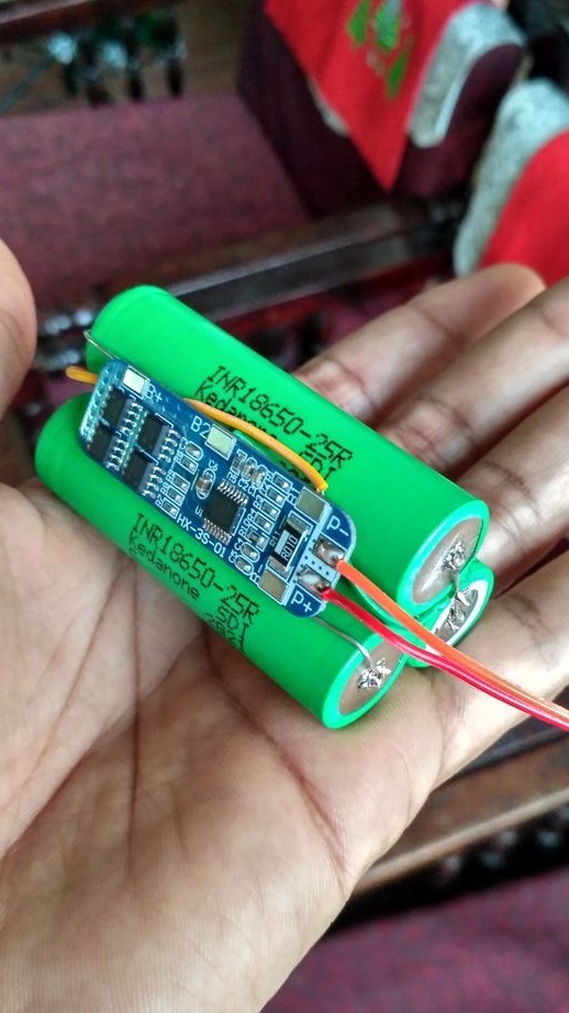
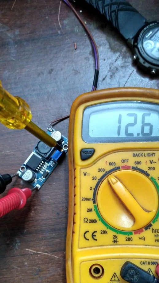
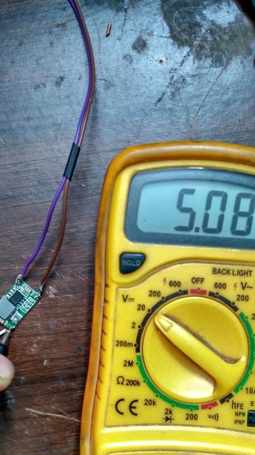
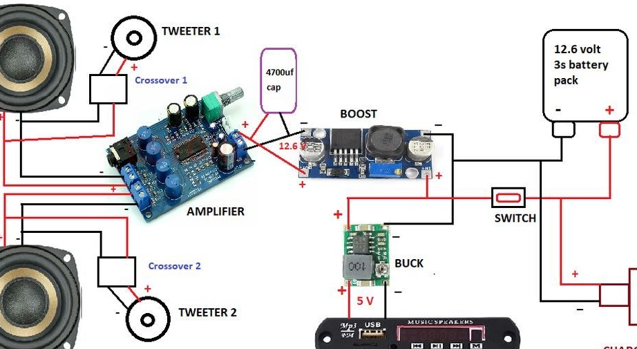
Connecting cells to the BMS in accordance with the electrical diagram. BMS is reset and starts to work only after the charger is connected to the output. Connect a DC-DC boost converter to the battery output (Be careful with polarity). All other components are wired together.

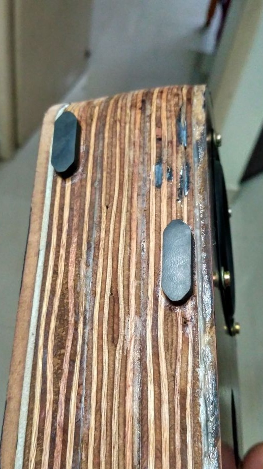
Step 7. Fixing the back panel components


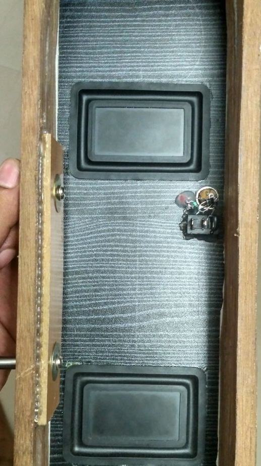
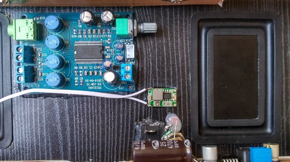
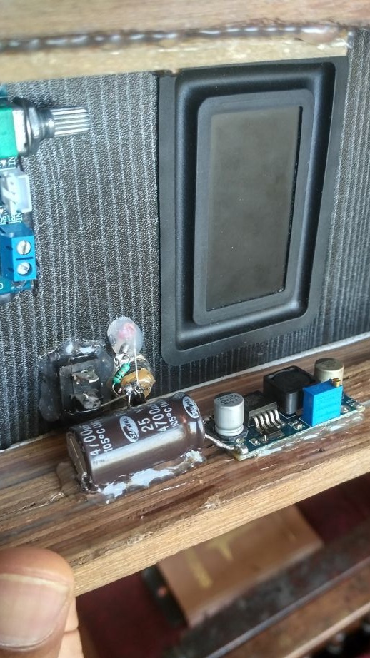
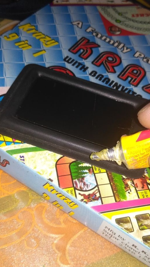
The charging socket is installed in place with glue, just like radiators. The 4700uf capacitor is connected to the output of the boost converter. The remaining components are also placed using glue and connected to each other using wires in accordance with the electrical circuit.

Step 8. Connection of housing elements


When all electronic components are installed and connected, the back and front panels are attached to the body (between the junction of the rear panel and the body you need to glue a thick layer of double-sided tape, this is done for sealing). The front panel is glued with PVA glue.
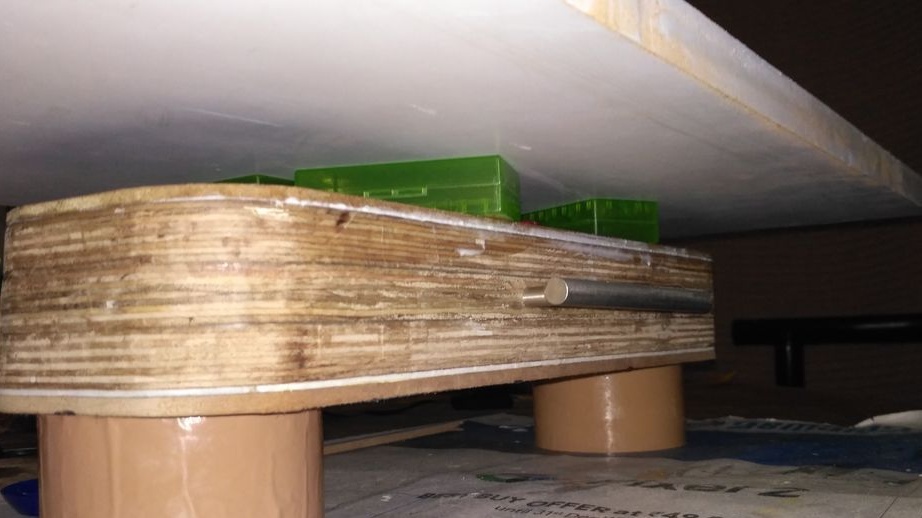
Step 9. FINAL


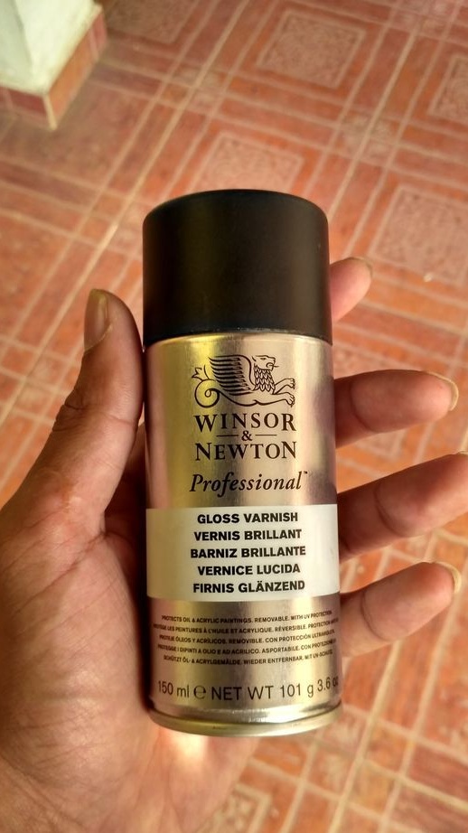
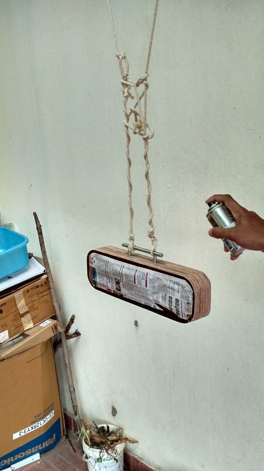
Final grinding is done, the front and rear panels are closed with paper and tape. The remaining part is varnished in 3 layers and four rubber legs are attached. That's all the column is ready. I hope the article is interesting and informative. Thanks for watching, like if not difficult.
8.4
8.4
7.1

Add a comment

    • smilesmilesxaxaokdontknowyahoonea
      bossscratchfoolyesyes-yesaggressivesecret
      sorrydancedance2dance3pardonhelpdrinks
      stopfriendsgoodgoodgoodwhistleswoontongue
      smokeclappingcraydeclarederisivedon-t_mentiondownload
      heatirefullaugh1mdameetingmoskingnegative
      not_ipopcornpunishreadscarescaressearch
      tauntthank_youthisto_clueumnikacuteagree
      badbeeeblack_eyeblum3blushboastboredom
      censoredpleasantrysecret2threatenvictoryyusun_bespectacled
      shokrespektlolprevedwelcomekrutoyya_za
      ya_dobryihelperne_huliganne_othodifludbanclose
26 comments
Of course, it is easy to assemble from the blocks, although even here the author managed to complicate everything with nutrition ... that is a masochist in the body, so if you have time, you can replenish it better. And on the account of the links of the blocks to aliexpress - thank you very much! Always useful ..
- Doctor, I have powerlessness !!!
That is, I climb the first one - normal !!!
... On the second - already shortness of breath !!!
And on the third - I can’t do it at all !!!
- How old are you?
- 70, but what?
- So at your age - that's fine !! I am 50, and then I have only one woman missing !!!
- What women? !!! I'm talking about STEPS !!!!


.
The capacitor is connected in series with the squeaker. No objections? Not.))
The resistor can be switched on either in series with the capacitor, or in parallel with the speaker. In the first case, these are units of ohms, in the second, most likely, of the order of 10 ... 20 ohms. Specific values ​​depend on the crossover frequency and the sensitivity of the woofer and tweeter. In most simple two-way speakers, the isolation filter is just one capacitor, without unnecessary fantasies.
And the kilo-ohms in the dynamics chain in products like this one have nothing to do.
[quote] [Ohm units - what for do you need a capacitor? / quote] Are you serious? At break, in the kilohertz range?
Quote: Ivan_Pokhmelev
What is clear, then? 13 kilo-ohms in a low-resistance circuit - delirium and absurdity. It would be there units or tens of ohms - could be discussed. Then 5 watts would not look so ridiculous.

Units Ohm - what for then do you need a capacitor? The bottoms will try to tear off the diaphragm. laugh1
Dozens of hells are a vague topic. smiles
Kiloomes - so then you can only blame it on a brutal look, and call it not just a capacitor, but call it something more scientifically-weighty. fool
(From the talk of pensioners on the bench) ....
Yeah ... so she came, senile weakness, I used to bend him with two fingers, and now I won’t bend with both hands! smile
(From the talk of pensioners on the bench) ...
Quote: Subbota40
The RC chain is sequentially tweeter. Cuts mid and low frequencies. With this, it is somehow clear.
What is clear, then? 13 kilo-ohms in a low-resistance circuit - delirium and absurdity. It would be there units or tens of ohms - could be discussed. Then 5 watts would not look so ridiculous.
Ehhh ... Time .... Where are you flying? !! ..
... It used to be five sticks a night - and fine !!! ..
And now?!!!..
... one, two ...
And that’s all !!! ... The hand falls off !!! ...
(From the talk of pensioners on the bench) ....
xaxa
Okay. The RC chain is sequentially tweeter. Cuts mid and low frequencies. With this, it is somehow clear.
But why are 5-watt ceramic wire? Where does so much energy come from that must be dissipated into heat ???
I'm in stupor.
The author is either a non-epic genius or does not quite understand electronics. Well, or in electricity. smiles
Quote: Korolev
Nah, they are there in parallel!
This, of course, significantly changes the matter.))))
27 kOhm at the output of the amplifier - that's it. )))
Nah, they are there in parallel! smile
27 kOhm at the output of the amplifier - that's it. )))
Quote: Subbota40
This audio decoder is sold for 12v power (with an already built-in stabilizer). In the presented photo, in the left corner, the stabilizer chip 7805 is clearly visible.

You correctly noticed that, moreover, if you follow the link, then there are 12 V directly in the name. So you found one more cant.
Quote: Subbota40
The boost converter is generally beyond my comprehension. The load current will reduce, the output voltage is also like 12V. With 12 volt power and without it, you can swing these speakers pretty well.
The first and third are absolutely true.
On the second point. In the converter, in general, the difference between the output and input voltage is not normalized, but according to indirect data (at extreme values ​​of the supply voltage), we can conclude that it is not less than two volts. With fully charged batteries, the output of the converter cannot be less than 14.6 V, and the ULF has a maximum allowable supply voltage of only 14 V. So, in addition to reducing the efficiency, this converter also reduces the reliability of the ULF. In addition, since the voltage of the ULF is normalized from 9 to 14 V, powering directly from the battery provides additional information about its discharge: at a voltage of less than 3 V per cell (which is close to the minimum acceptable value), the sound will deteriorate, which will signal that the battery it's time to charge.
All all all ... Humbly apologize.
Even at work, doctors do not always interpret this diagnosis so clearly.
Okay. I don’t climb into a strange monastery with my charter.
I undertake to continue to voice this diagnosis only applicable to myself and my crafts.
The author put a solid five for craving for masturbation. He himself has been ill with such a life.
This intimate topic has already been discussed!
MASTURBATION
Same as masturbation.

Cloak - cf. out of date. Irritation of the genitals with hands to satisfy the sexual instinct; masturbation. Explanatory Dictionary of Ephraim. T.F. Efremova. 2000 ... The Modern Explanatory Dictionary of the Russian Language Efremova
The author put a solid five for craving for masturbation. He himself has been ill with such a life.
Creation turned out in C grade.
The idea is not new, execution does not shine with accuracy, practicality and design.
But, the author did it for himself. He likes it and it suits him. No need to judge strictly.
Any homemade product is a stepping stone in personal growth.
Well done in general. Train further.
The aliexpress module could have been voiced. I built a couple of these into wooden active speakers. Cool stuff.
As for repetition, Duc is not an end in itself. It’s difficult to repeat my homemade products, and many people find it very difficult.
I did not understand why a boost module is needed and why a 5-volt stabilizer on a separate board.
This audio decoder is sold for 12v power (with an already built-in stabilizer). In the presented photo, in the left corner, the stabilizer chip 7805 is clearly visible.
The boost converter is generally beyond my comprehension. The load current will reduce, the output voltage is also like 12V. With 12 volt power and without it, you can swing these speakers pretty well.
impregnated with epoxy resin or PVA glue,
This is already, if not fiberglass, then not paper mache! And I'm talking about paper in its purest form, although you are certainly right!
In vain, ironic, toilet paper impregnated with epoxy resin or PVA glue is an excellent material for forming complex cases. I glued on the matrix from the toilet paper of a boat for a model of a sailboat, it looks good.
some RC chains with strange denominations.
Sleight of hand and no fraud! The values ​​of the resistors ??? smile
Well, as you do not understand, this is a piece of art =)
I will continue:
4. The photo shows that the BMS board is not connected to the intermediate points of the battery. He specifically turned to the source - and there it is not.
5. In the figure, imitating the circuit, one switch, in fact - two.

You can go on, but it makes no sense. Just as it makes no sense to put here such "creations" that do not carry anything new, are full of errors and are categorically not suitable for repetition.
What I liked: the author made his garbage a simple tool, without using a dozen expensive machines.
I did not like it, except for the previously indicated:
1. The design is not collapsible, but inside all the components are stuck with thermal nozzles.
2. There is some card reader in the photo that is not reflected in the text.
3. Speakers and passive drivers are not protected against damage.
To build a radio designer
Of course, I apologize, but, in my opinion, you can not discount toilet paper! smile
To assemble the radio constructor from the finished Chinese modules, I propose material for the case:
1. Polyfoam
2. Polycarbonate
3. Papier mache
4. Pallet
5. Plexiglass
etc. everything that can be glued, knocked down, twisted with screws.
Passive radiators
But really what?
In the list of crossovers, in fact, some RC chains with strange denominations. ((
The boost converter will not work normally with an output voltage of 12.6 V. And in general - why is it? Efficiency lower?

We advise you to read:

Hand it for the smartphone ...