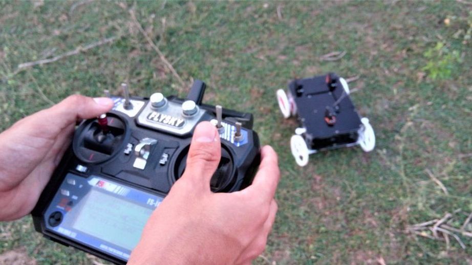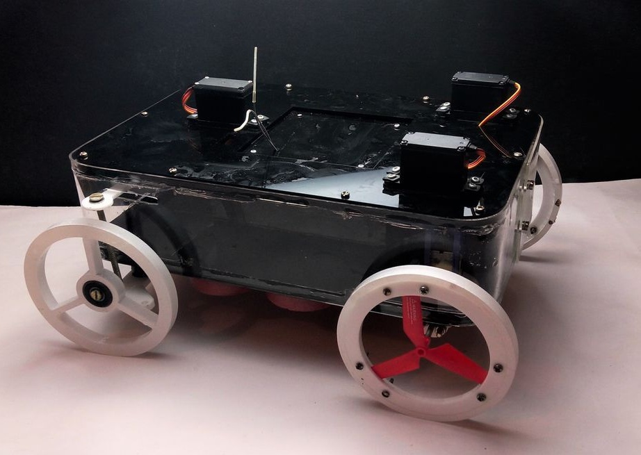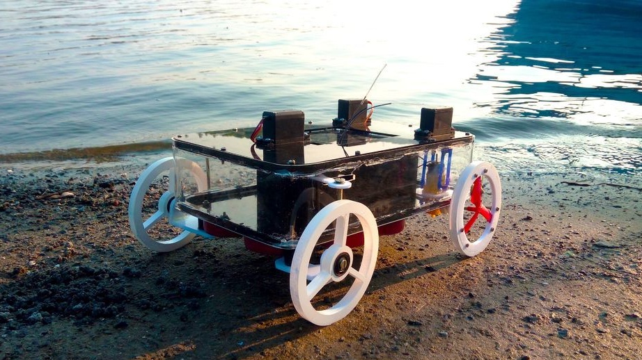
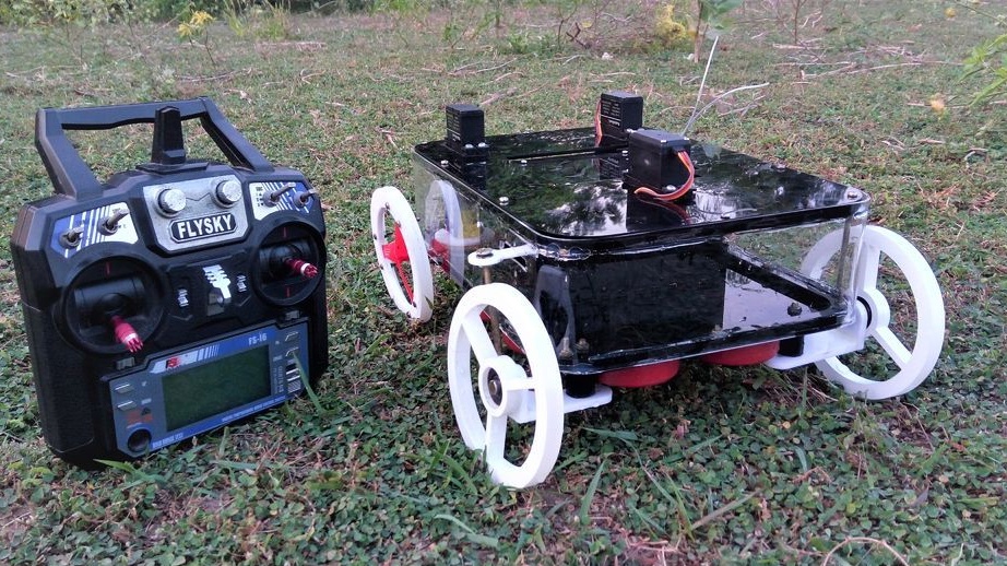
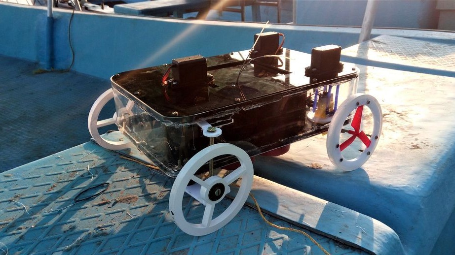
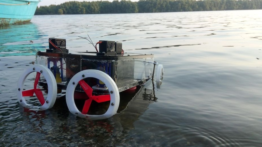
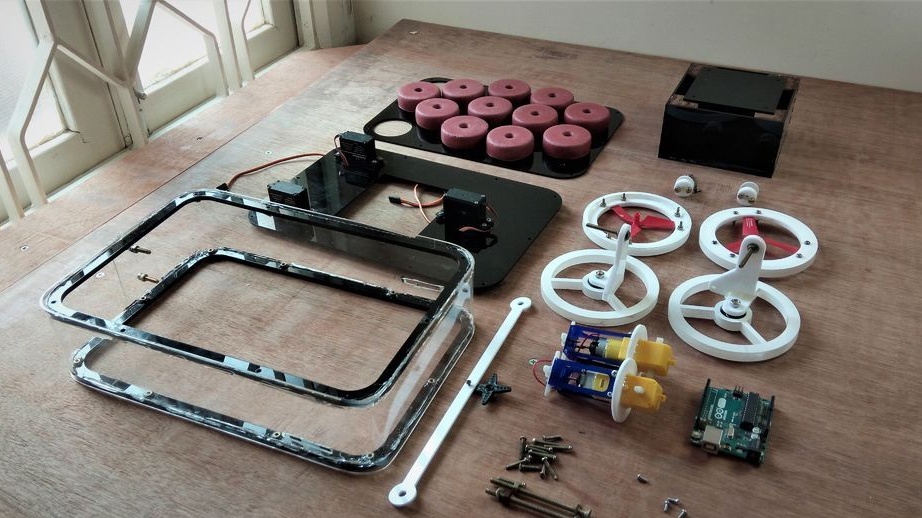
In this article, we will consider the manufacture by Indian craftsmen of an all-terrain vehicle moving both on land and on water. All terrain vehicle consists of a floating platform with wheels and a propeller. Mechanisms are controlled by remote control via Arduino UNO.
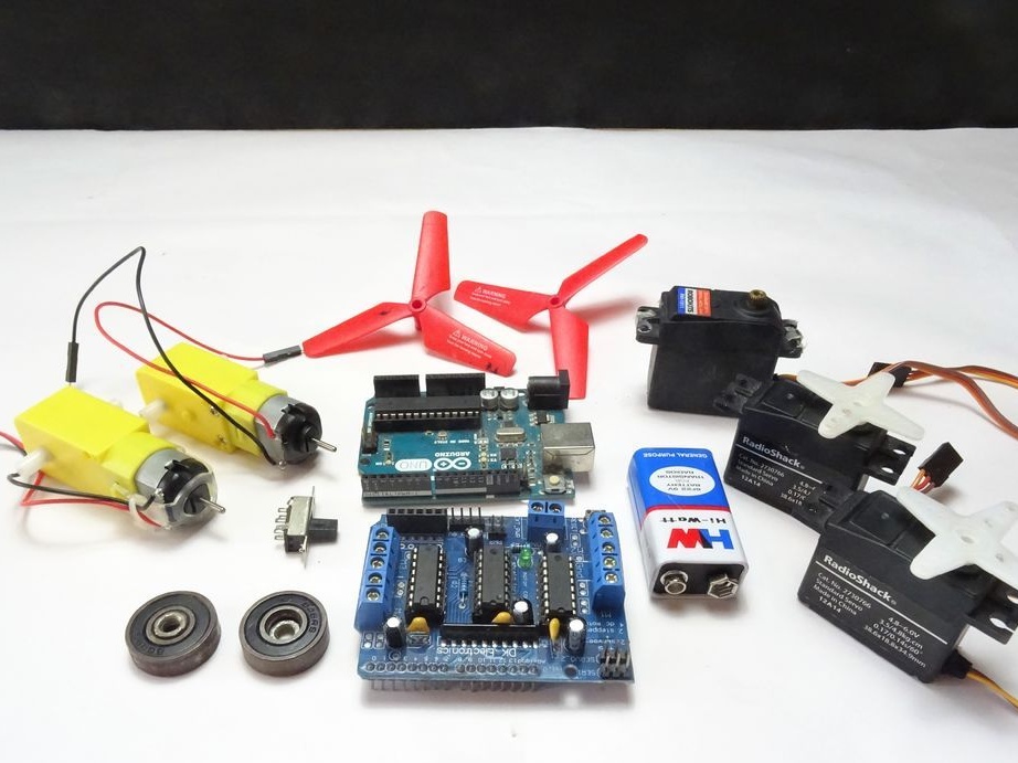
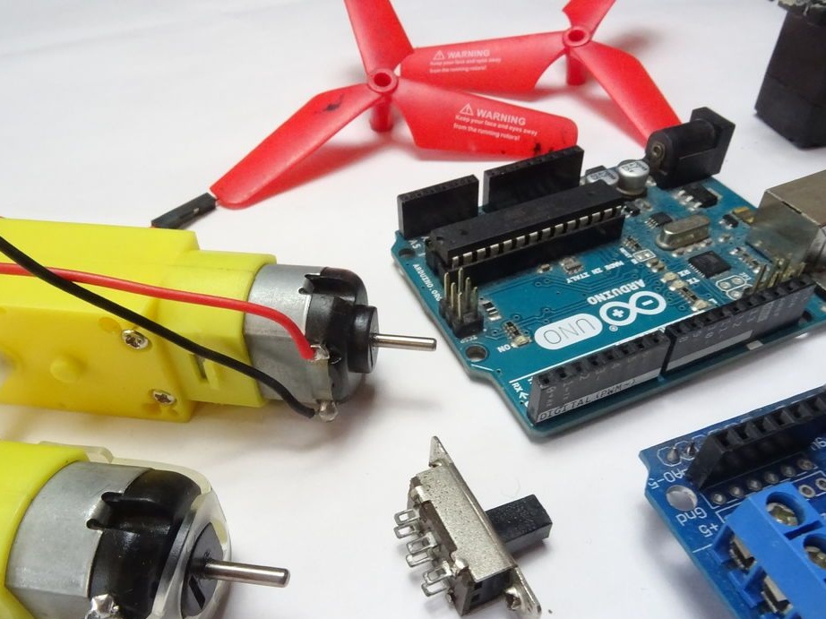
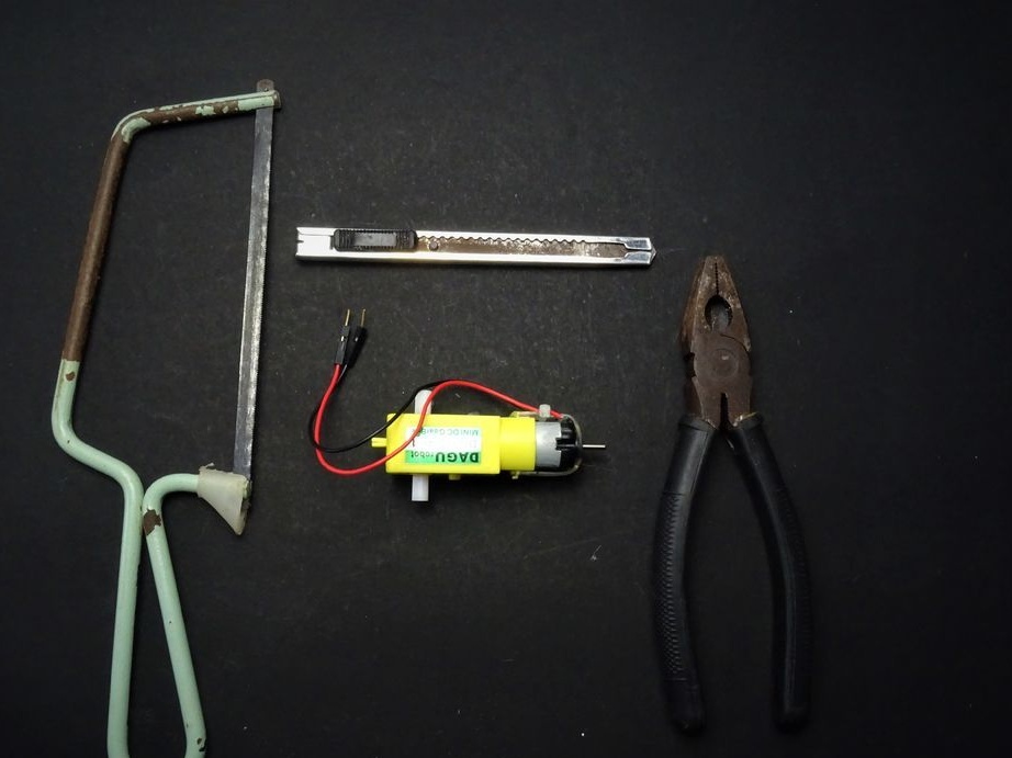
Tools and materials:
-
-AKB 9V;
-Switch;
-Acrylic;
-Plywood;
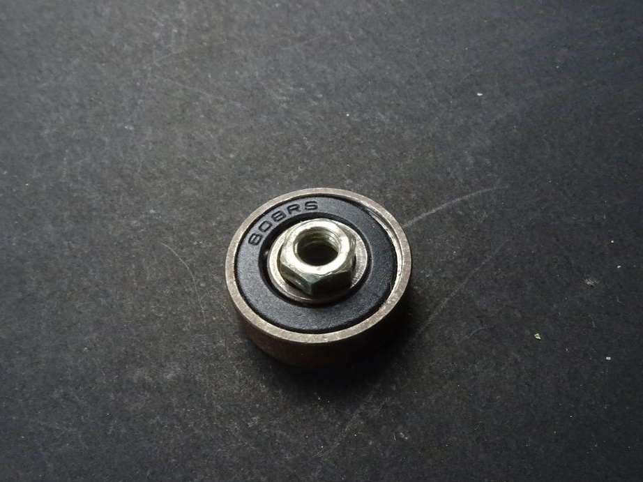
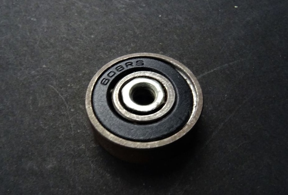
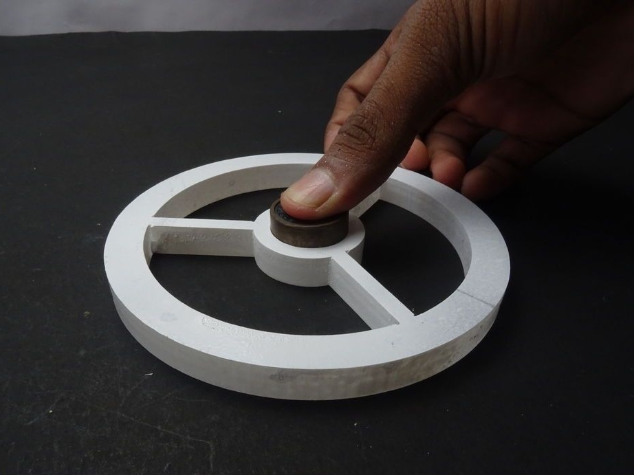
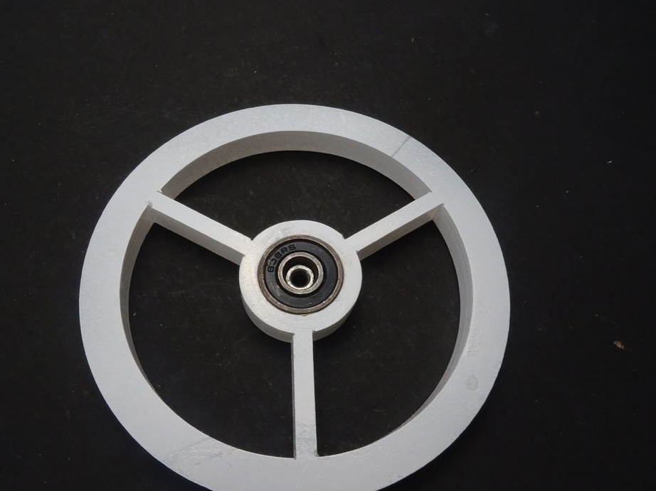
(by reference, the bearing is 8 x 16 x 5 mm, the author indicates 8 * 22 mm)
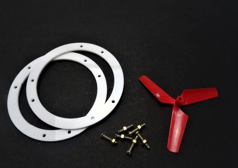
-Two propellers;
-Fasteners;
-Floats;
-Glue gun;
-Super glue;
Epoxy resin;
-Soldering iron;
-Drill;
-Laser cutter;
-Saw;
-Screwdriver;
-Drill;
-Soldering iron;
-Board;
-Computer with software;
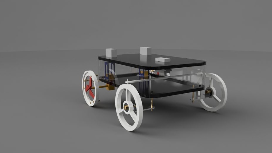
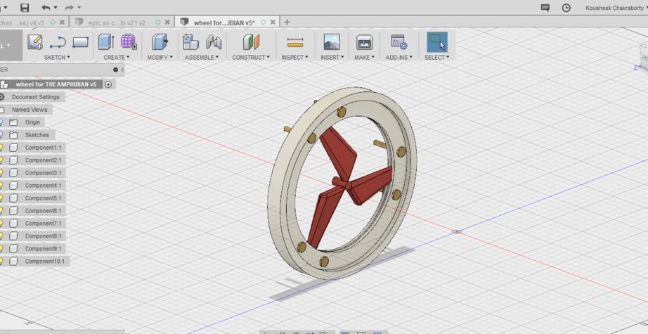
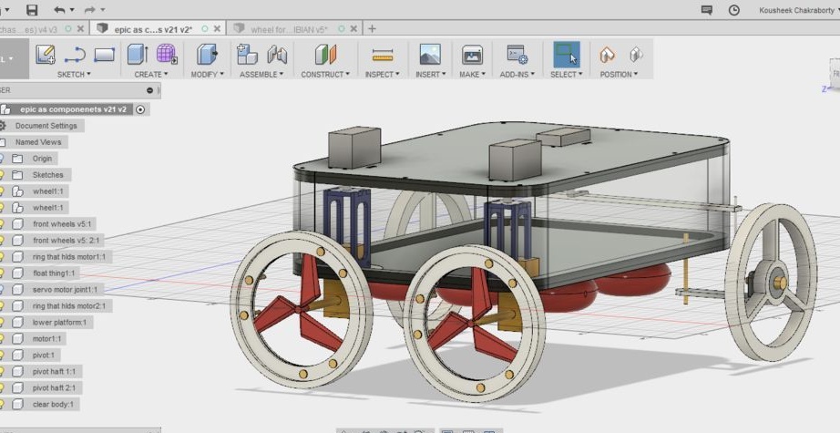
Step One: Design
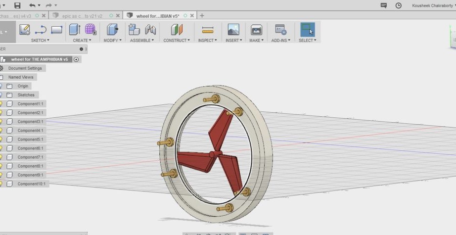
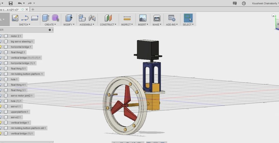
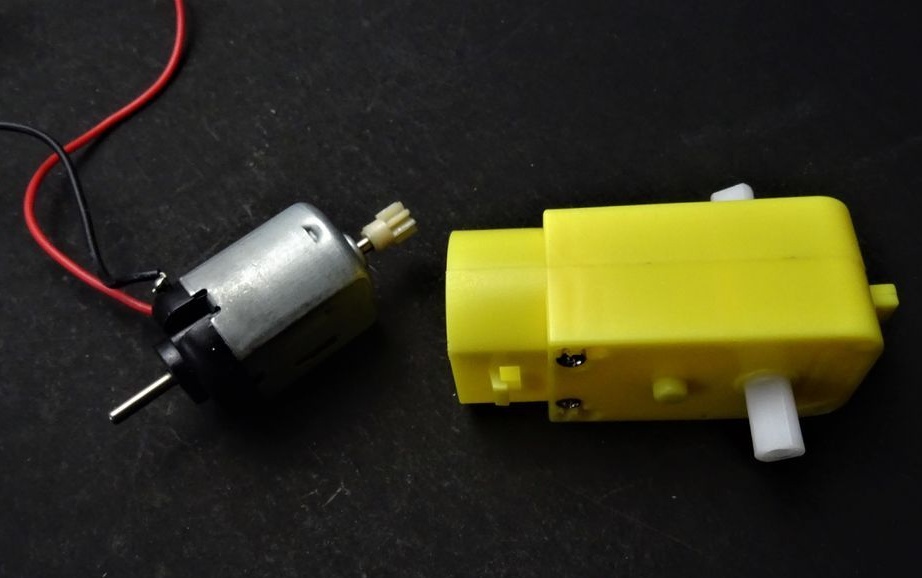
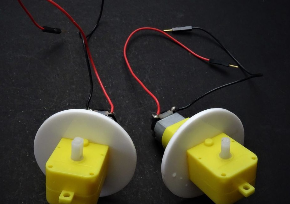
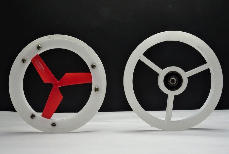
To create the project, the masters used the Fusion 360 program. The whole difficulty was to combine movement on land and in water. When designing the wheels, the masters developed a system in which the screws would open in the water, but in view of the complexity of the design, they simply integrated the propellers from the children's toy inside the wheel. This allows the wheels to move the all-terrain vehicle on land, and when they enter the water, the screws are turned on.
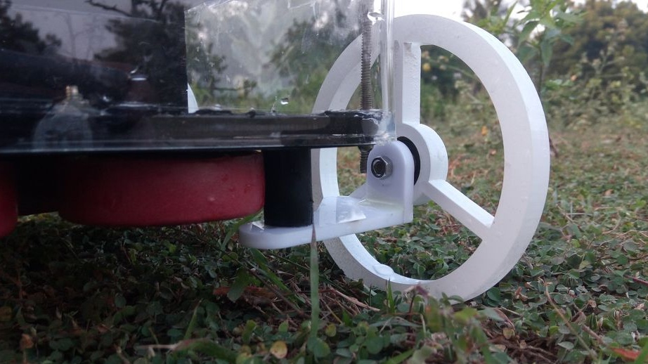
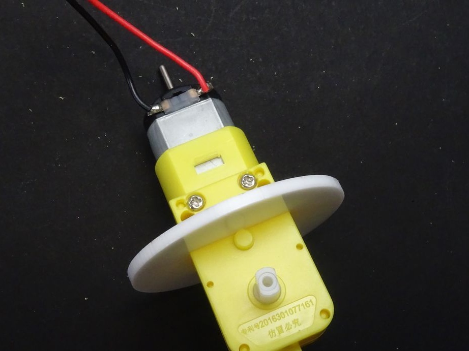
To implement this idea, you need to be able to rotate the rear wheels perpendicular to the all-terrain vehicle when driving on water. This became possible when engine gears were taken out of the frame. Plastic gearboxes and water entering them will not harm.
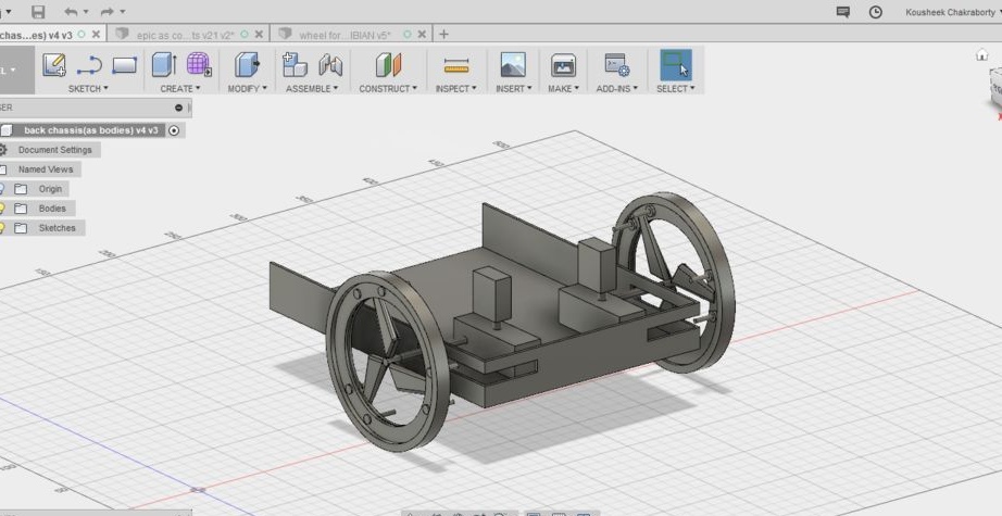
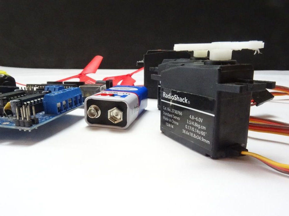
The rotation of the wheel-screws will be carried out using a servo drive.
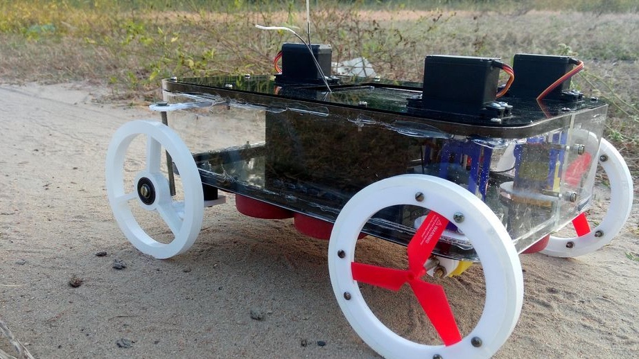
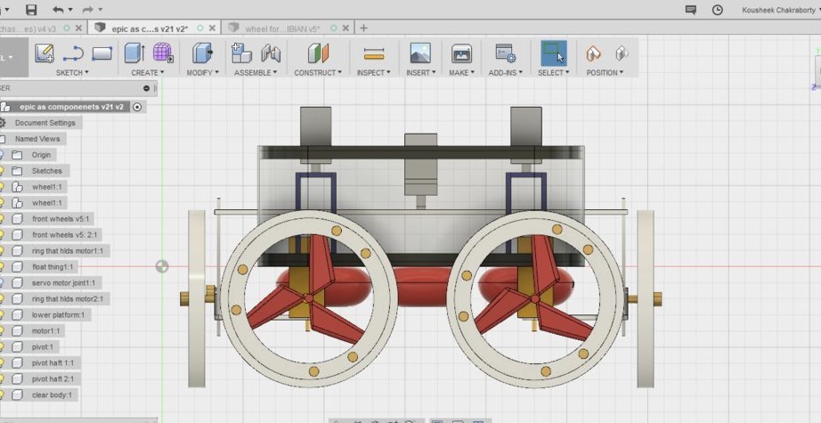
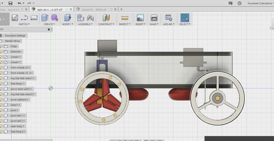
The all-terrain vehicle has two turning mechanisms. One to control the rear wheels of the propellers in the water, and the second, to drive on land, controls the front wheels. The angle of rotation of the front wheels is 35 degrees, which allows you to make sharp turns.
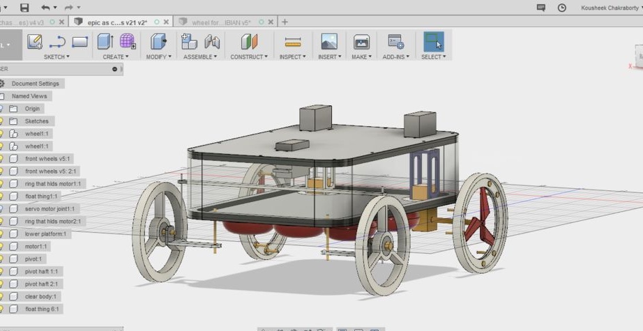
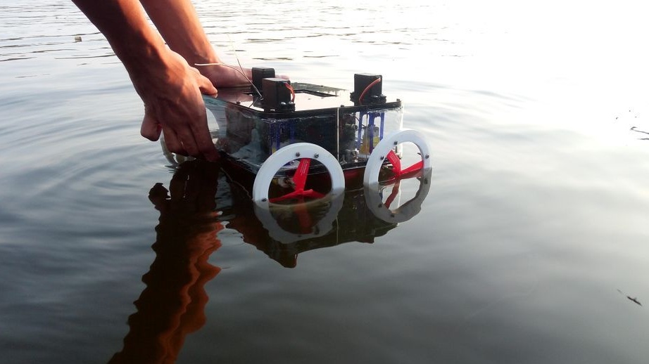
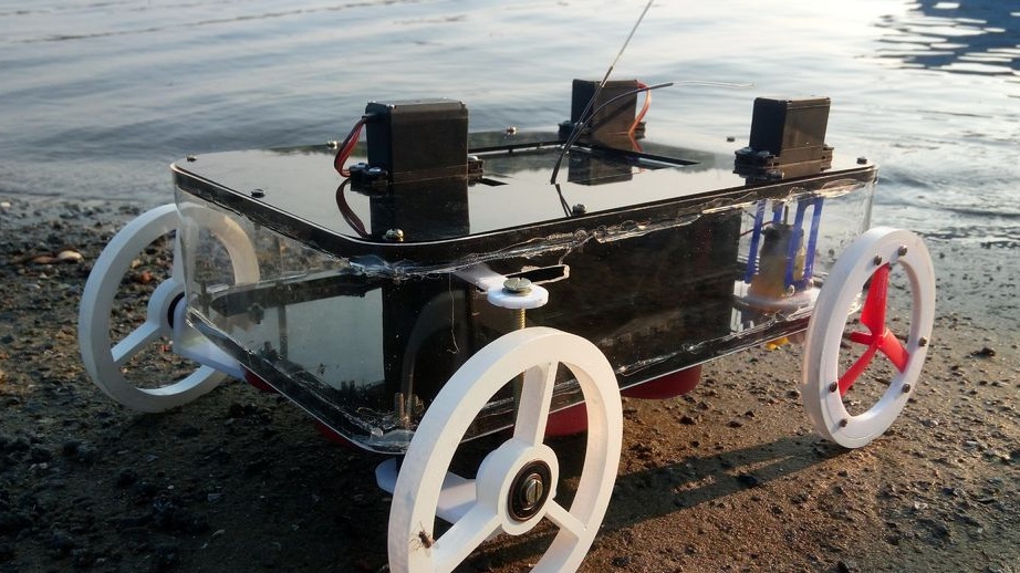
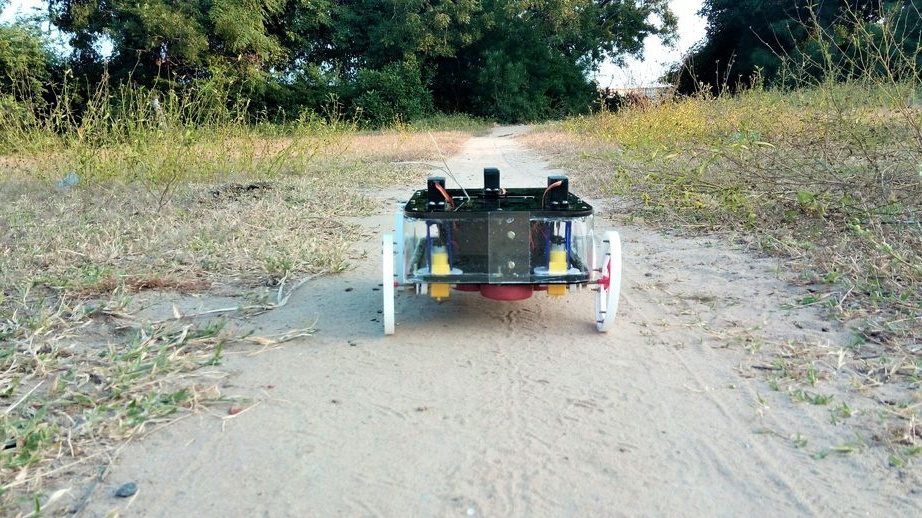
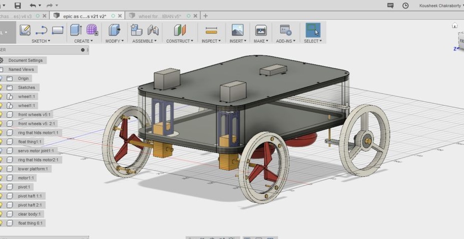
In the pictures below you can see the transformation of the all-terrain vehicle when moving through land and water.
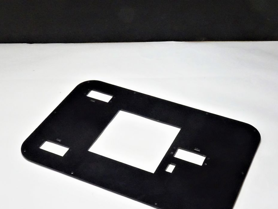
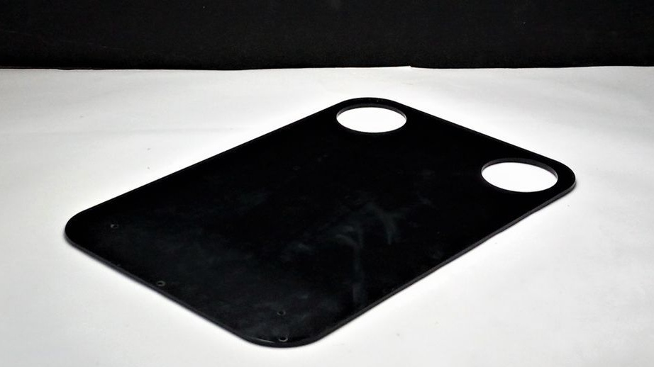
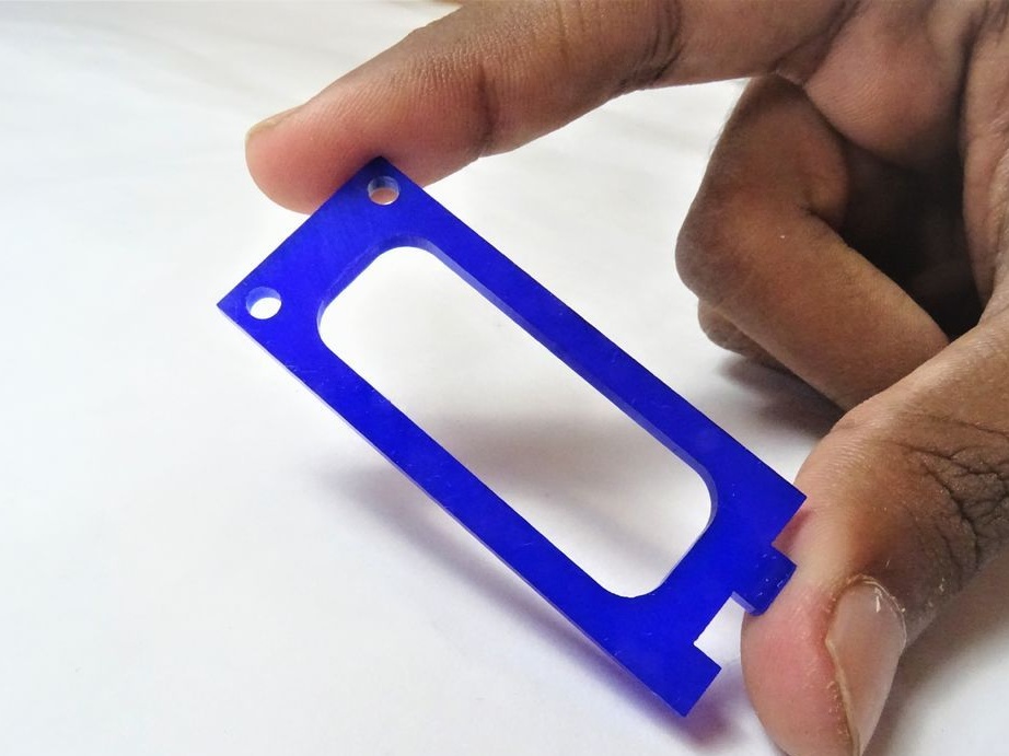
Step Two: Laser Cutting
For the all-terrain vehicle, the master used acrylic of different thicknesses and colors.
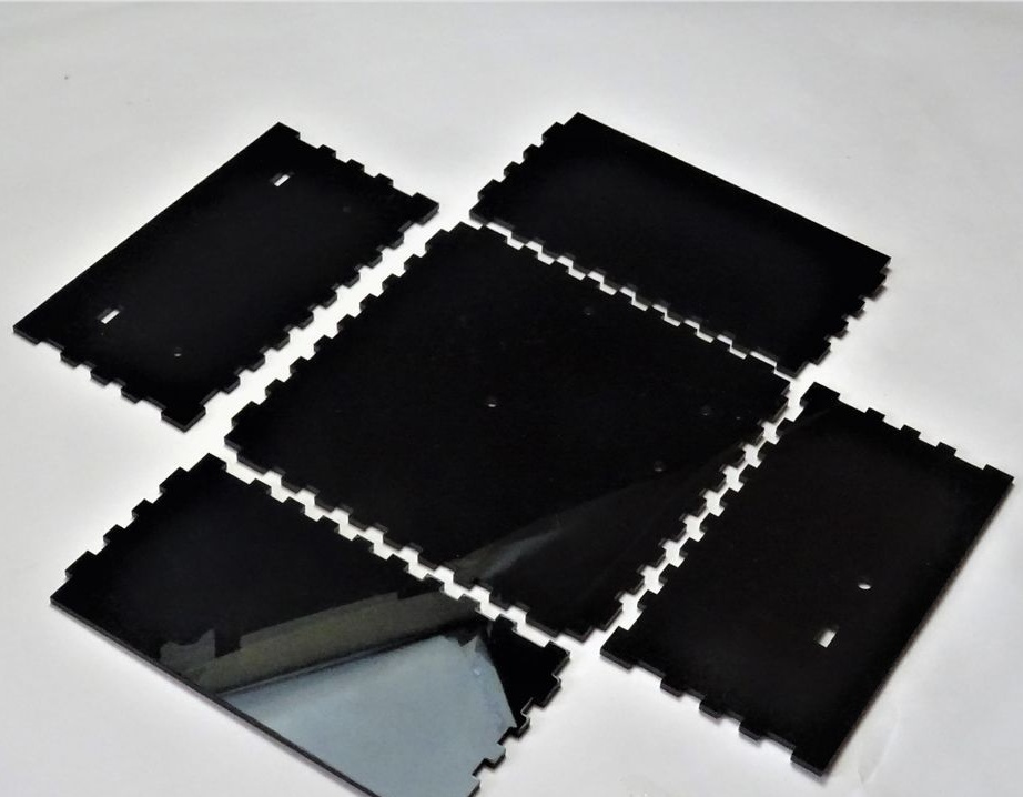
Black top coat 3 mm x 1
Bottom Layer Black 3 mm x 1
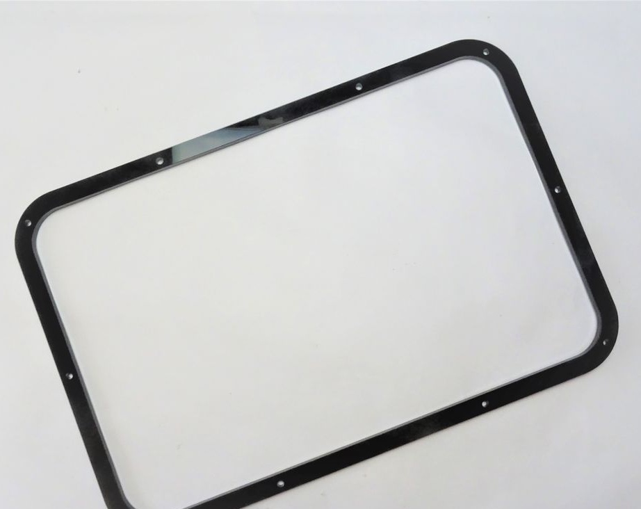
Black side frame 5 mm x 2
Side wall transparent 2 mm x 1
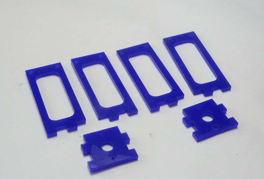
Power side blue 3 mm x 4
Bridge Top Piece Blue 3 mm x 2
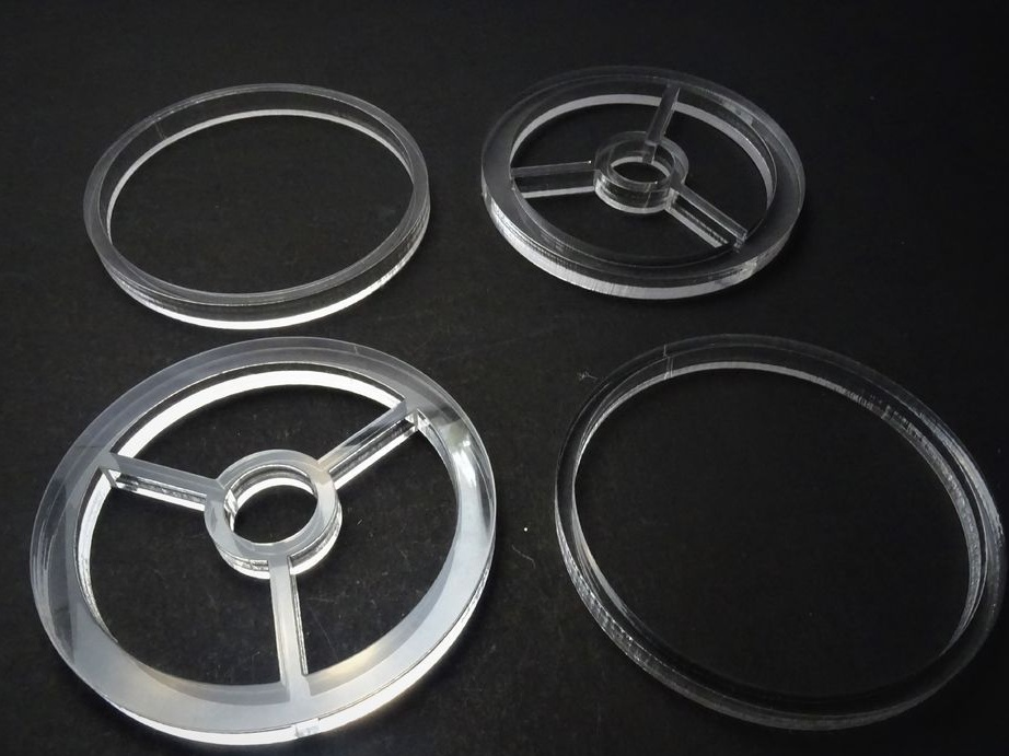
Engine DisK White 3 mm x 2
Front wheel white 10 mm x 2
Inner Rim (Rear Wheel) White 3 mm x 4
Outer rim (rear wheel) White 10 mm x 2
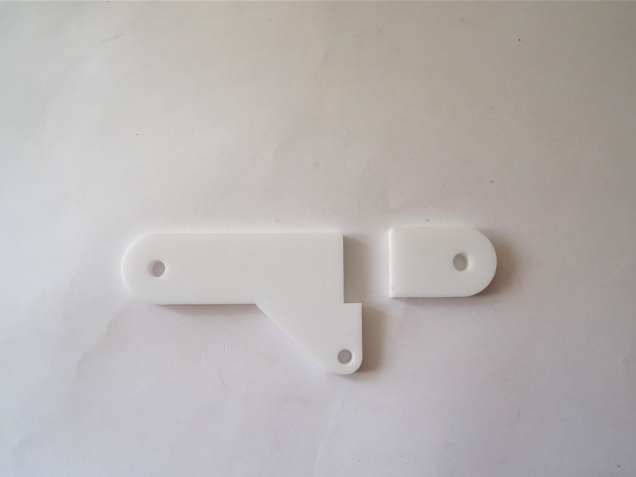
Steering White 3 mm x 1
Drawer cabinet Black 3 mm x 1
Black compartment cover 3 mm x 1
Rear motor shaft White 3 mm x 2
Front panel white 5 mm x 2
You can download the file for the CNC from the link.
Laser Cutting Rover Parts.zip
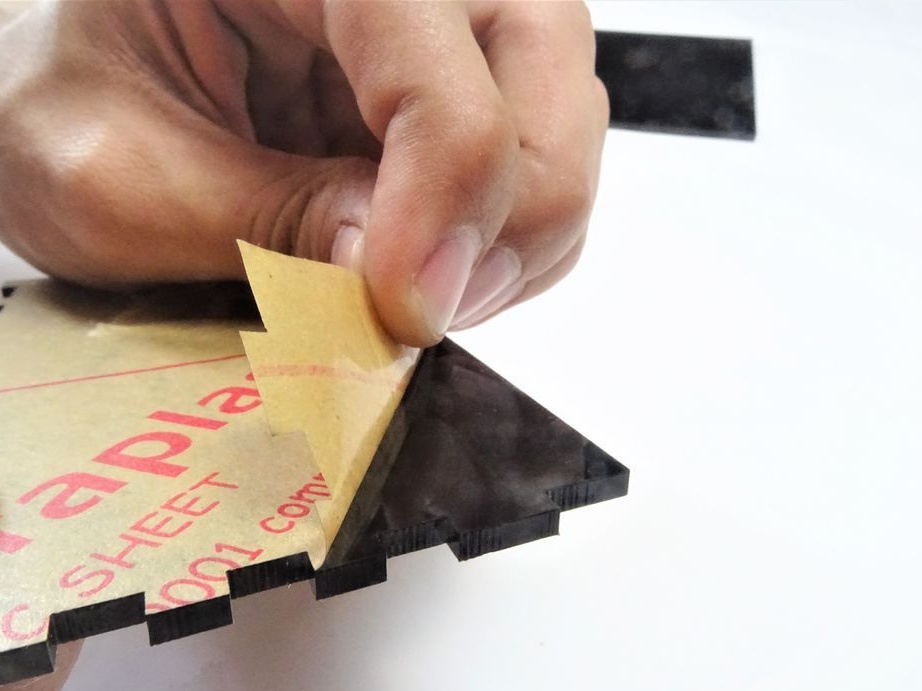
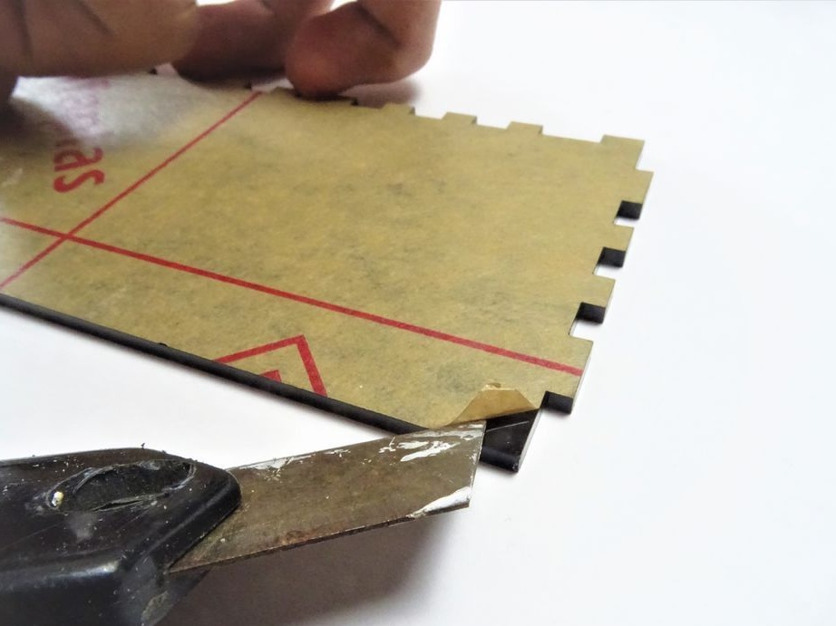
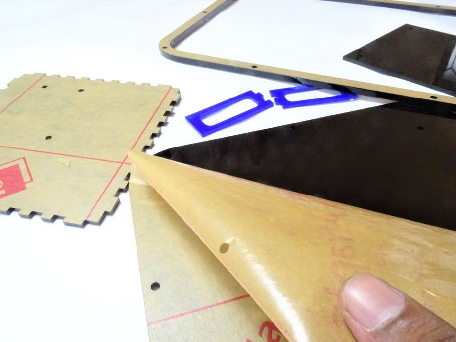
After manufacturing the parts, removes the protective layer from them.
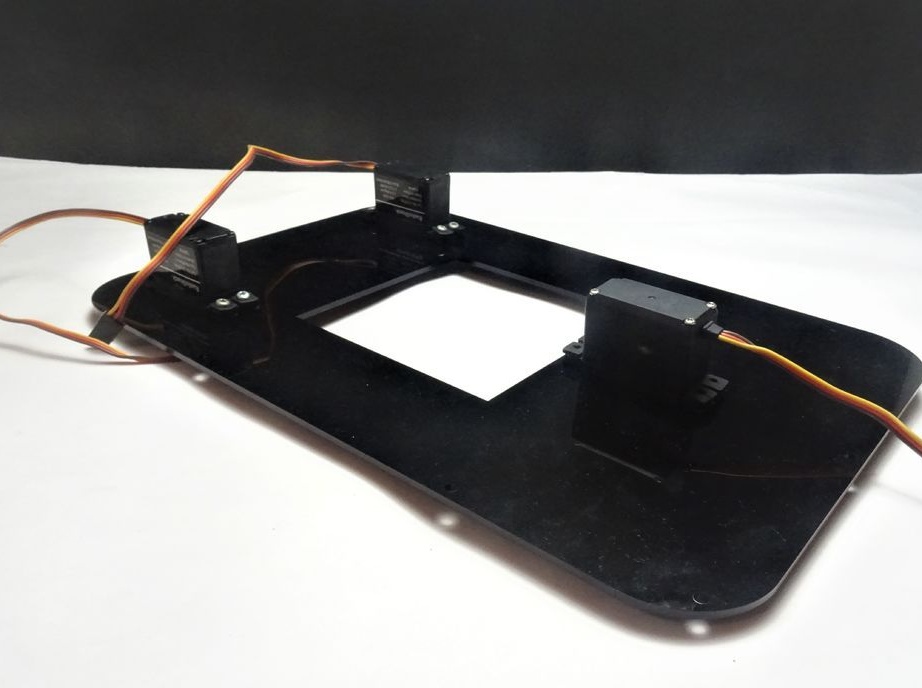
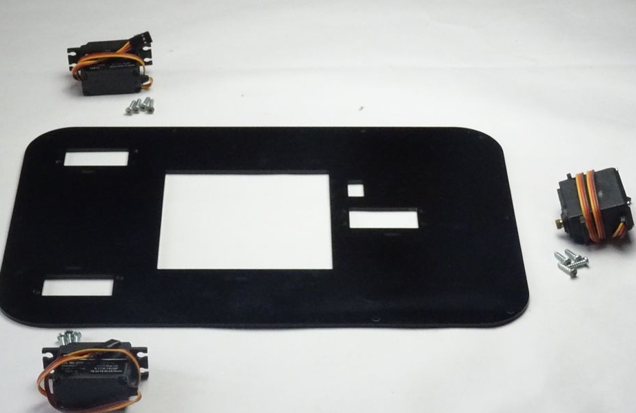
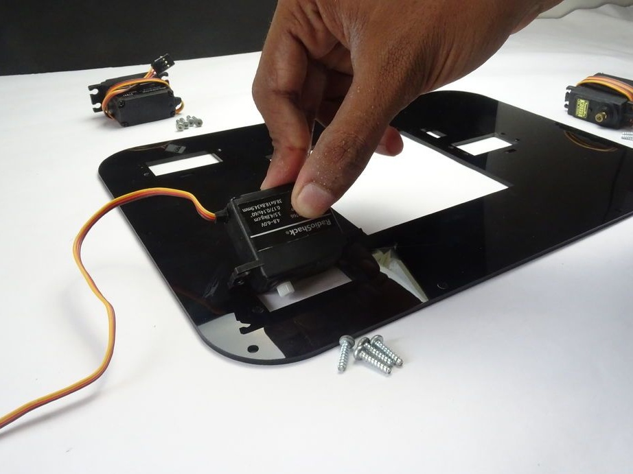
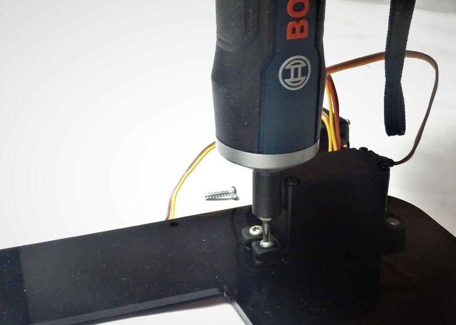
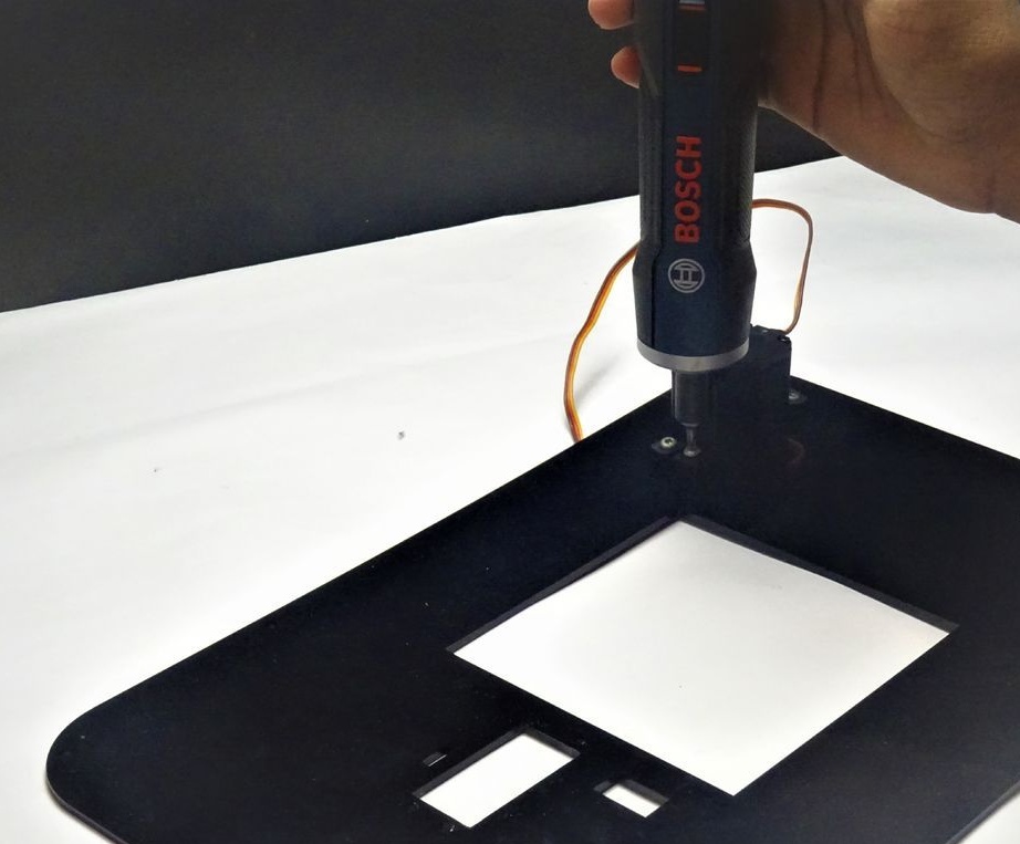
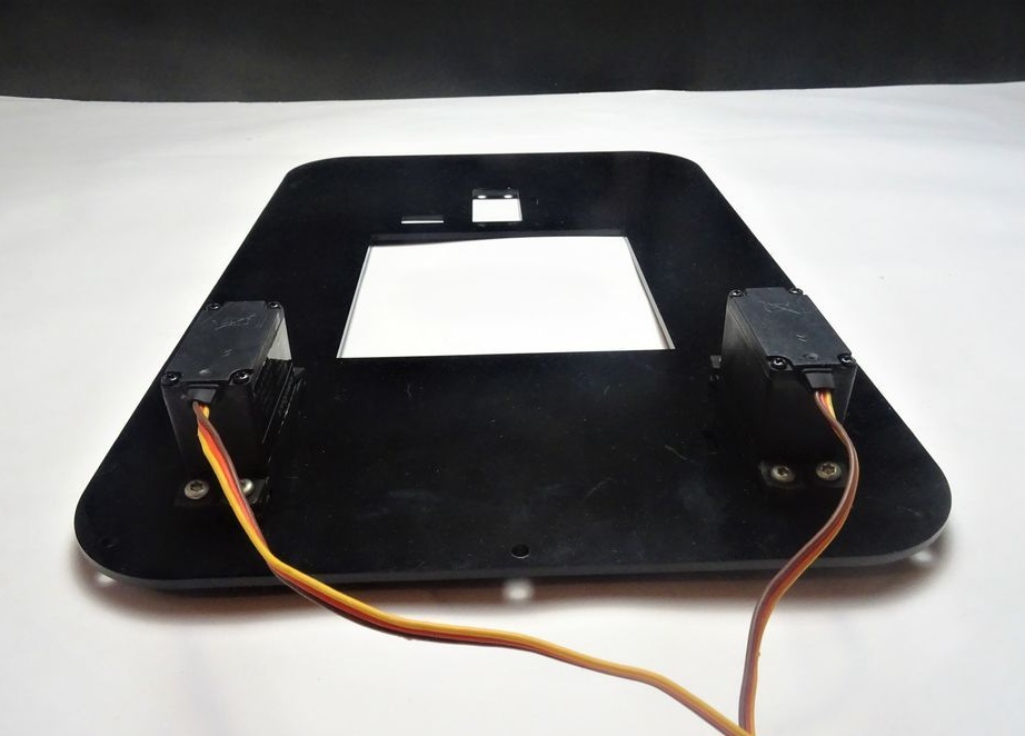
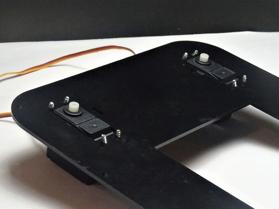
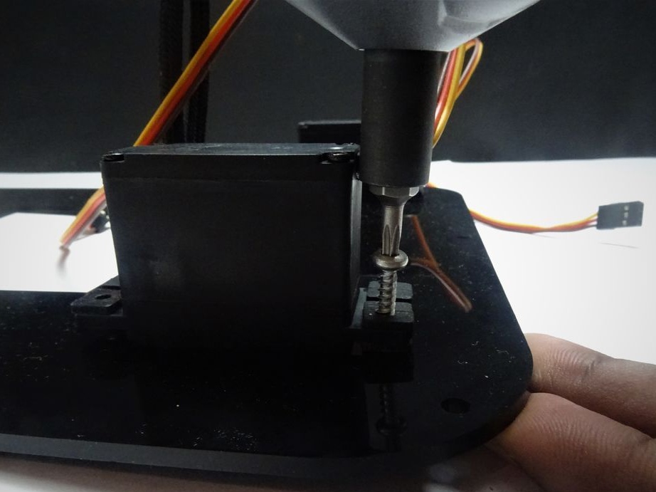
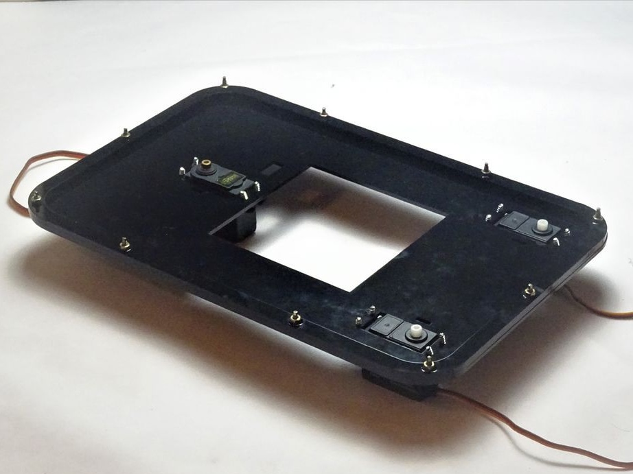
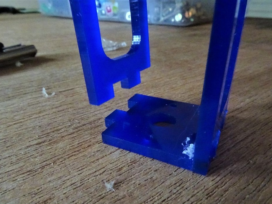
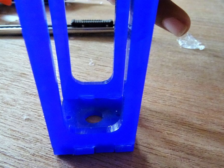
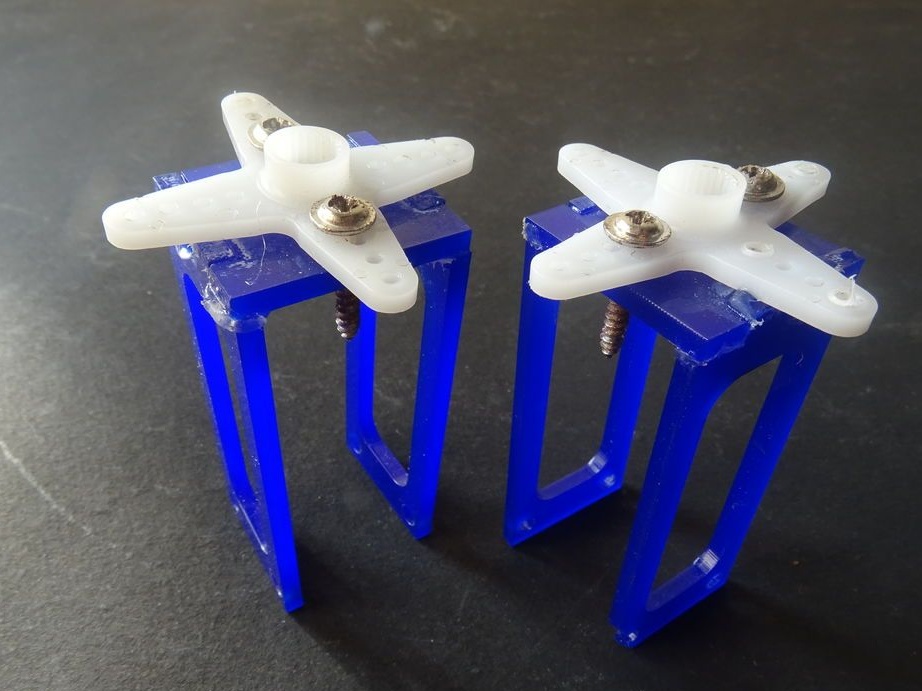
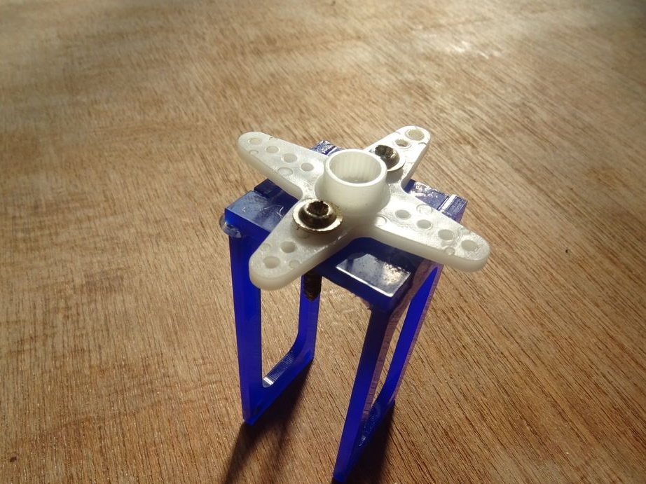
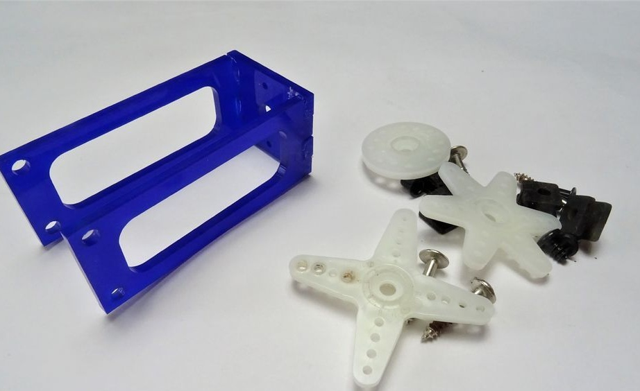
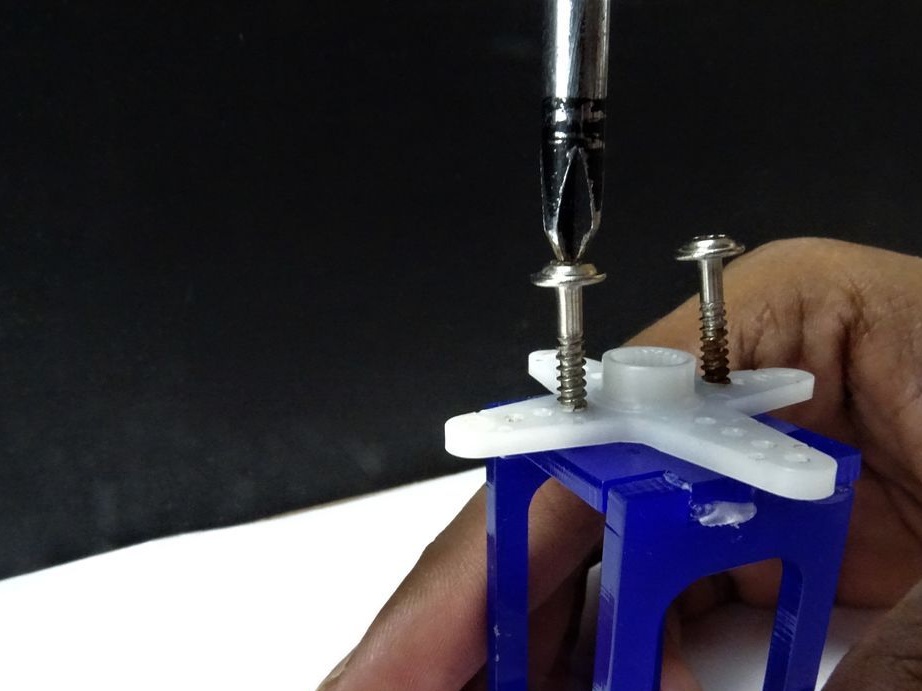
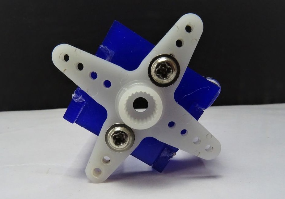
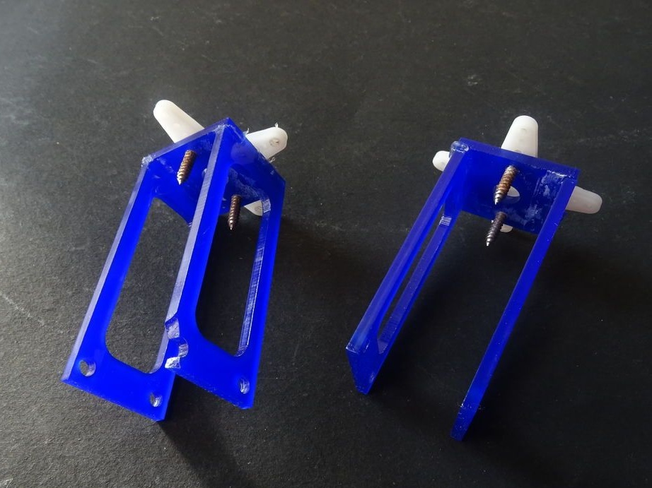
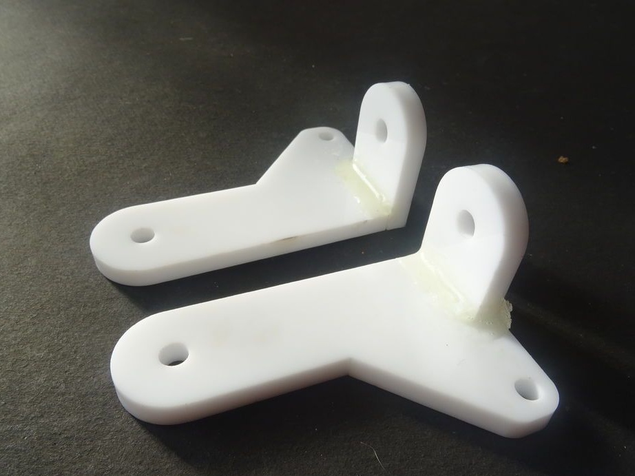
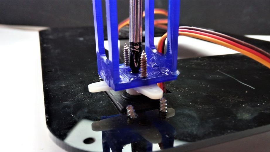
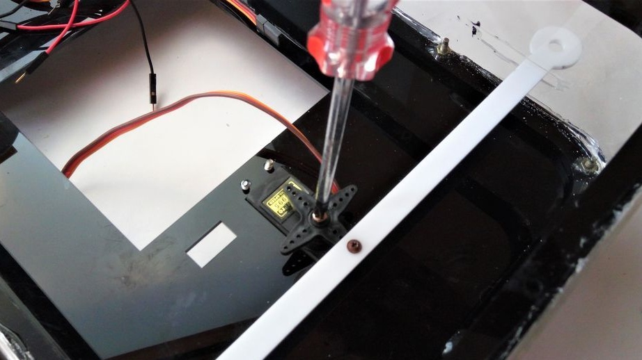
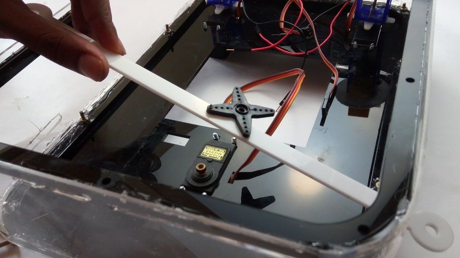
Step Three: Install Servo Motors
All three servomotors are screwed to the platform. Two to the back and one to the front.
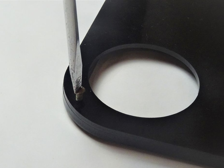
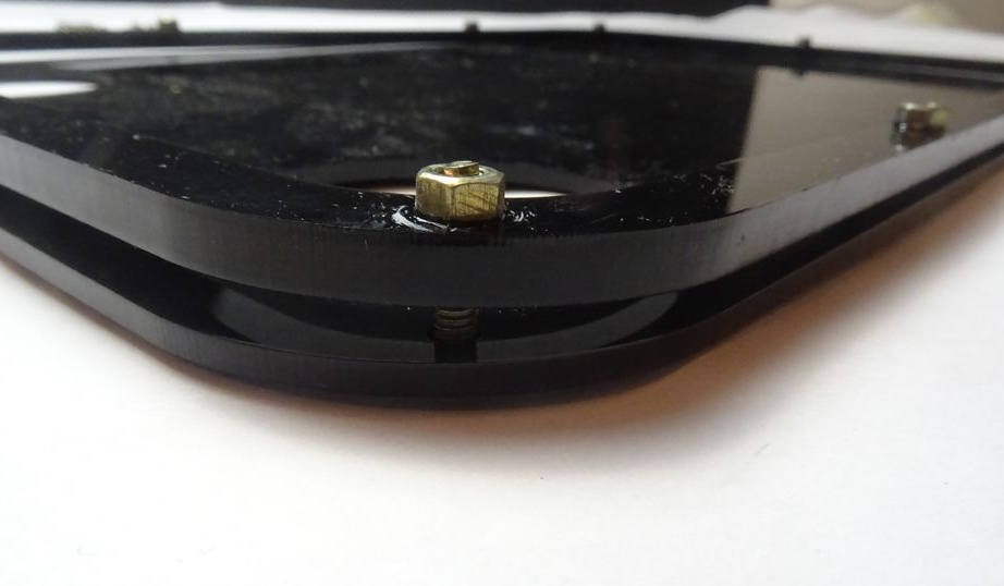
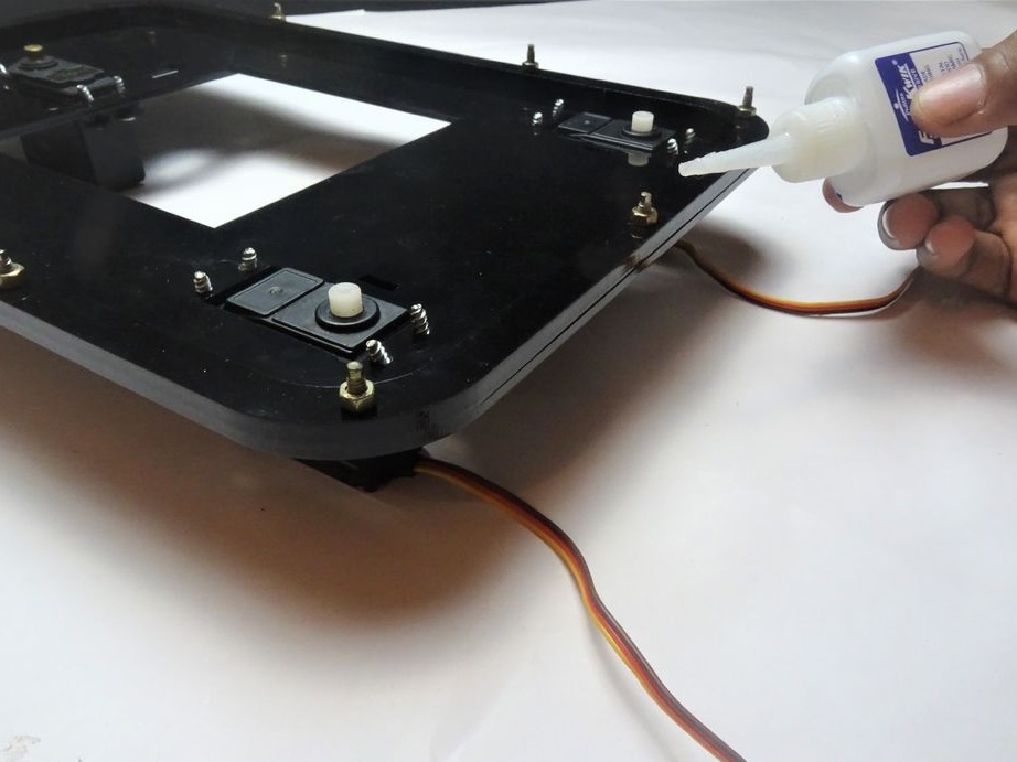
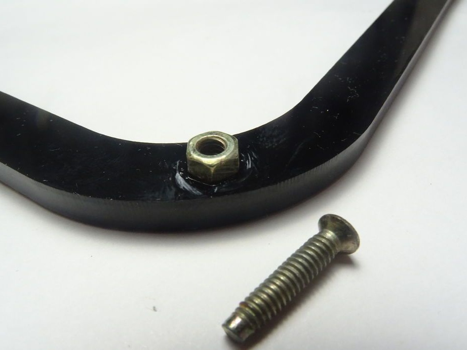
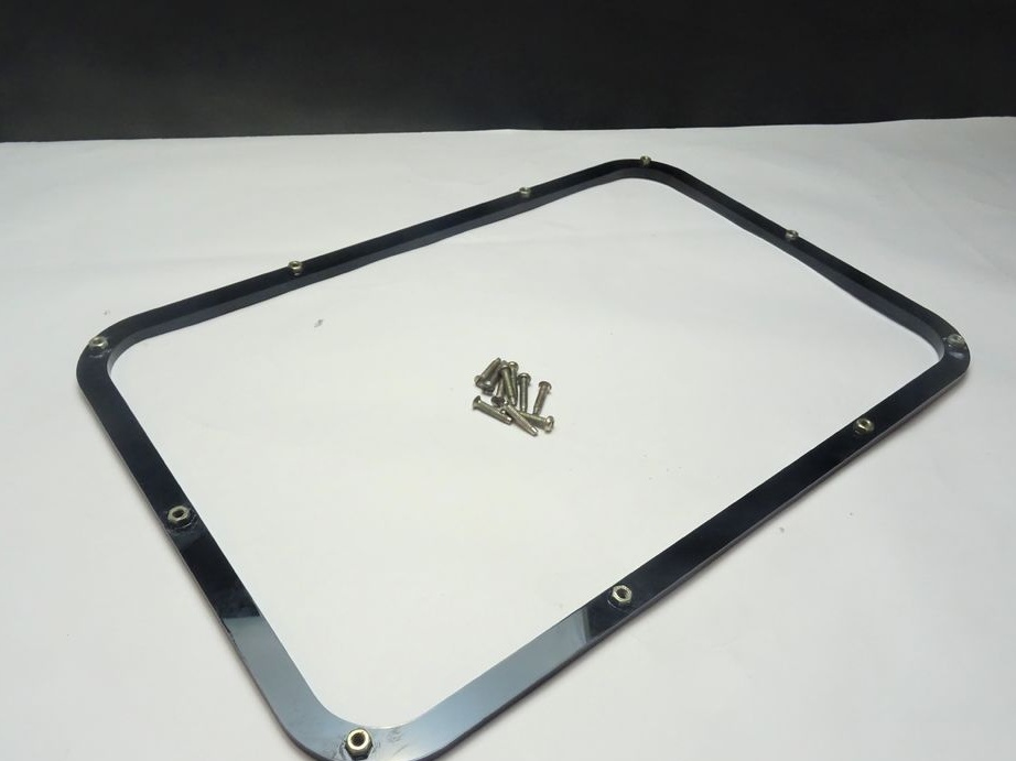
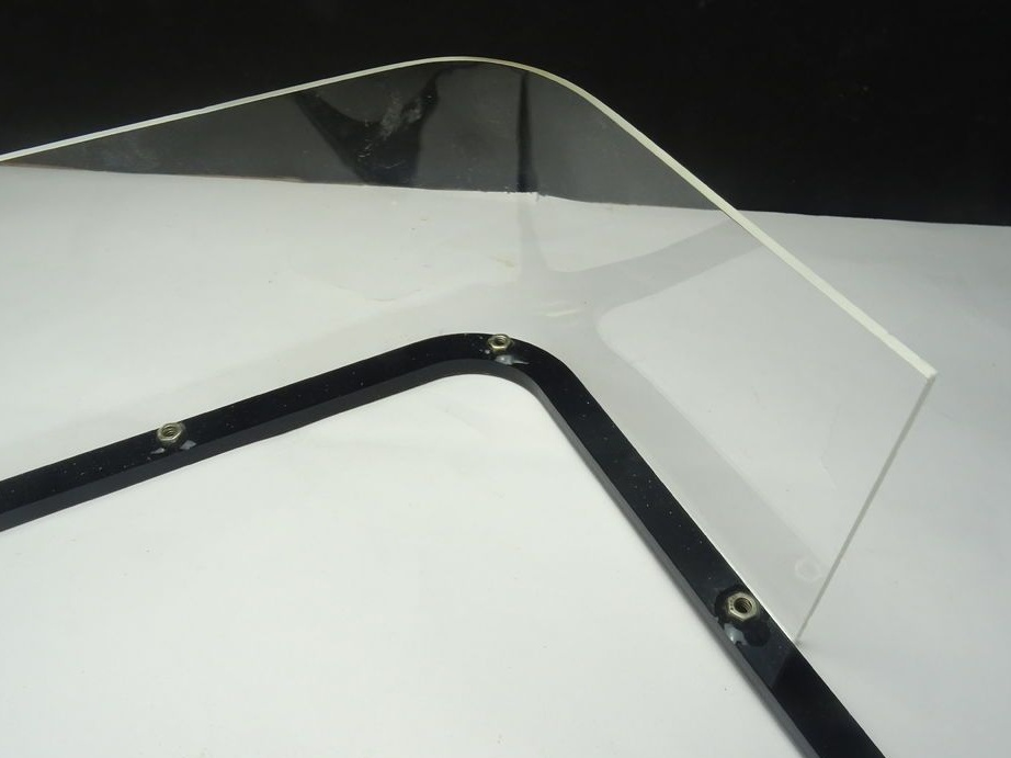
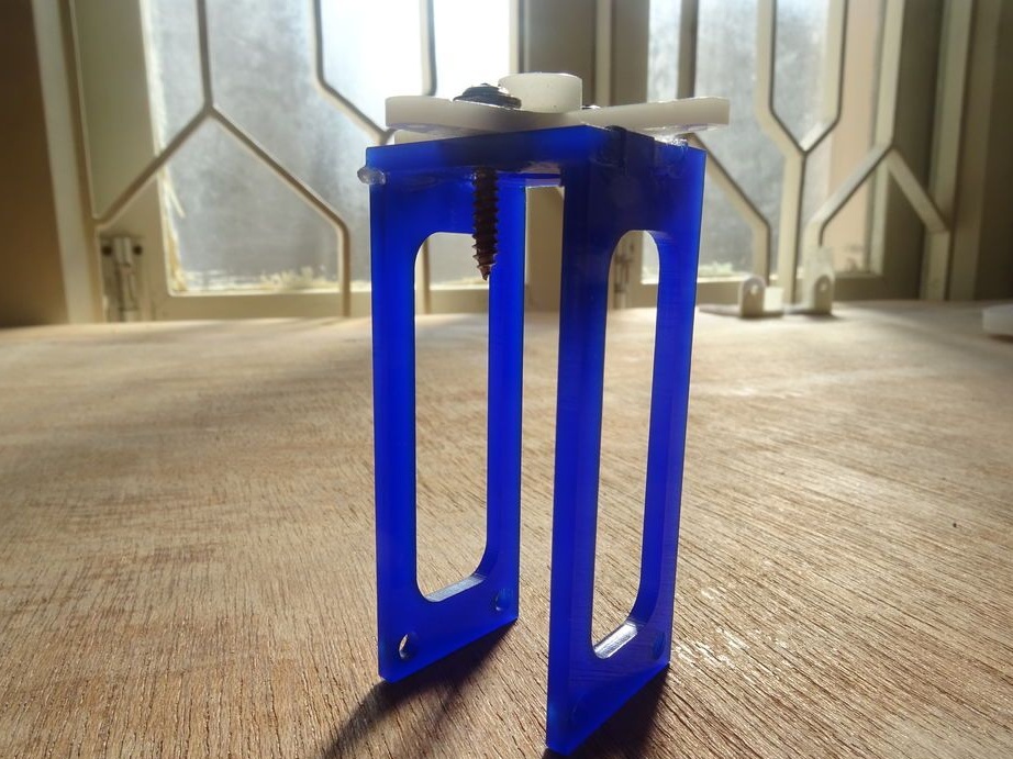
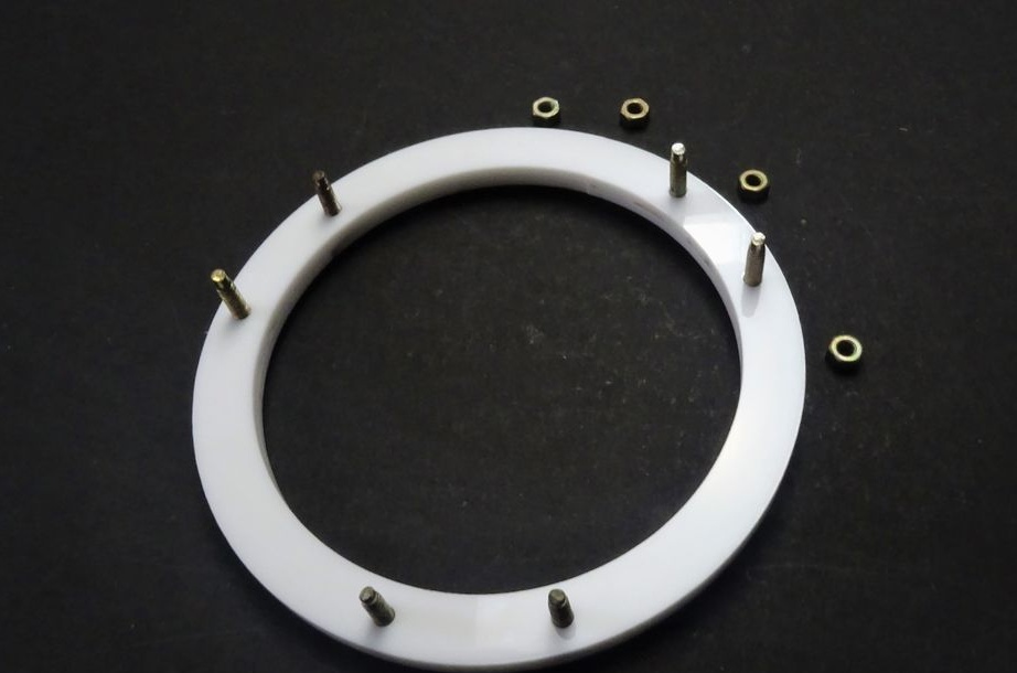
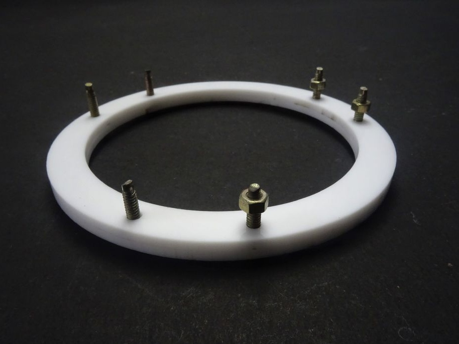
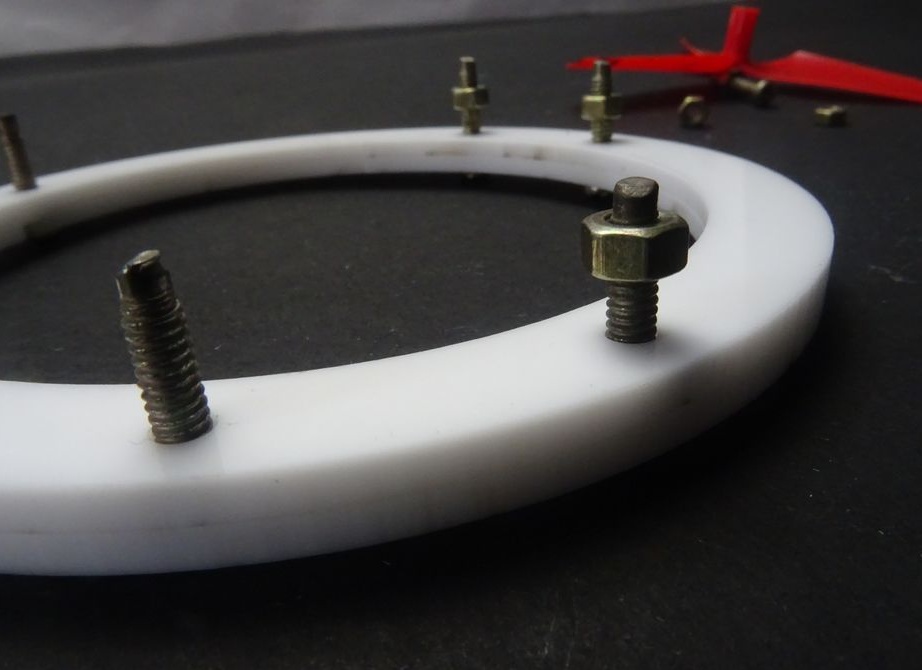
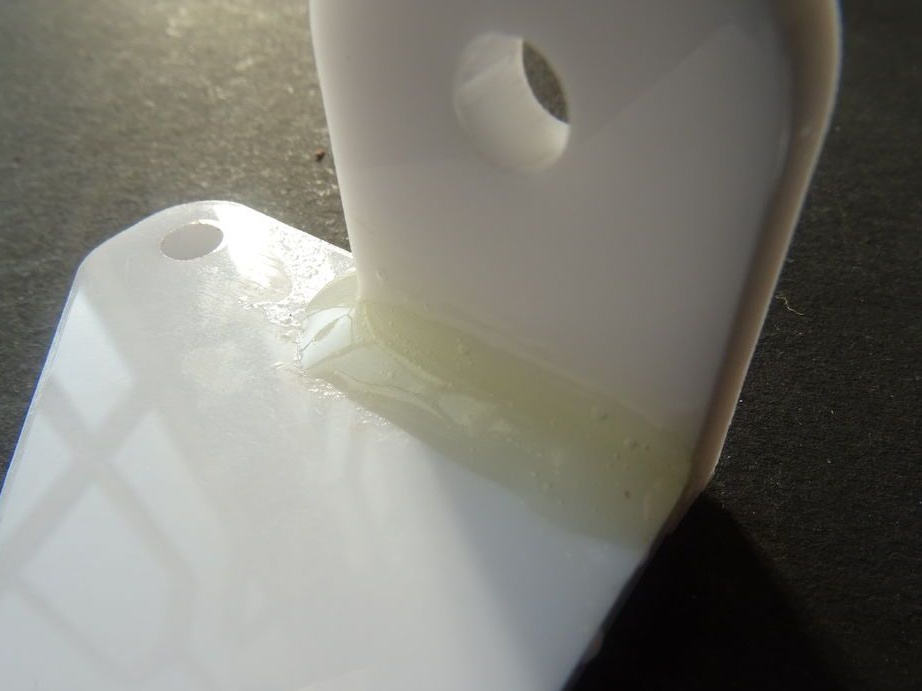
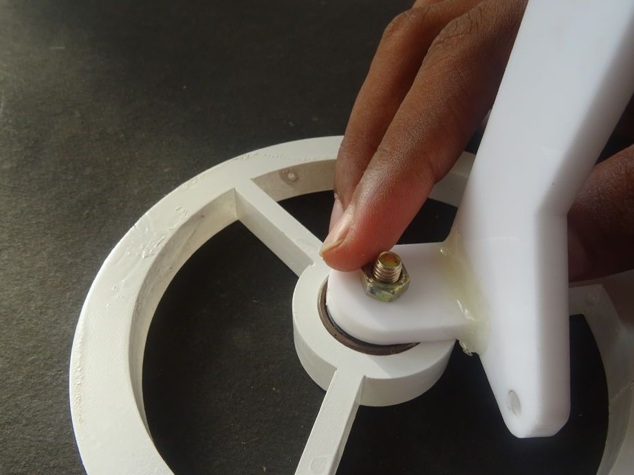
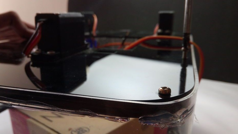
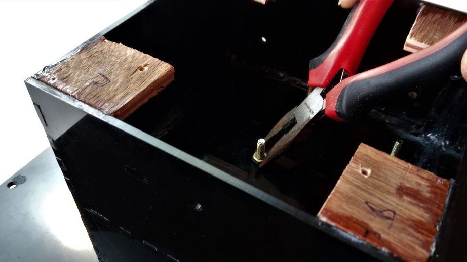
Step Four: Nuts
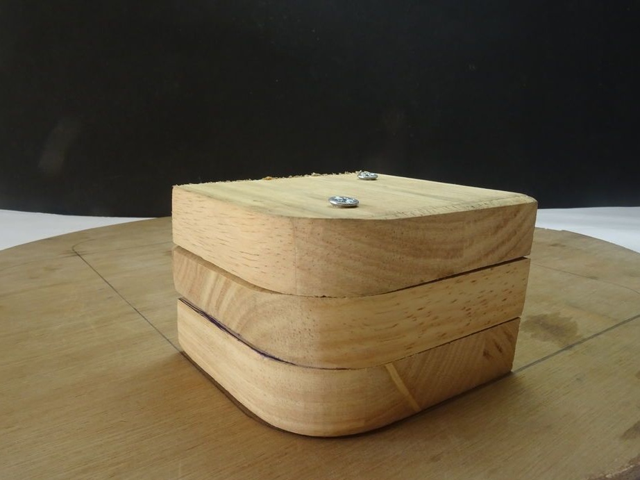
For access to the mechanisms, the upper and lower parts are bolted together. Glues the nuts on the superglue to the frame, and then reinforces it with epoxy.
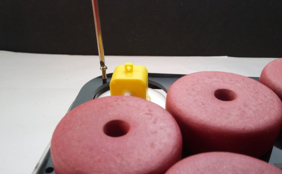
Step Five: Floats
Glue floats.
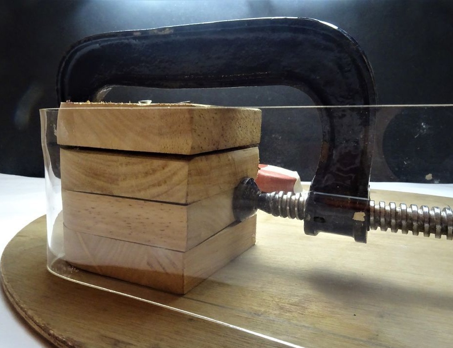
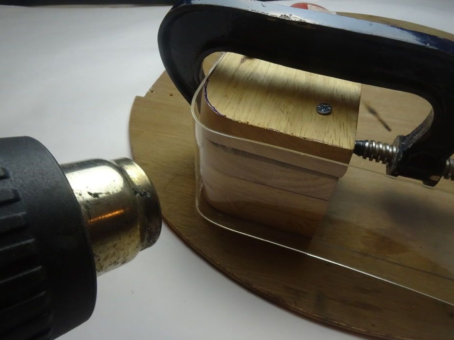
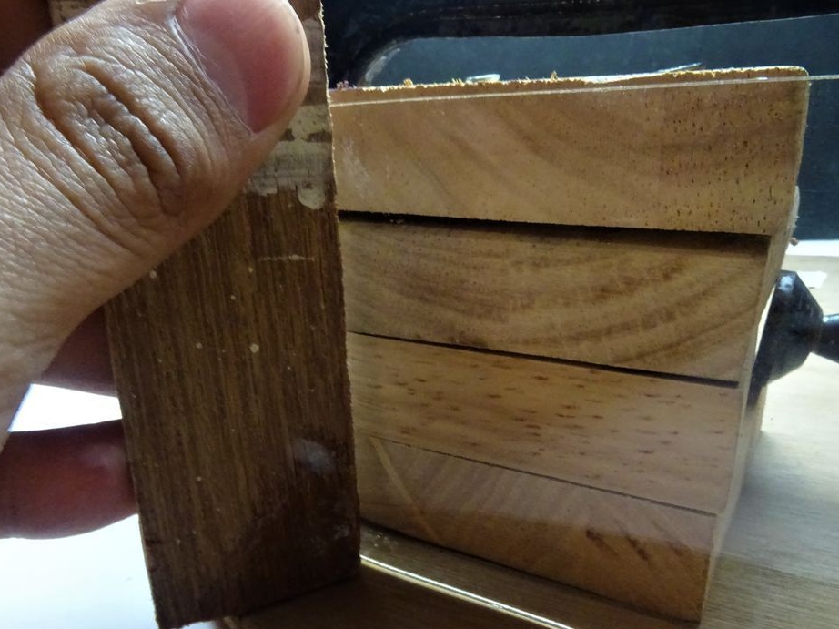
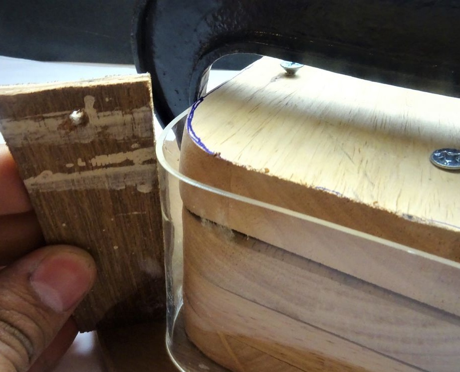
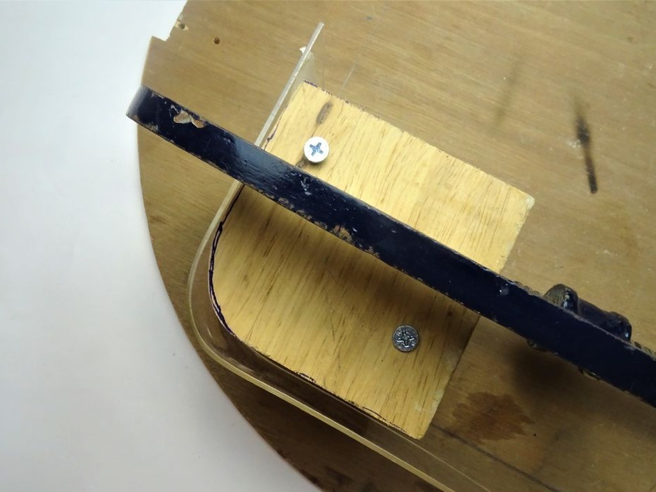
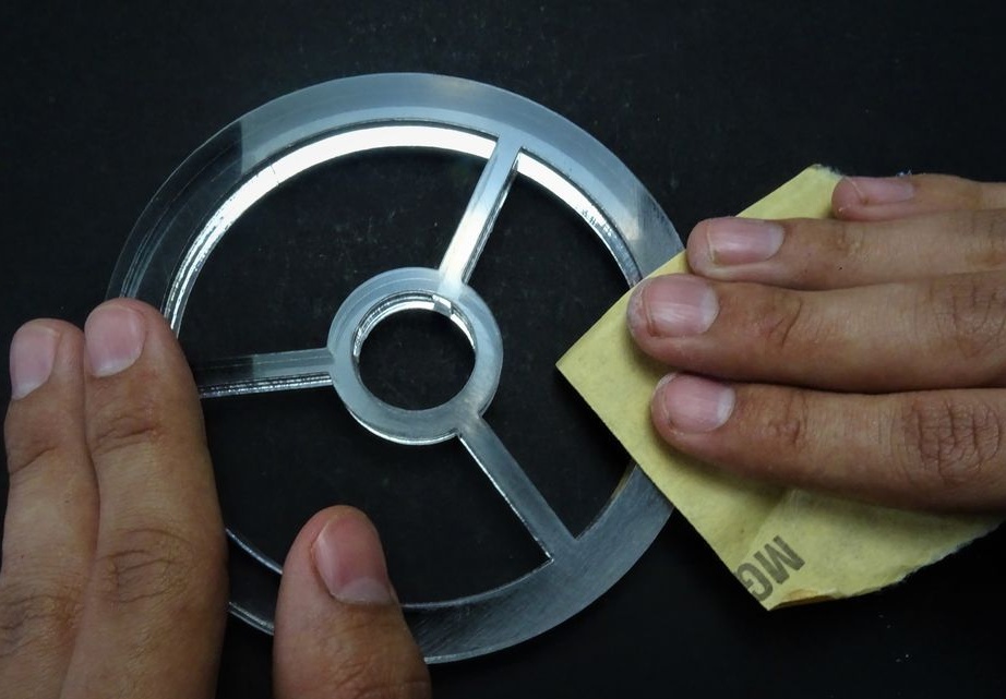
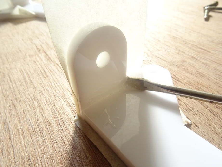
Step Six: Shaping Acrylic
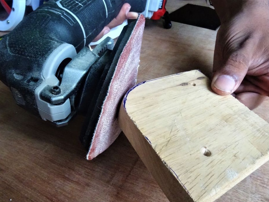
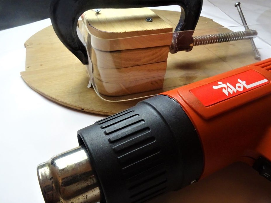
To bend acrylic, a craftsman makes a template from wood.
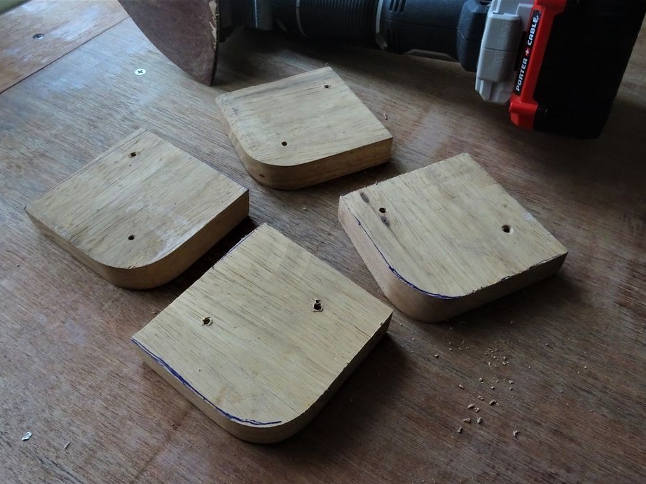
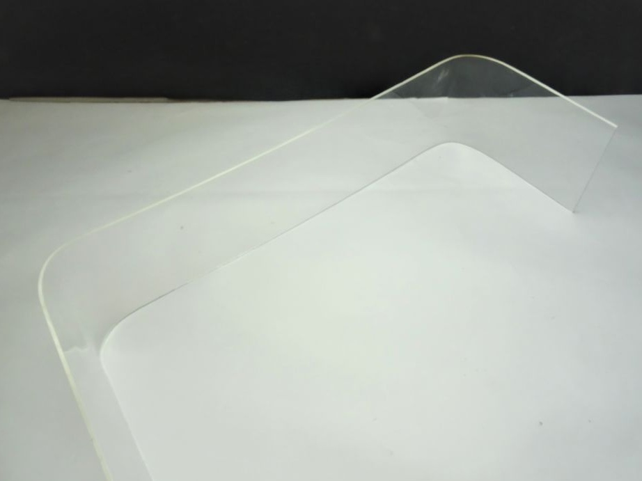
He clamps the part with a clamp and, heating it with a hairdryer, gives the part the desired shape.
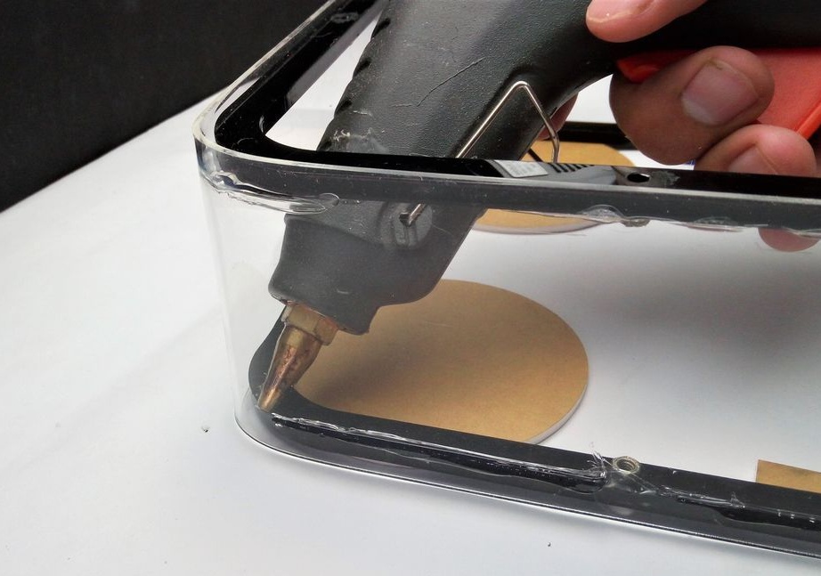
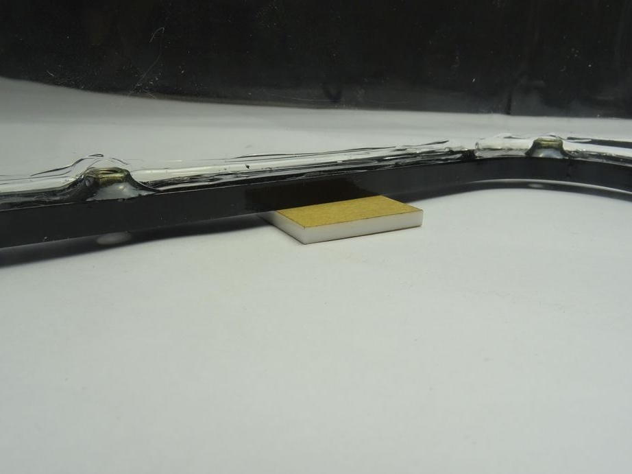
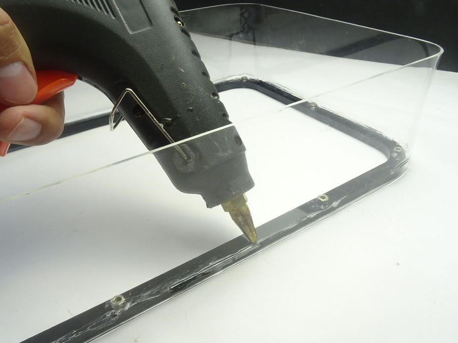
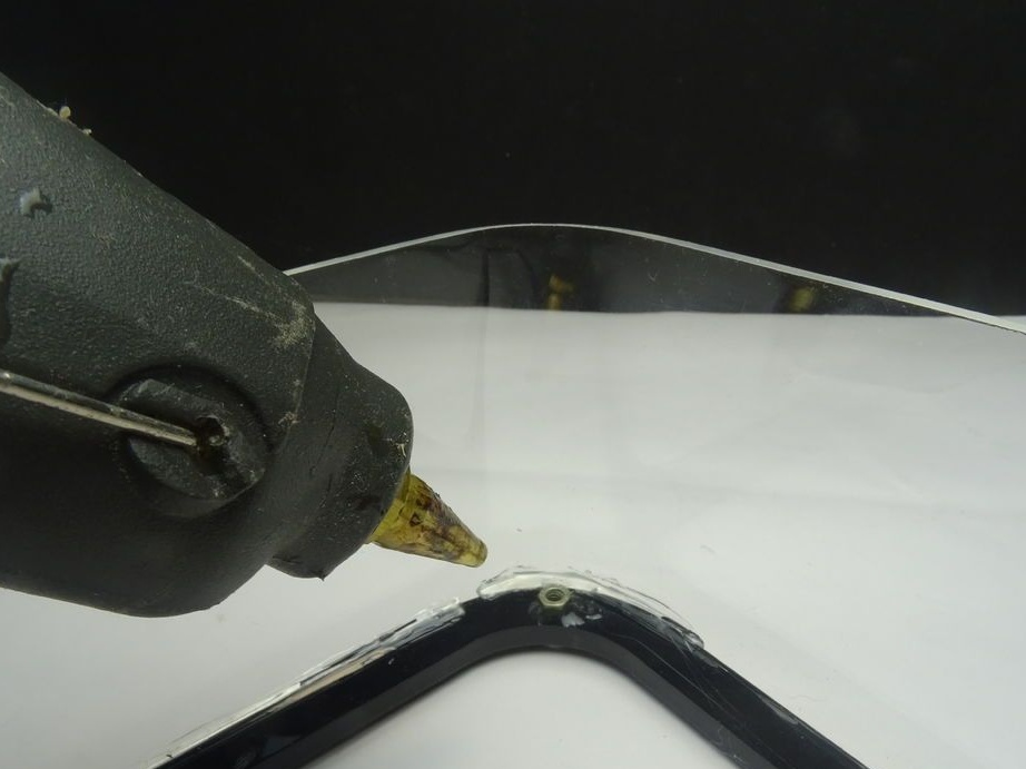
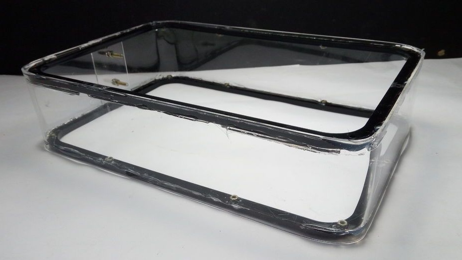
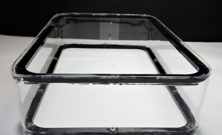
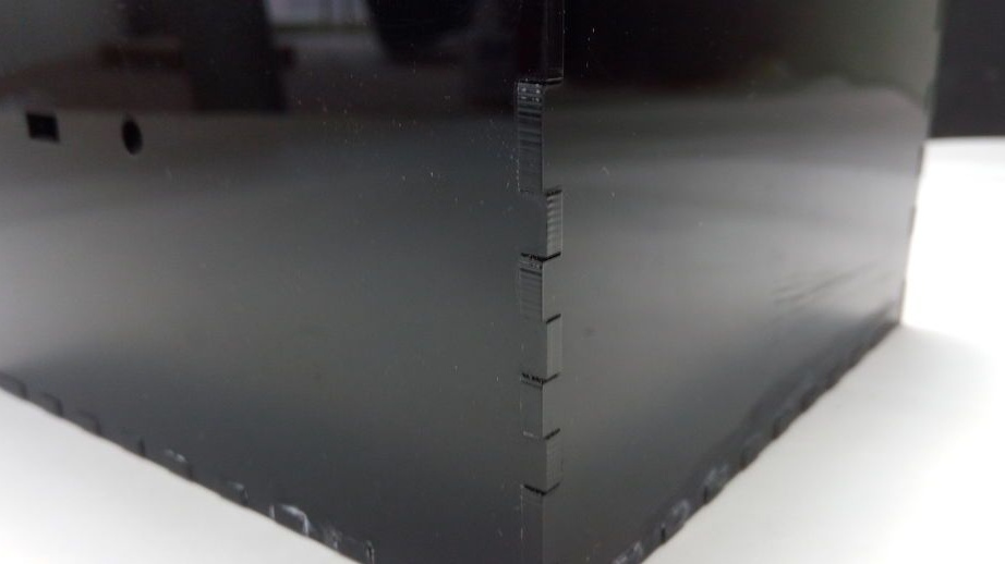
Seventh step: framework
Glues the upper and lower frames to the transparent body. The seams are carefully sealed with hot glue.
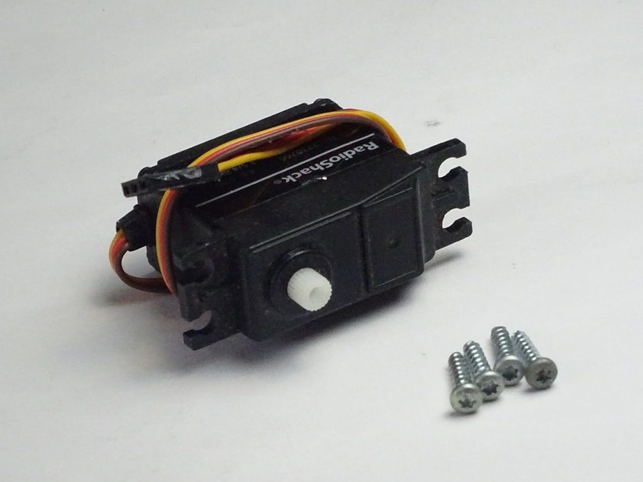
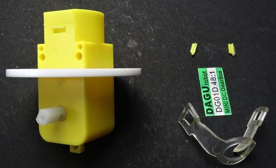
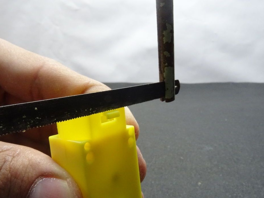
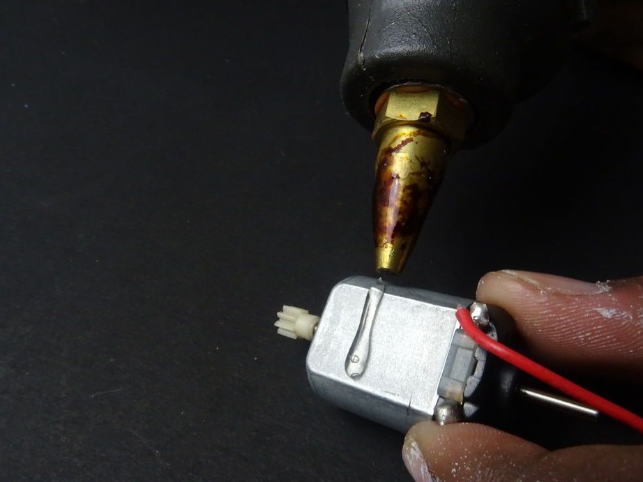
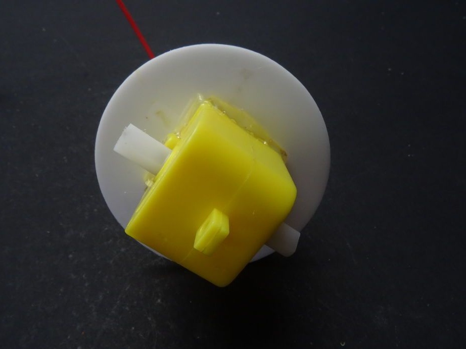
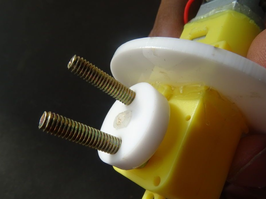
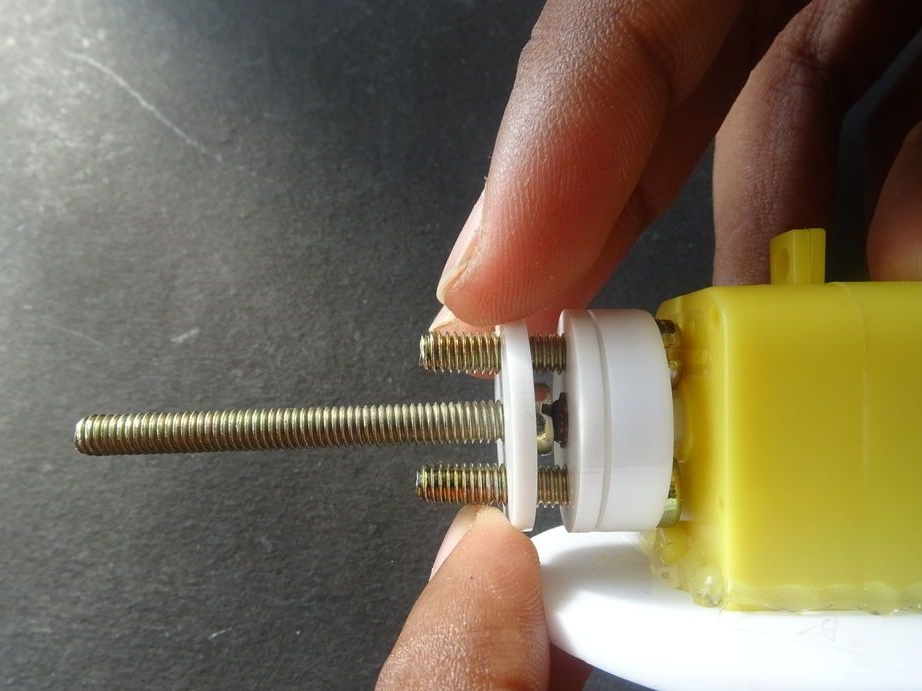
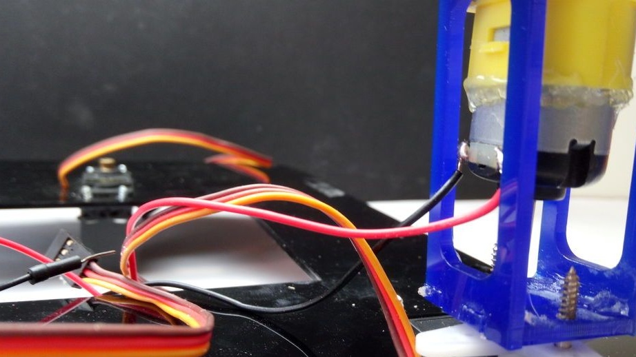
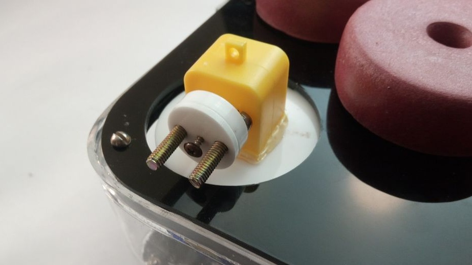
Step Eight: Engine Tuning
Now you need to process the engine casing to install parts on it.
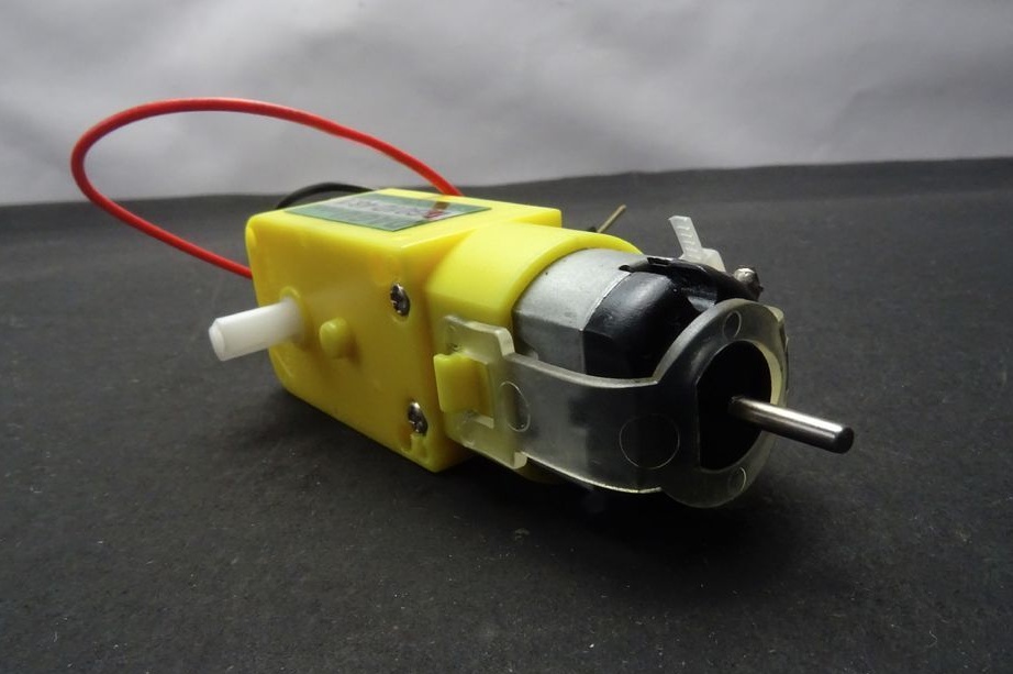
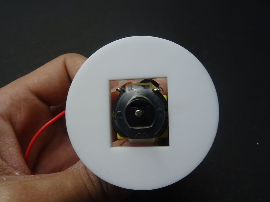
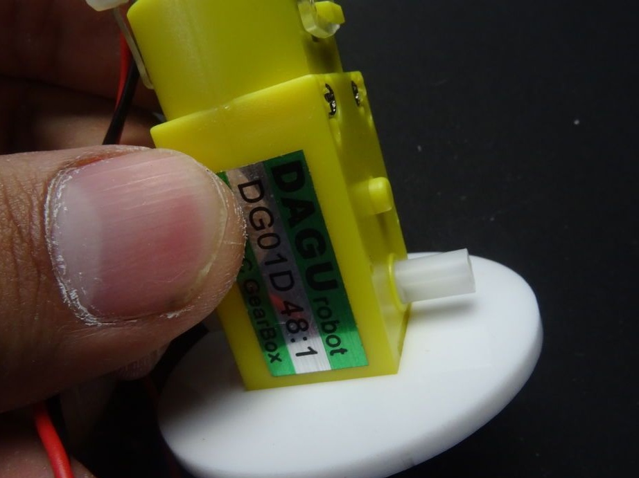
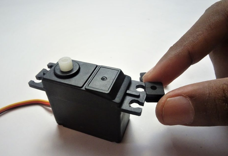
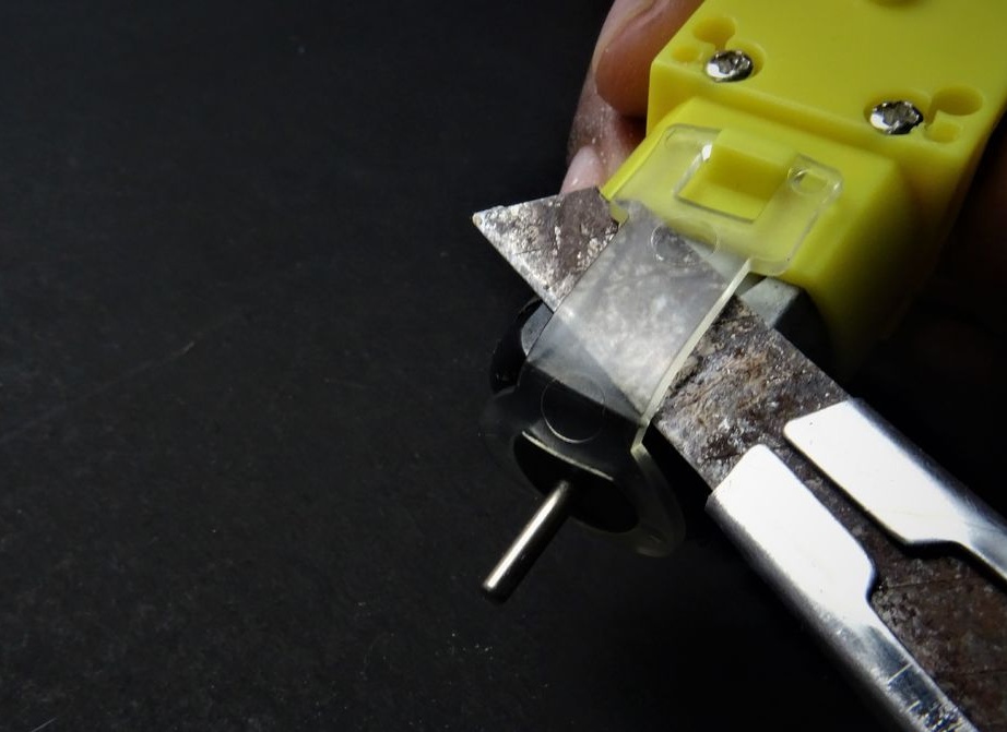
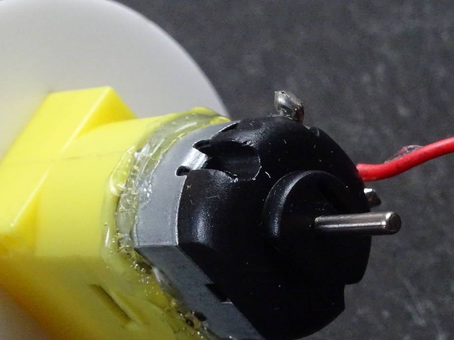
Cuts off all protruding parts from the body, up to the sticker.
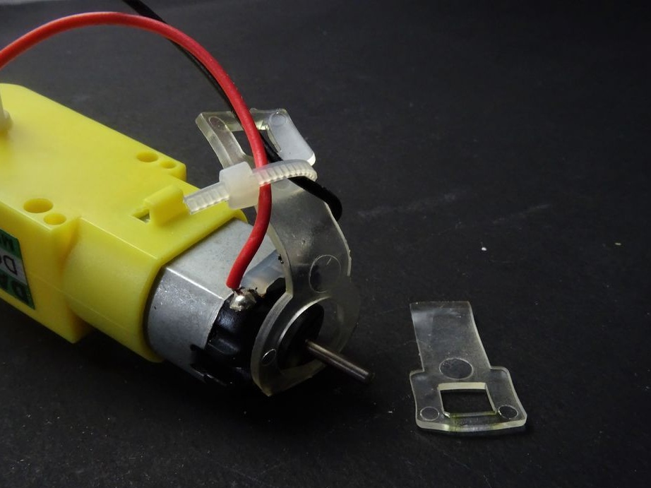
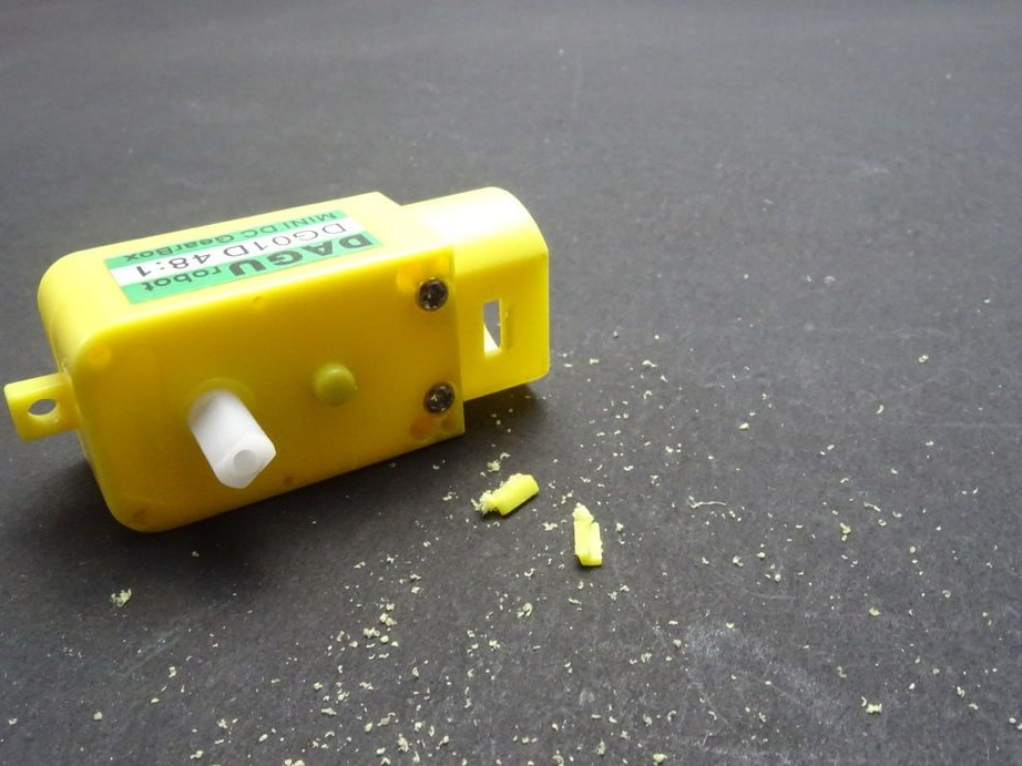
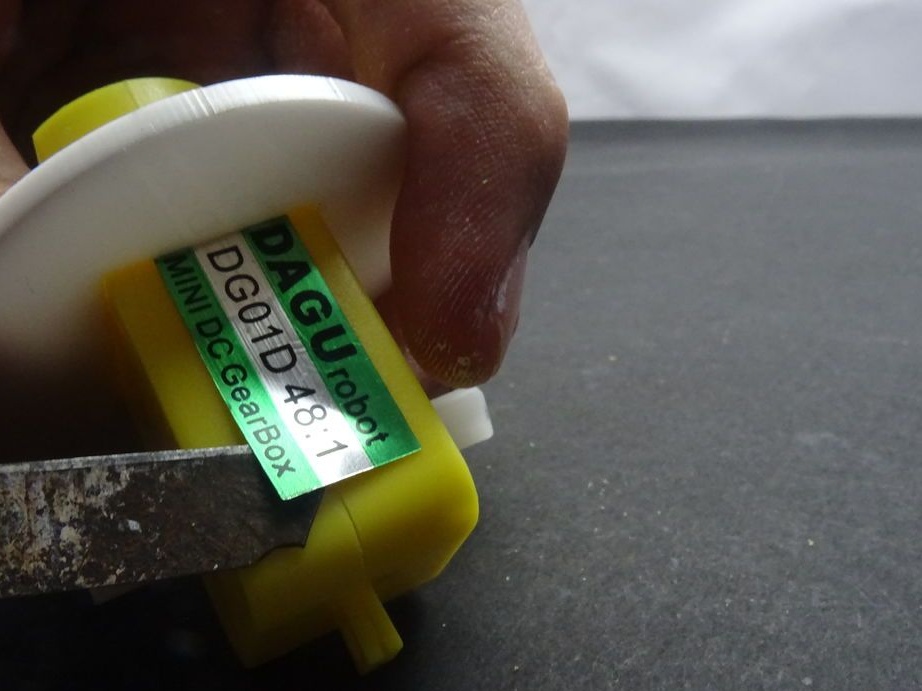
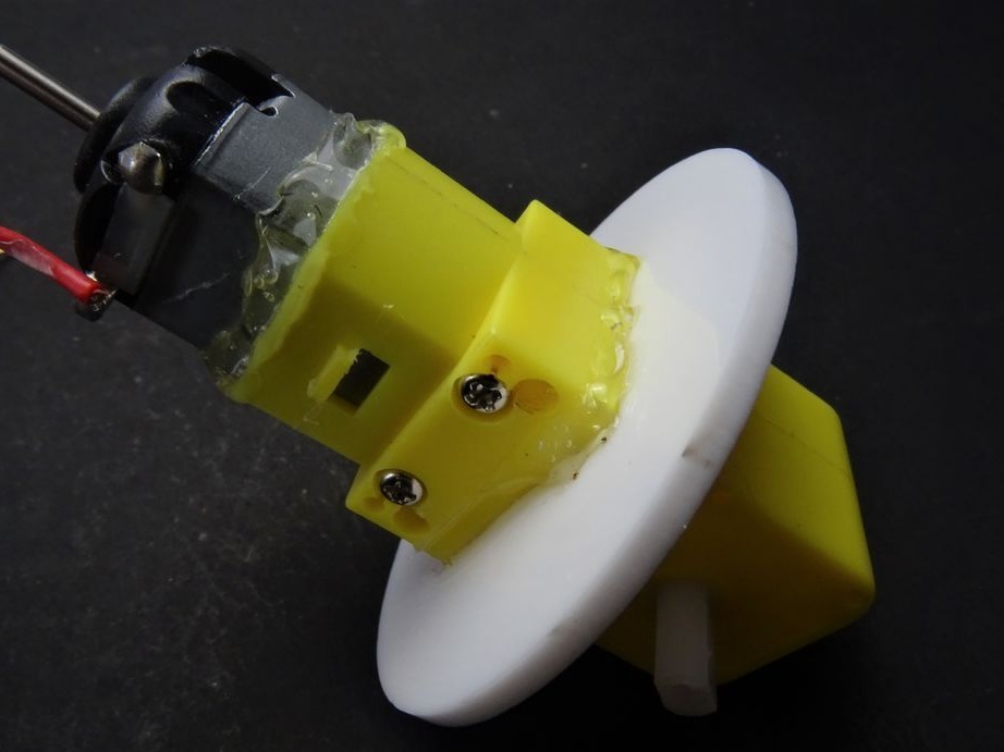
Installs the part on the body and glues it. Since it was necessary to cut off the engine mount (latches), the engine also fixes with glue.
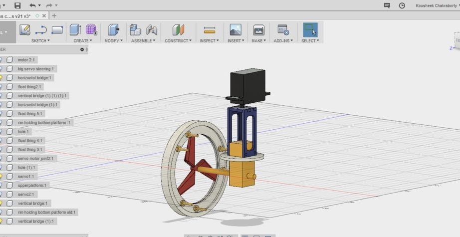
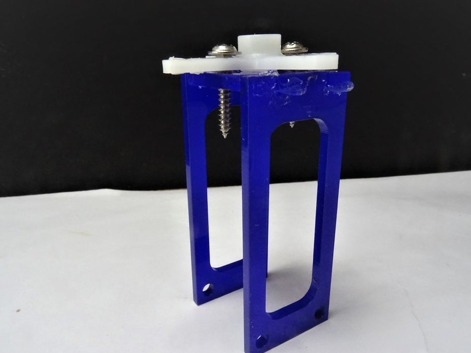
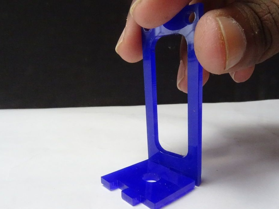
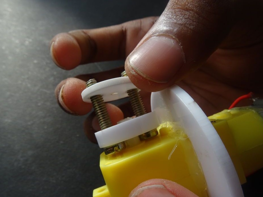
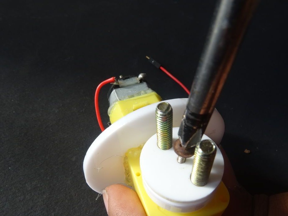
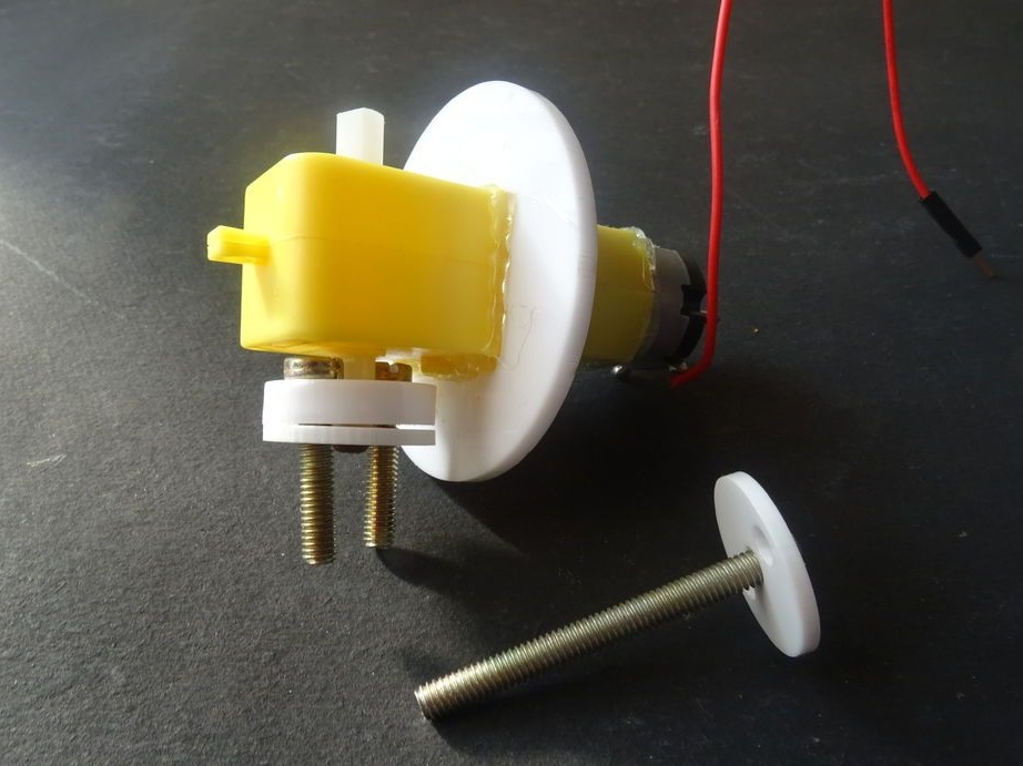
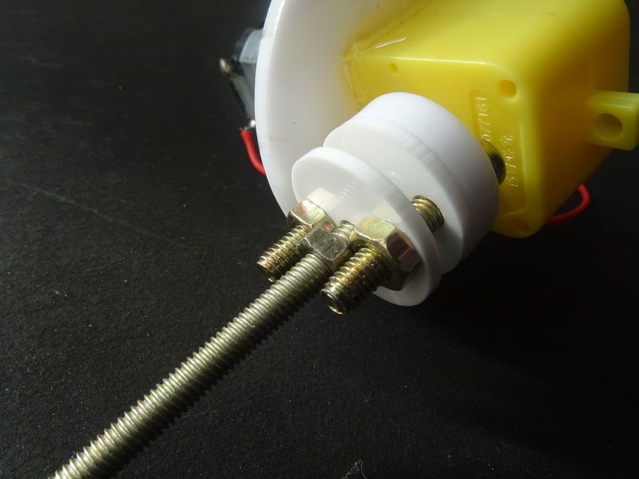
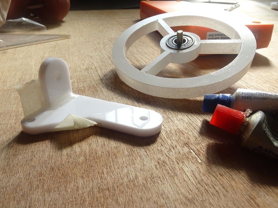
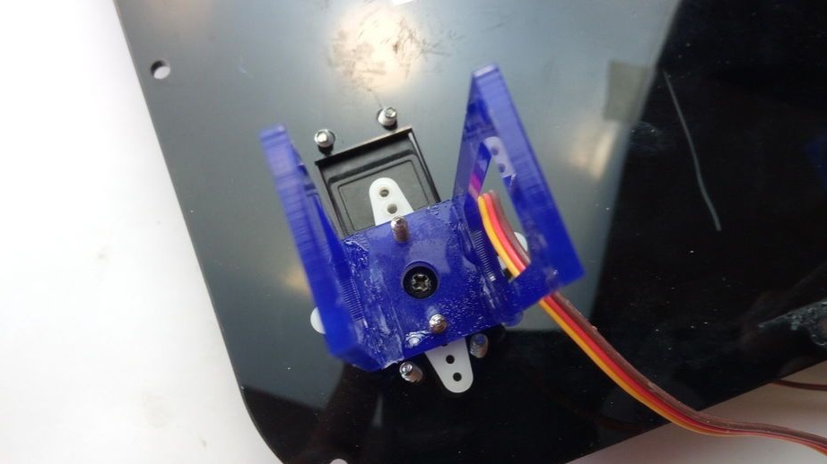
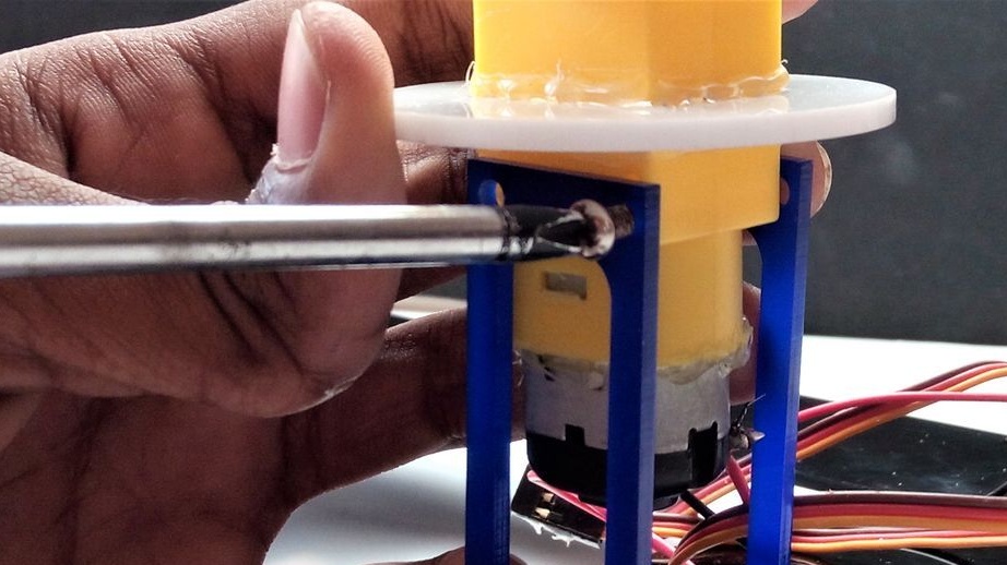
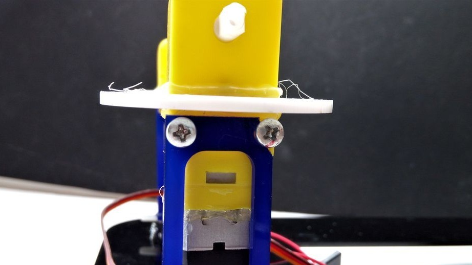
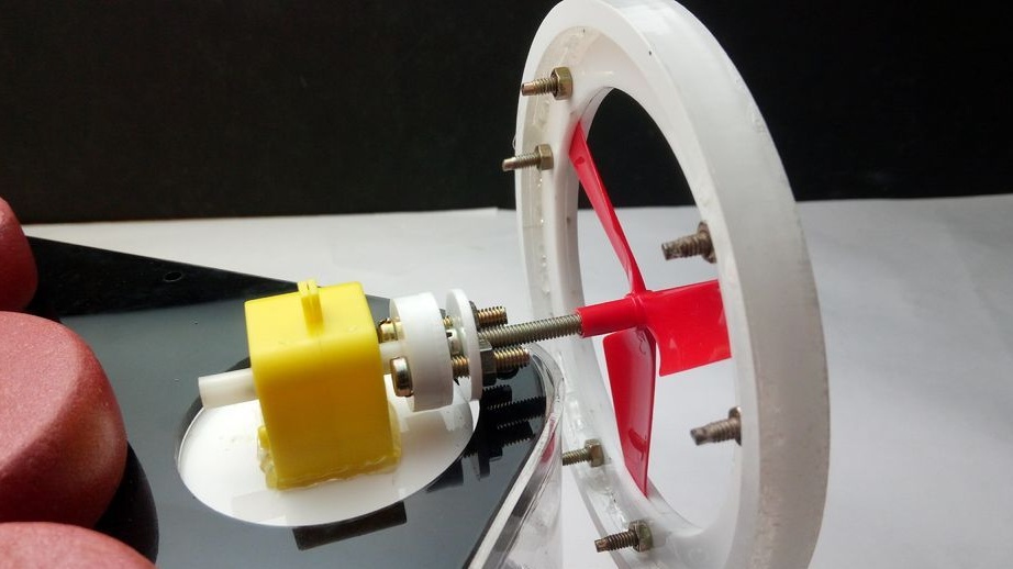
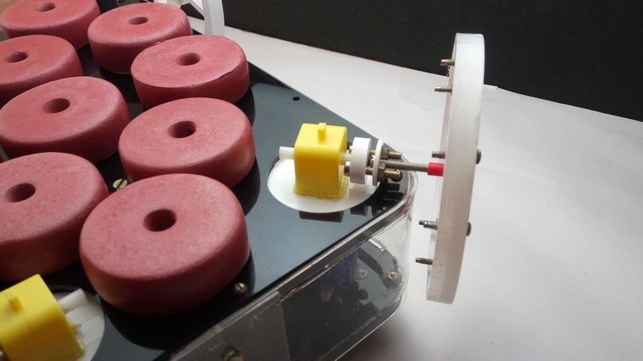
Step Nine: Swivel Mechanism
Assembles a rotary housing. An engine will be installed in it, and it will connect to the servo drive.
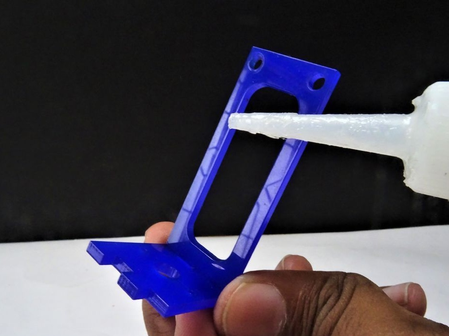
Glues the case.
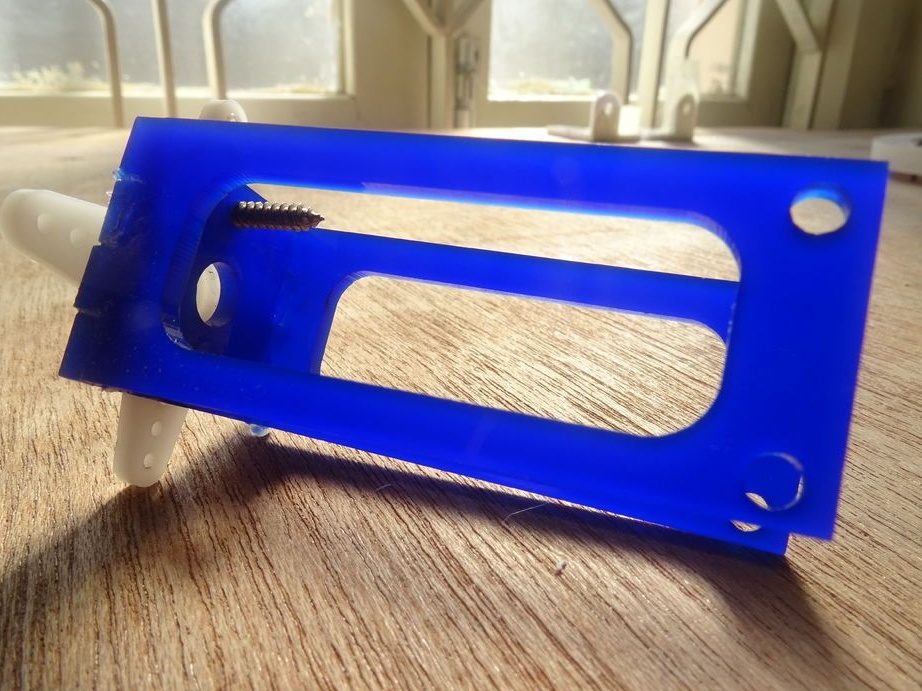
Screws on the coupler.
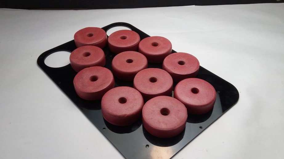
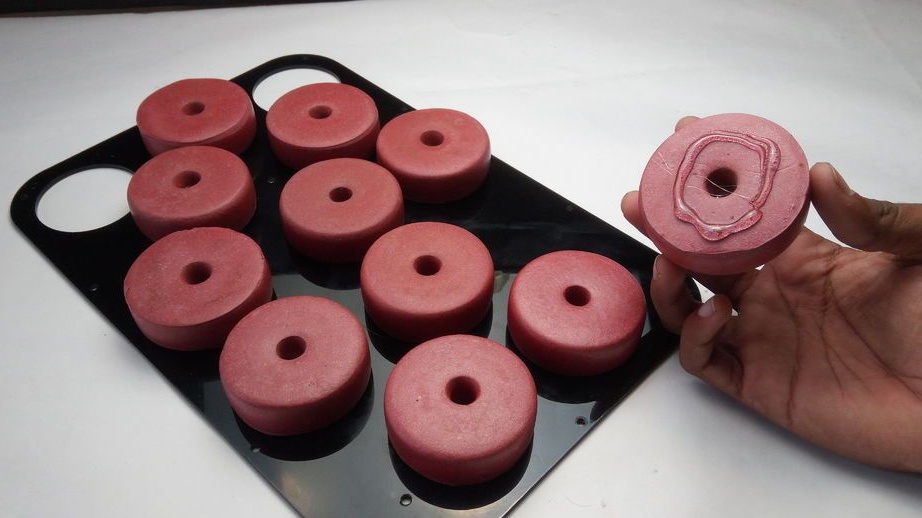
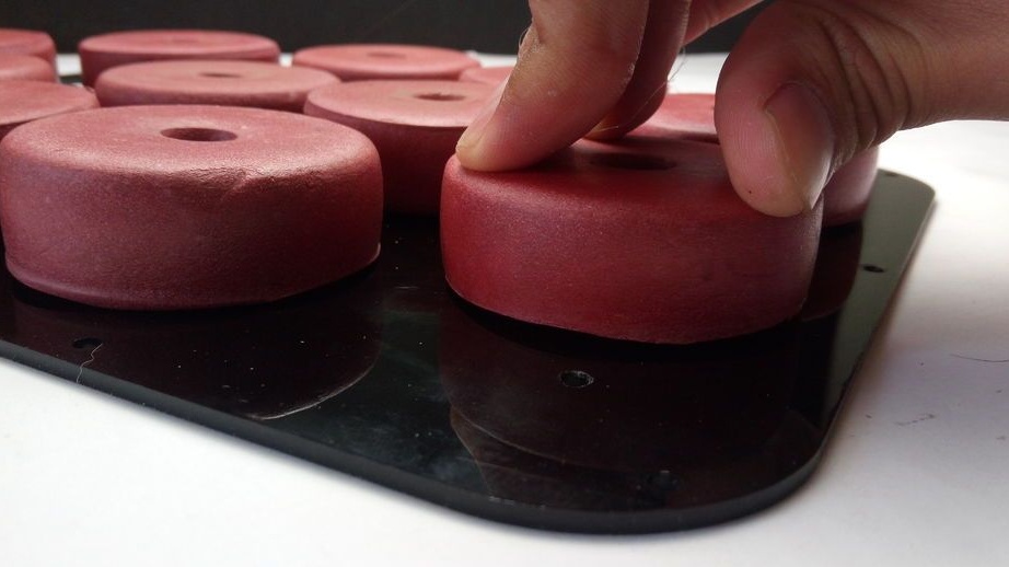
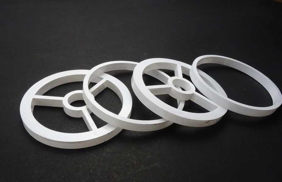
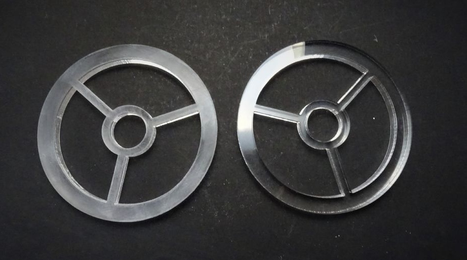
Step Ten: Painting
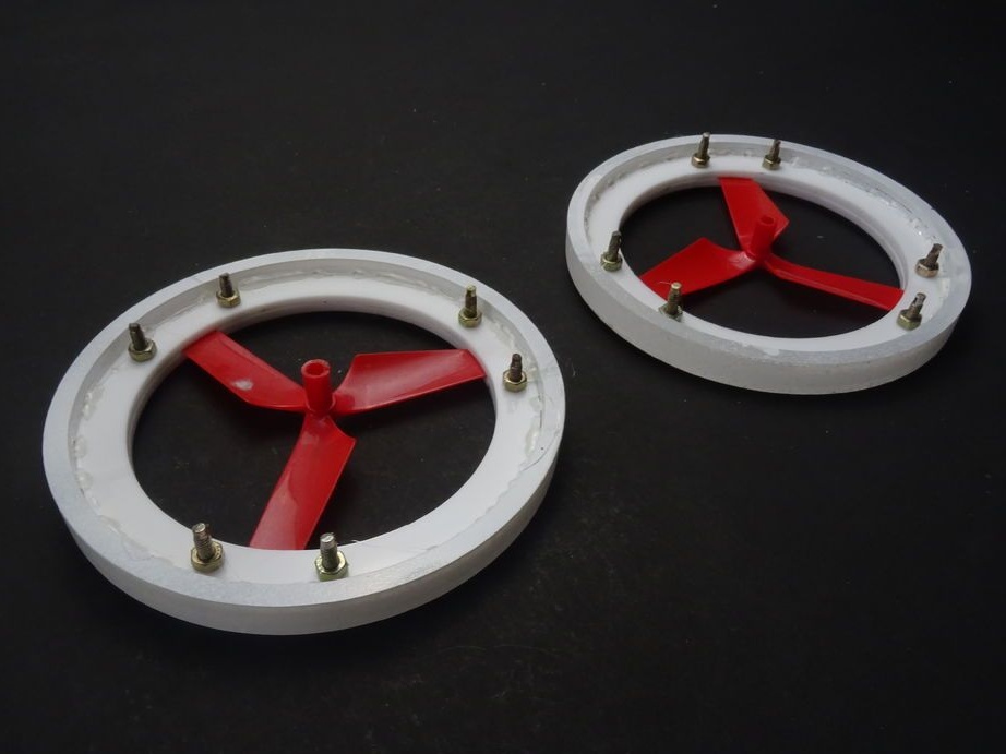
Since the master did not have white acrylic of the required thickness, the wheels and rim were cut out of transparent acrylic and then painted white.
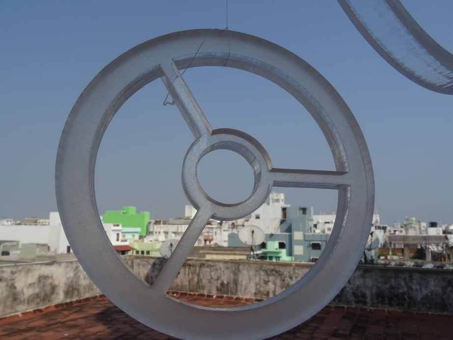
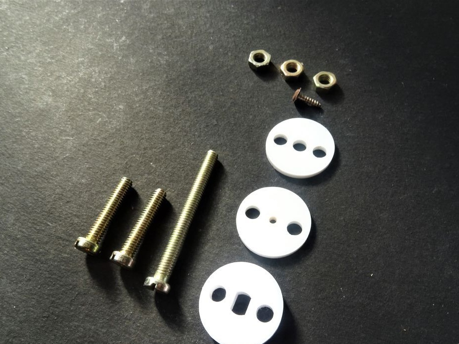
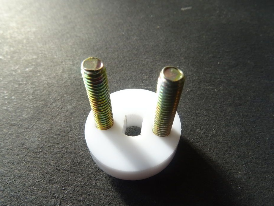
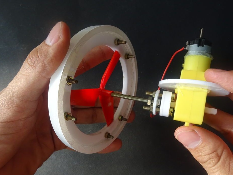
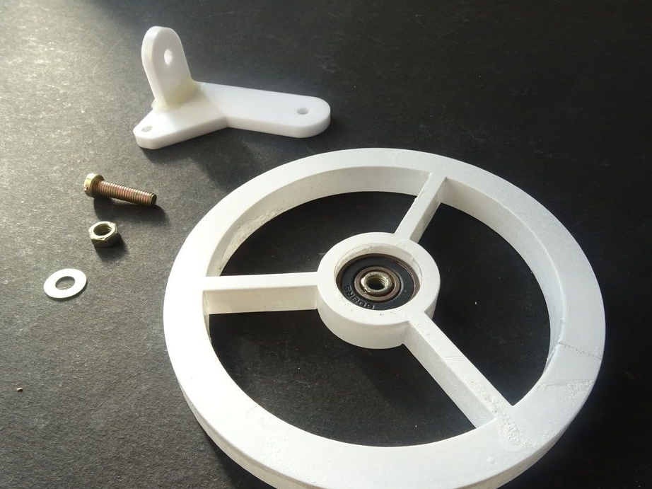
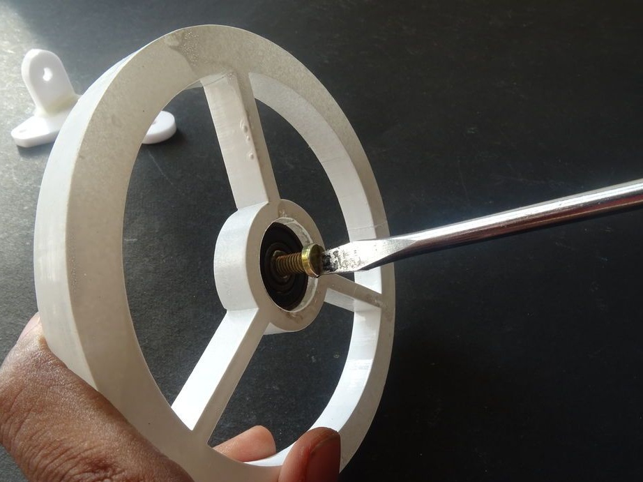
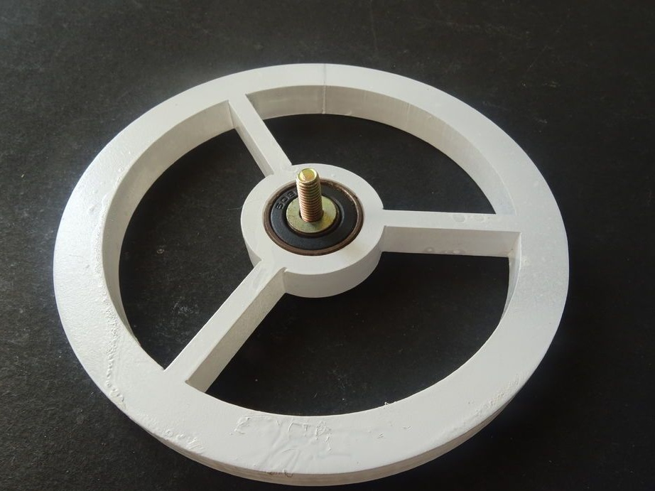
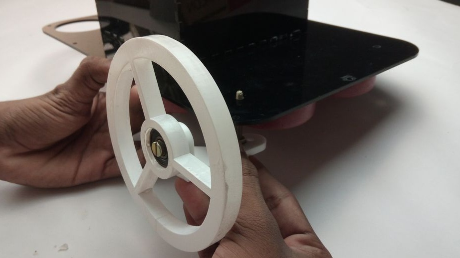
Step Eleven: Wheel Assembly
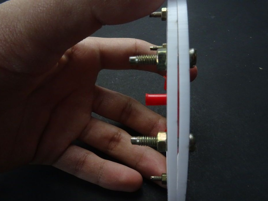
On bolts collects two wheel rims. The screws are not fully tightened.
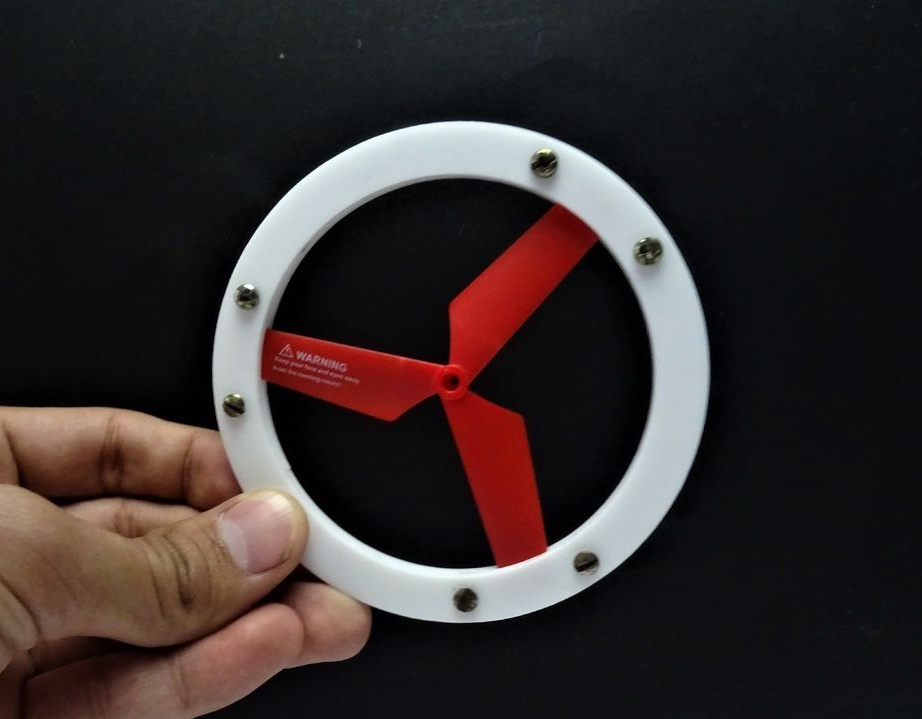
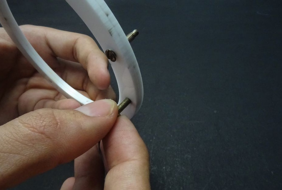
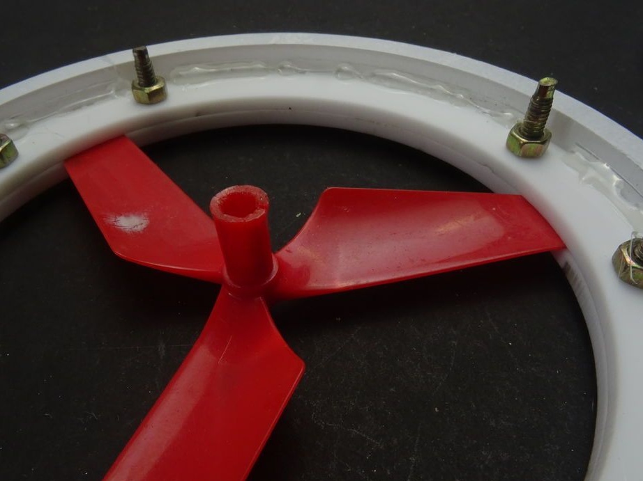
Between the disks installs screws and tightens the screws. When installing the screw, you must use the template to center it.
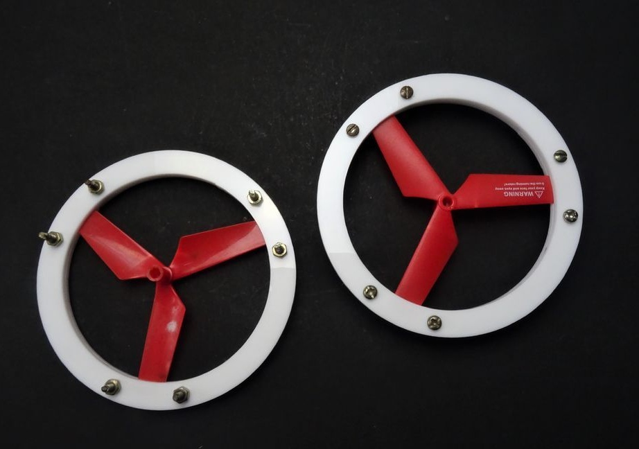
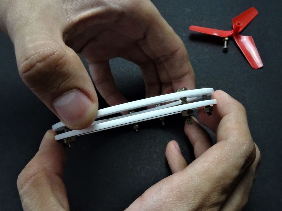
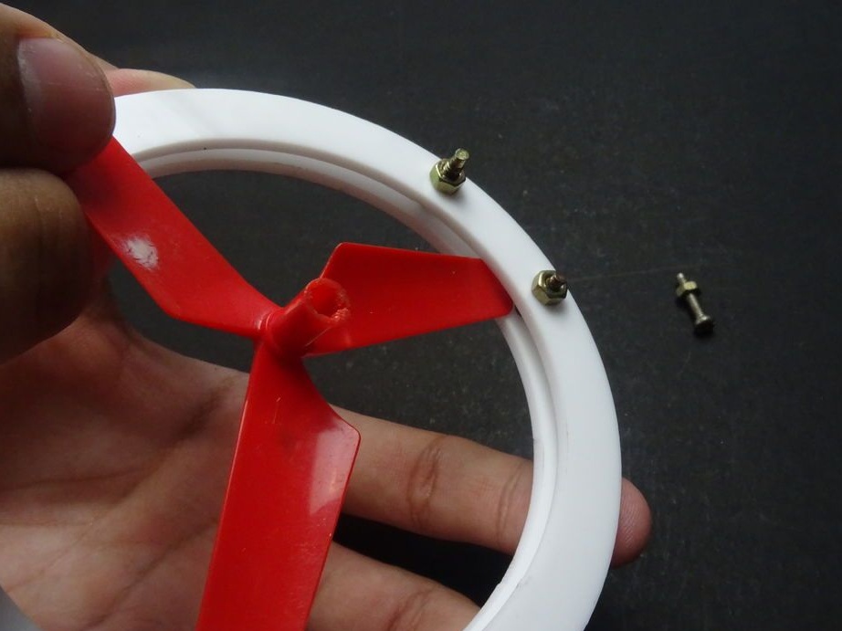
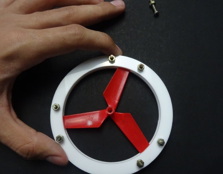
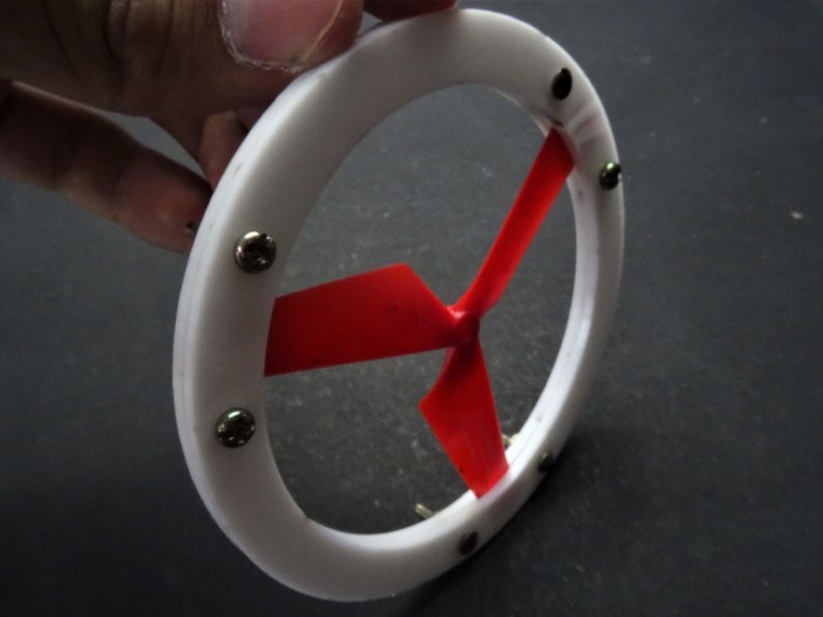
Sets the outer rim of the wheel. The rim must be flush with the internal disk.
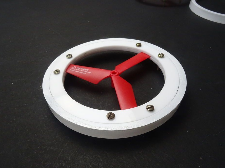
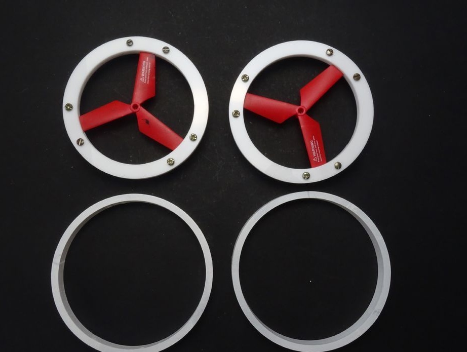
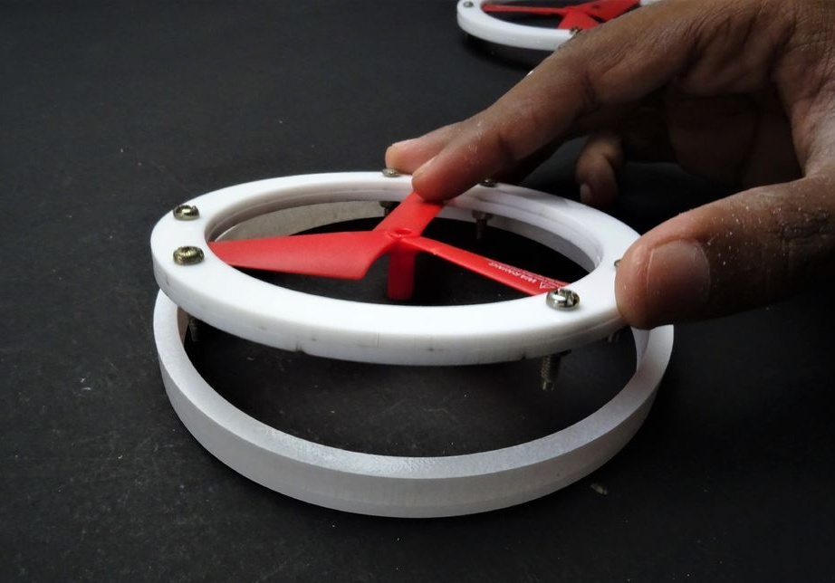
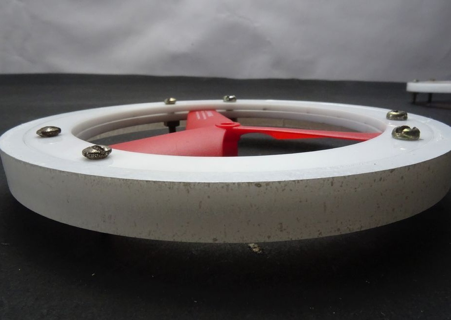
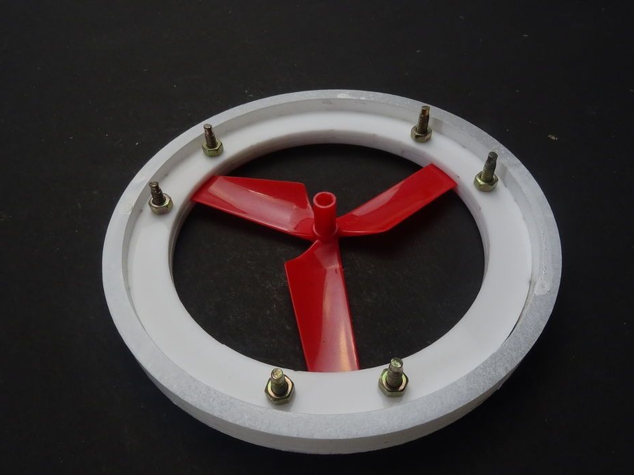
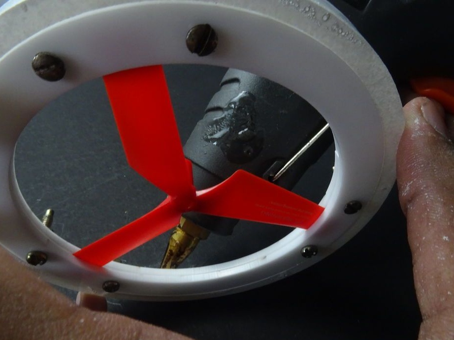
Apply hot glue to the joint.
Now collects the front wheels.
A nut of a suitable size clogs into the inner race of the bearing. Presses bearings into the front wheels.
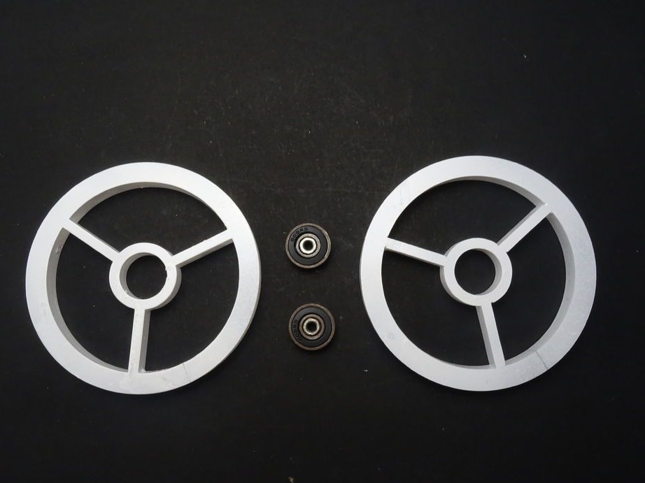
The wheels are ready.
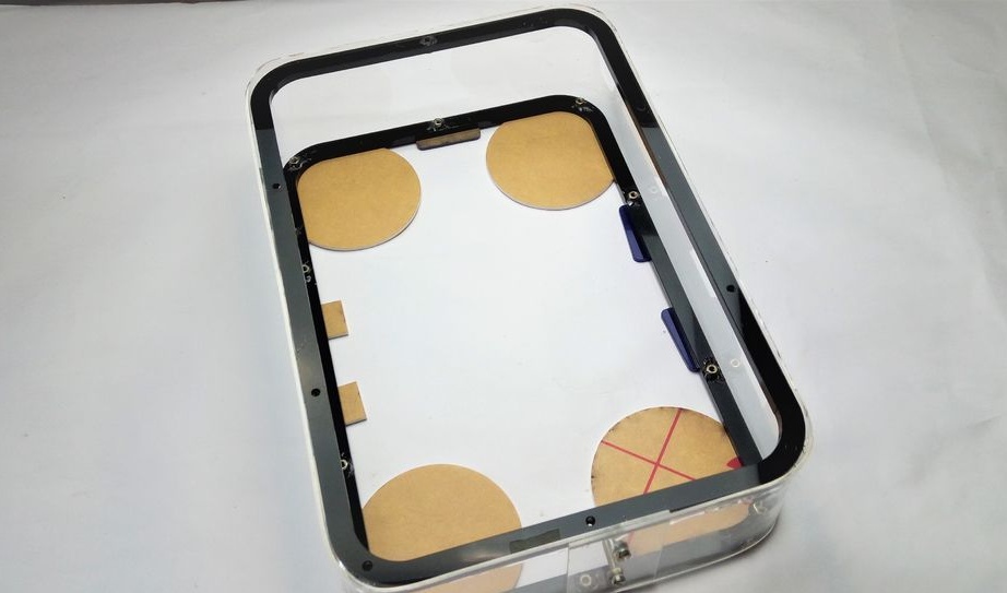
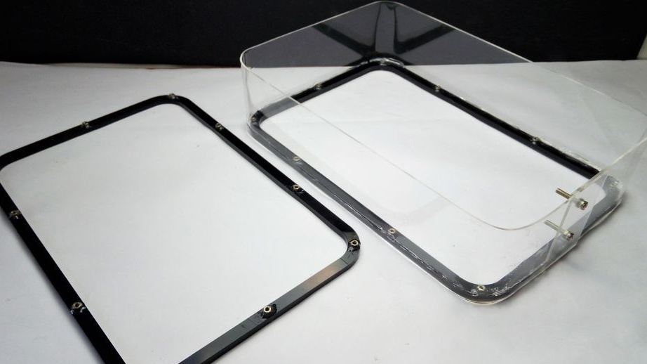
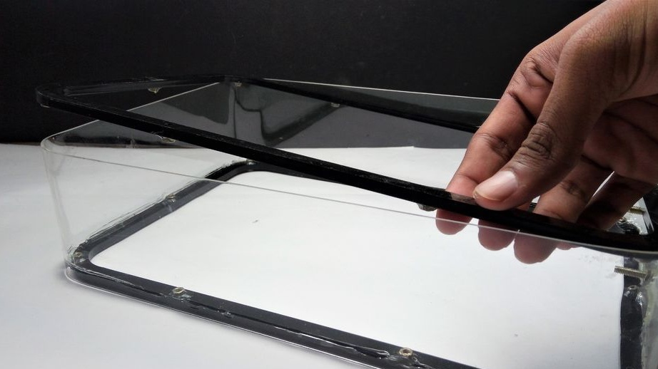
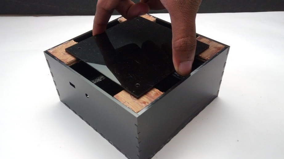
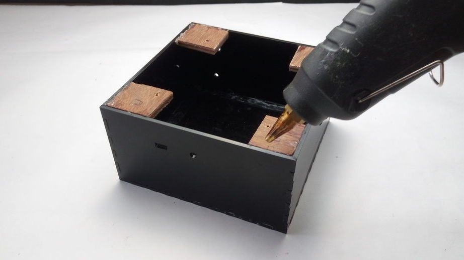
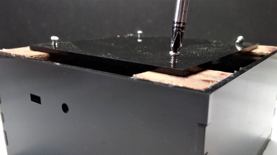
Step Twelve: Electronics Enclosure
Glues the housing for the electronics.
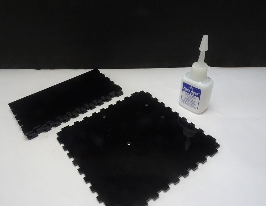
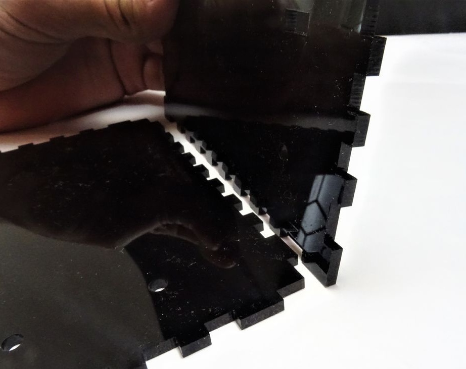
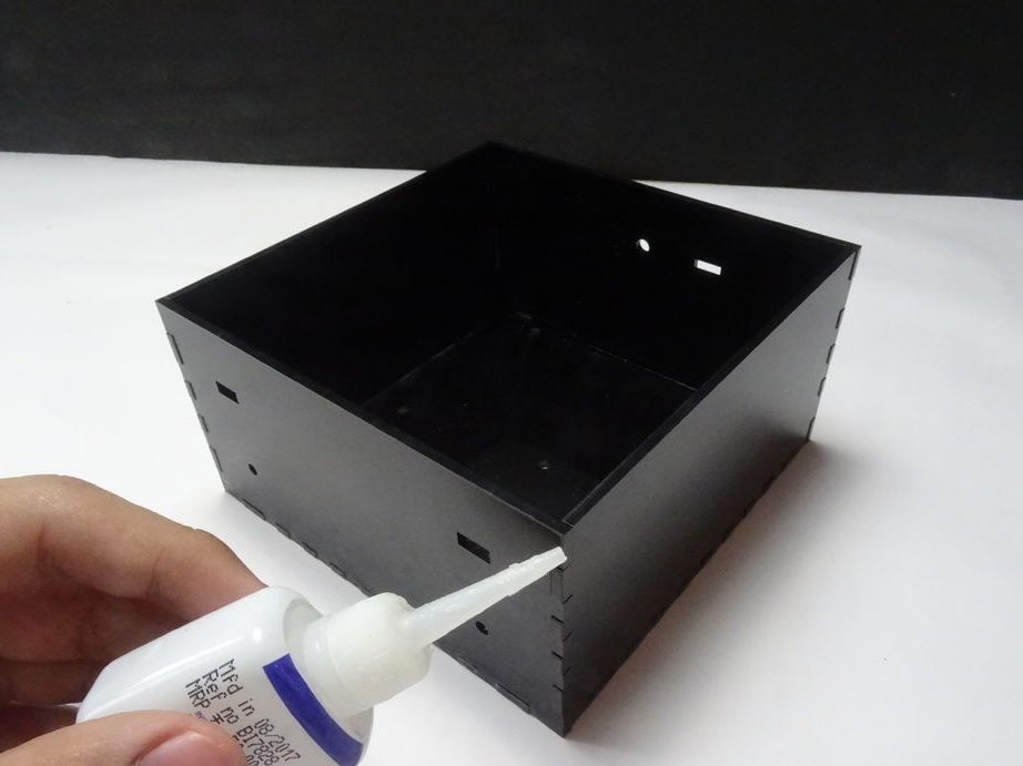
This box will contain everything electronic components, which means it needs to be waterproofed as thoroughly as possible.
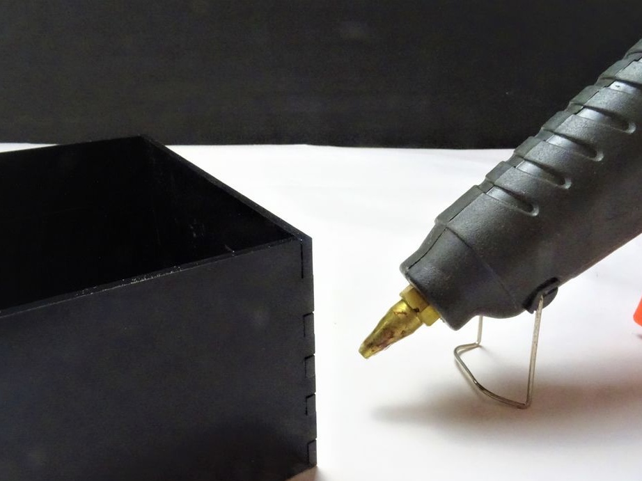
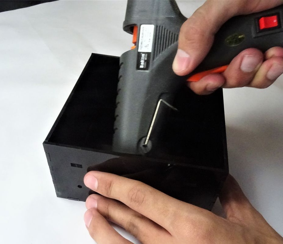
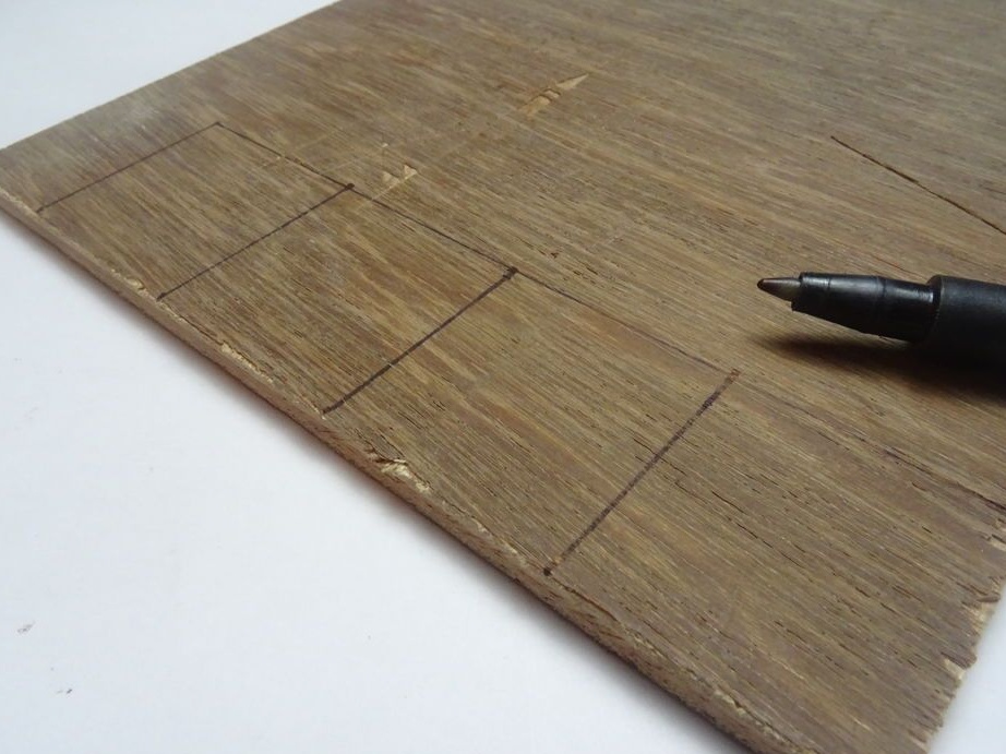
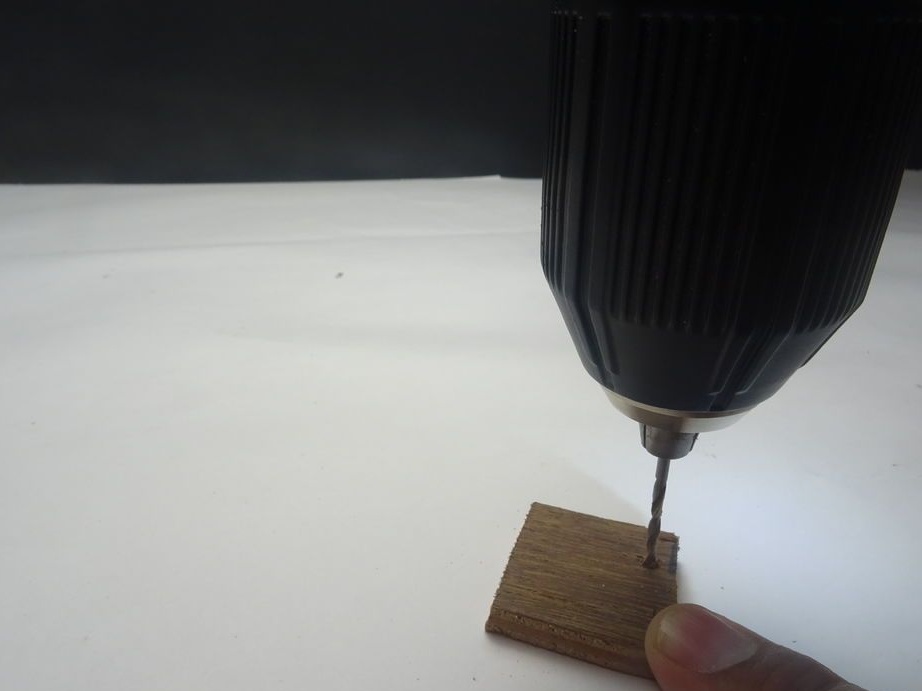
Four squares are cut and glued from the board in the corners of the box. The box lid will be attached to them.
Step Thirteen: Wheel Mount
Now you need to connect the wheels and gear with a clutch.
Screws front wheels to traction.
Step Fourteen: Connect Electronics
According to the scheme, it installs electrical parts.
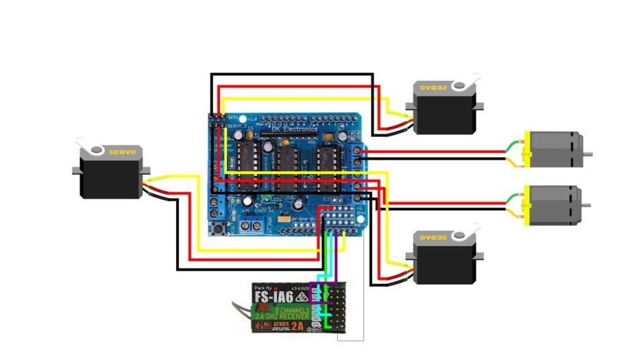
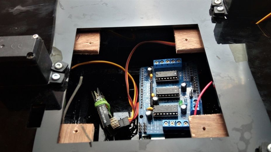
The wires of the left engine to M1, the right to M2. Connects an engine driver. Connects servos. Installs the receiver: gnd of the receiver to gnd Arduino; +5 V receiver to +5 V Arduino; pin 3 to A0; pin 1 to A1; pin 5 to A2. Connects the battery.
Step Fifteen: Download Code
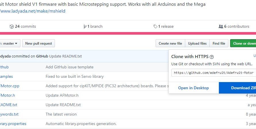
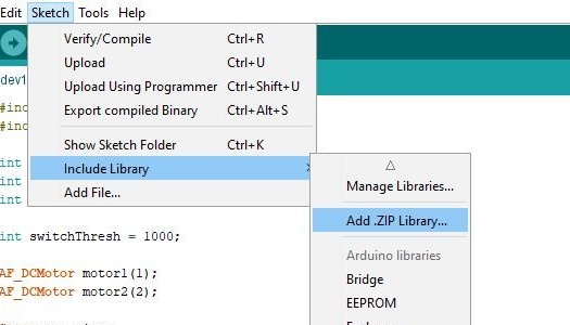
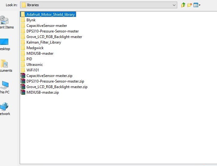
First you need to download the library.
Next, download the code. When loading, the battery should be disconnected.
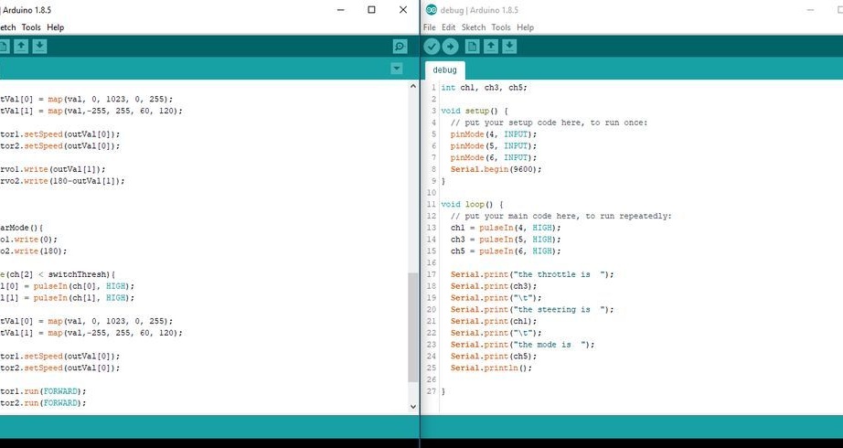
Download the code below.
amphibious_rover_code.ino
After downloading the code, it checks the operation of motors and drives.
Step sixteen: assembly
Now it's time to assemble the all-terrain vehicle.
[center[/ center]
Installs servos. Installs gear motors.
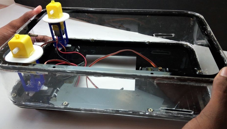
Fastens the wheels. Twists both halves of the body.

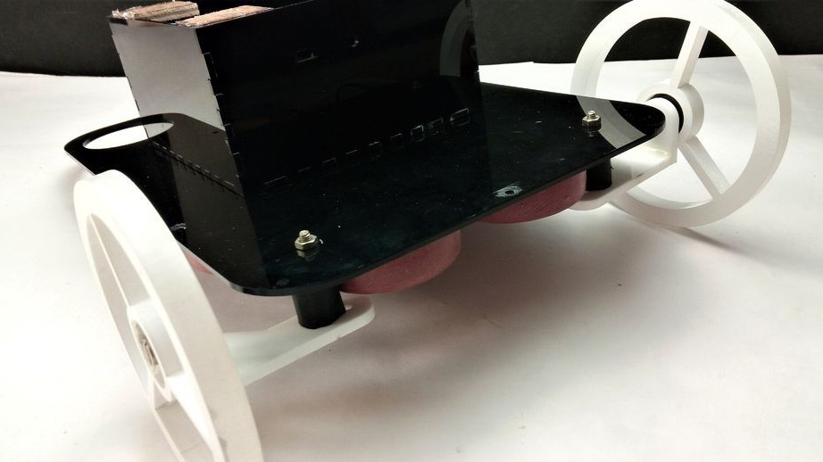
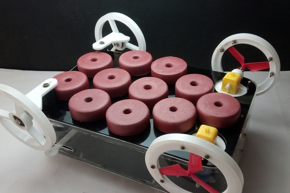
Everything is ready and now you can test.