This article will focus on the stun device for civil self-defense. The author of this homemade AKA KASYAN.
Attention! The author does not recommend this device for repetition and assumes no responsibility for your actions. The use and illicit trafficking of a self-made electroshock device is punishable by law!
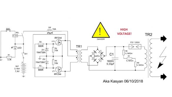
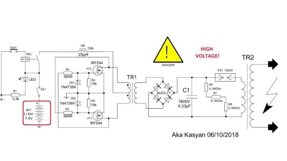
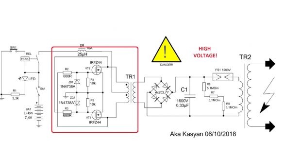
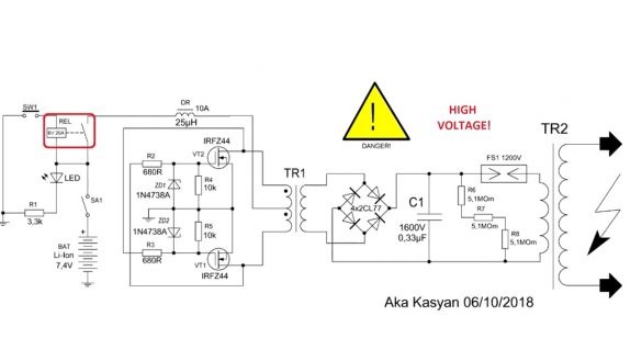
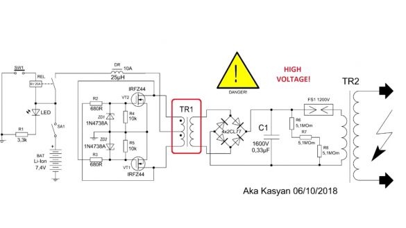
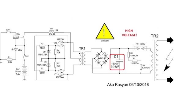
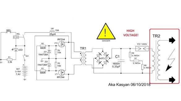
Well, now, without wasting time, get to work. The device diagram is now in front of you:
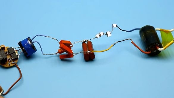
This is a classic stun gun circuit. The voltage from the power source is supplied to a boost converter circuit, the output of which gives a high voltage of high frequency. This voltage is rectified to a constant by a diode rectifier and accumulates in the capacitor. When the voltage on the capacitor is higher than the breakdown voltage of the spark gap or spark gap, the entire capacitance of the capacitor is discharged through the air breakdown to the primary winding of the high-voltage coil. On the secondary winding of the same coil we get a discharge with a voltage of about 50,000 V and higher (it all depends on the parameters of the coil).
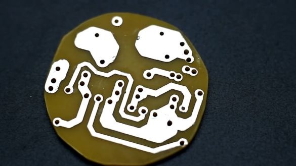
The author had to develop a small printed circuit board on which the components of the converter and the launch system are located.
It turned out crookedly, but it will not affect work in any way. And if you want your homemade boards to look like factory ones, then you should order them at the factory.
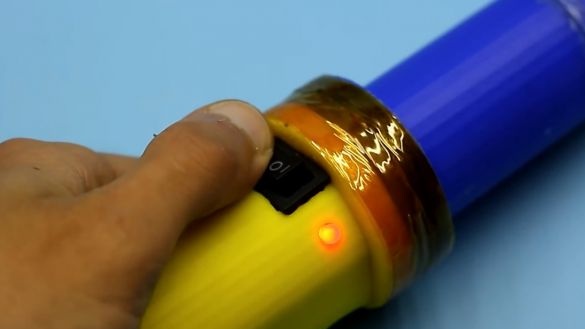
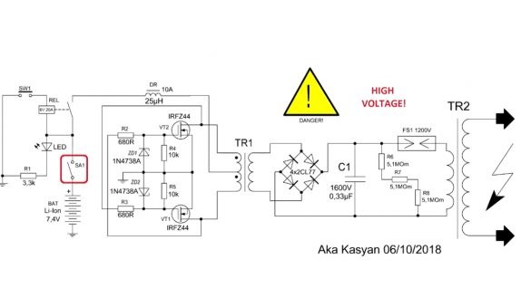
It is important to note that discharges cannot cause injury. They cause only pain shock, disorientation and muscle cramps, which do not last long. Such a shocker is not capable of harming health. It is this circuitry of an electroshock device that is used all over the world for the construction of both civilian and police electroshock devices. The power of this particular option lies in the range from 7 to 10 watts. The shocker has a two-position switch. The first mode is removal from the fuse. In this case, the red indicator LED lights up. It is necessary to press the button and the shocker will begin to crack.
The second position is the activation of the flashlight.It is not drawn on the diagram.
Body. 3d model Corps was developed by Dima from the YouTube channel “Household dialogue”.
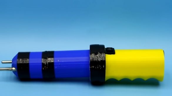
It remains only to print the case on a 3d printer. The wall thickness is selected so that the shocker is not afraid of bumps and falls, in general, you can safely use it as a baton. The handle is comfortable with finger recesses. The launch button of the device is hidden under the index finger. The color of the case is not the most suitable, but what the author was printing. Well, now move on to the filling.
Source of power - lithium ion.
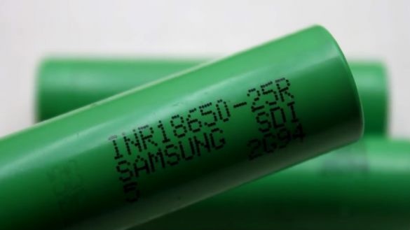
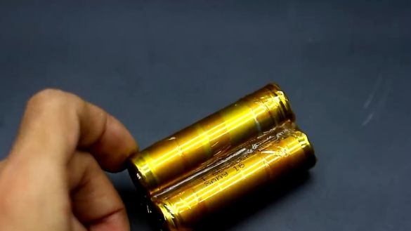
Two series-connected banks of the 18650 standard. In this homemade battery used from a laptop battery. It is these cans that can be discharged with currents of about 5A, but before installation, the author conducted several experiments, during which it turned out that they calmly tolerate 7-8A discharge current and up to 15A for 20 seconds. And so the author advises using these batteries, they are high-current, designed for vape, you can discharge 20-30A currents.
With the battery, I think everything is clear. It is worth adding only that the author removed the factory coating and replaced it with heat-resistant adhesive tape for reliability, and then connected the cans with nickel tape using the resistance welding method - all as expected.
The battery is ready. Battery protection system, of course it is needed. But it so happened that the author found a board with protection for 2 3A lithium-ion cans based on the HY2120 chip, and our circuit eats much more.
The author of course tried to increase the current protection of this thing. To do this, he developed his board, raising the protection current to 6A, but this was not enough. Therefore, a battery without any protection and balancing cards is bad, therefore the author has already ordered a board with the required current. In the meantime, the protection we have will be a relay that will not work if the battery is discharged below 6V.
High voltage converter.
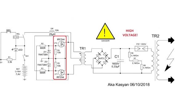
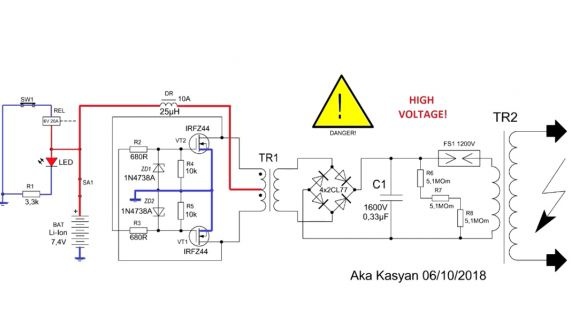
This is a push-pull boost generator of a self-generating type, built on the basis of powerful field-effect transistors. The shocker is equipped with a fuse. In order to avoid accidental switching on, you first need to turn on the device (the indicator for removing from the fuse lights up), then we press the button and the circuit starts.
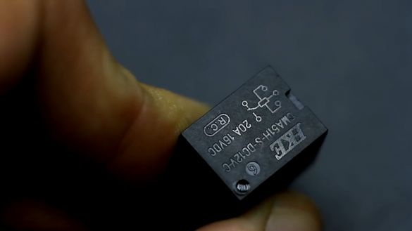
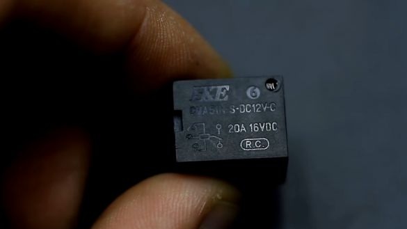
Very often, in homemade shockers, they use a start system based on a regular button, but the author always used a relay. The fact is that the circuit eats enormous currents from the power source, and finding compact buttons with a current of more than 10A is very problematic. Therefore, a low-power button is used, pressing of which supplies power to the relay winding.
The relay closes, and the main power supply is already flowing through the relay contacts. The voltage of the relay coil depends on the power source. The usual 12-volt relay of this kind works fine from a 6-7V source.
But if possible, put a relay with a voltage of 6V coil. The relay contacts are rated for a current of 20A.
Switch.
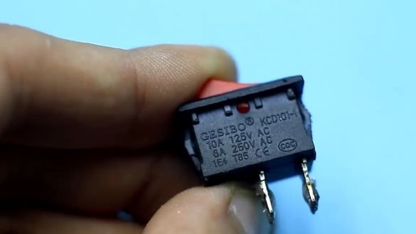
Finding a compact switch with a current of 10-20A is not a problem. Here is the most ordinary switch, such even in computer power supplies can be found. The converter circuit, as mentioned earlier, is built on the basis of 2 field keys.
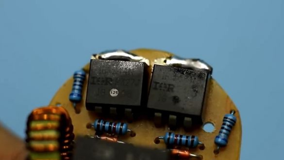
In this case, there are transistors irfz44. The gates of the keys are shunted to ground with resistors.
This helps the keys to some extent close, discharging the shutter. Zener diodes are used to protect the gates from overvoltage. They need to be taken with a stabilization voltage from 6.2V to 12V, preferably single-watt.
Gate limiting resistors take with a resistance of 330 ohms to 1 kOhm. You do not need to put the keys on the radiator, since the shocker is designed for short-term operation. Before assembly, make sure that all components are functional. And most importantly - check the transistors for authenticity, otherwise they may fly out at the first start.
The inductor is wound on a compact iron powder core. Wire 0.85 mm. The number of turns can vary from 12 to 20. The size of the ring is not critical, they can be found in the output parts of switching power supplies, they stand after the rectifiers.
Pulse transformer.
How to wind it is shown in this video:
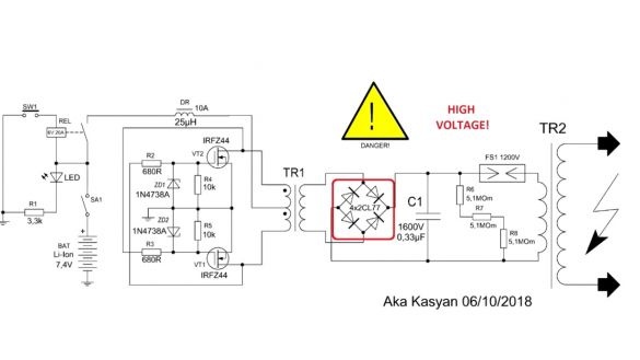
Next comes the rectifier.
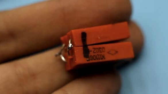
Here it is a full-fledged half-wave, in other words, an ordinary diode bridge.It was built on high-voltage diode poles of the Soviet model KTs106G, but there are a lot of imported analogues.
Diodes must be designed for reverse voltage from 6,000 to 10,000V, current at least 10 mA, must be able to work at frequencies of 20 or more kilohertz.
The storage capacitor is film, designed for a voltage of 1600-2000V, a capacitance of 0.15 to 0.47 μF (the larger the capacitance, the less often the discharges, but the more joules in one discharge).
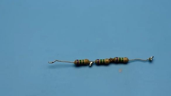
In parallel to this capacitor, a high-resistance resistor is connected to discharge the capacitors after the shocker is turned off.
Discharging resistors in this case 3. They are connected in series, the resistance of each lies in the range from 3.3 to 7 MΩ. This chain is hidden under heat shrink.
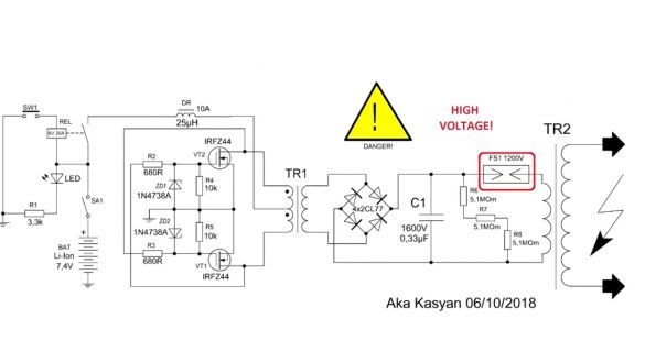
Spark gap.
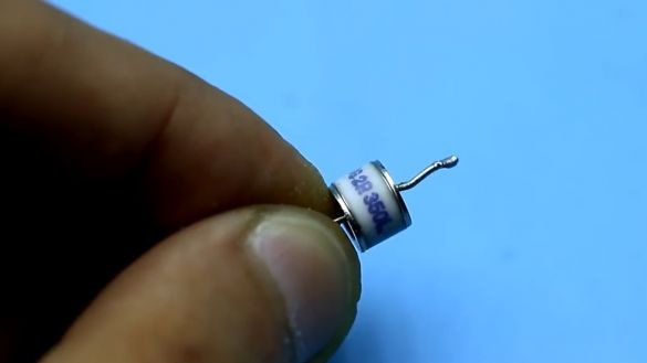
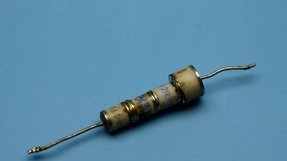
In fact, this is an air gap through which the capacitance of the capacitor is discharged to the primary winding of the high-voltage coil. The arrester is needed with a breakdown voltage of 1000-1500V. You can buy the necessary arresters or dig out from the xenon ignition blocks, but there the arresters are usually 350-400V. In order to get the arrester for the required voltage, the author connected several pieces in series.
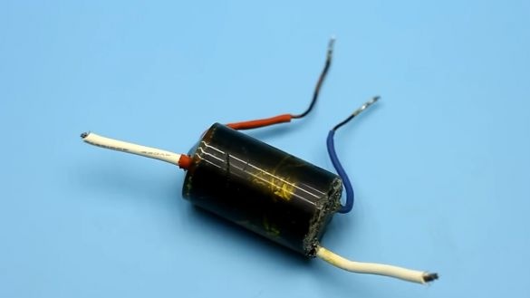
High voltage coil.
After complete assembly, you need to check the operation of the device.
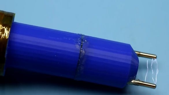
Further, the entire high-voltage part of the device was completely flooded with epoxy. Before pouring, all cracks were carefully sealed with hot glue.
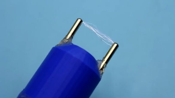
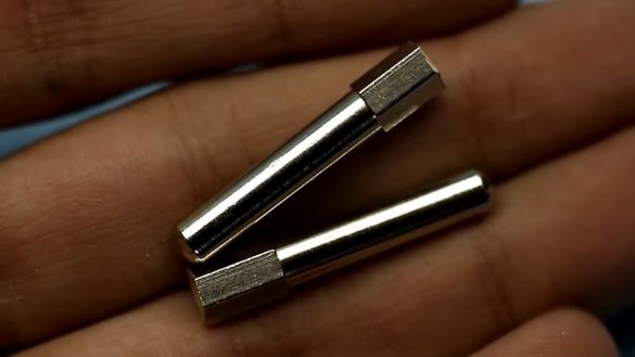
The author took the material for high-voltage bayonets from an ordinary plug - this is painted brass.
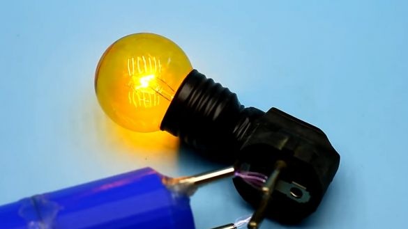
The device turned out pretty high-frequency. The frequency of sparking is about 100Hz. The discharges stretch to a length of 5 cm, but they are limited by bayonets, the distance between which is 3 cm.
The device is cracking quite scary, but as mentioned earlier, this stun gun can not cause serious harm to health. High tension causes uncontrolled muscle contraction, temporary paralysis and severe pain, but all this goes away within a few minutes. Full recovery of the muscle system occurs within 30 minutes, it all depends on the time and place of exposure.
Well, that’s all. Thank you for attention. See you soon!
Video:

