
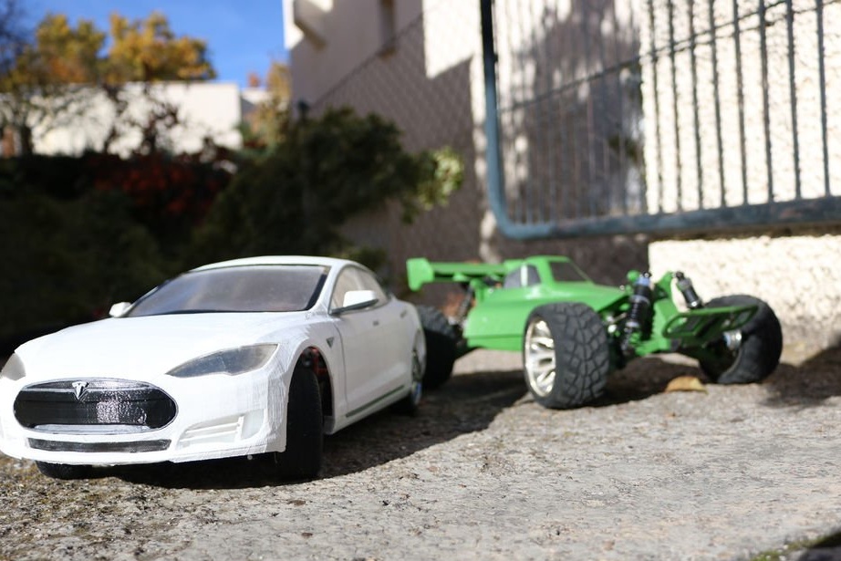
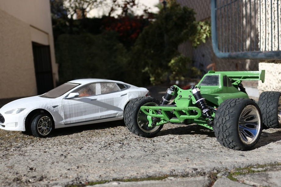
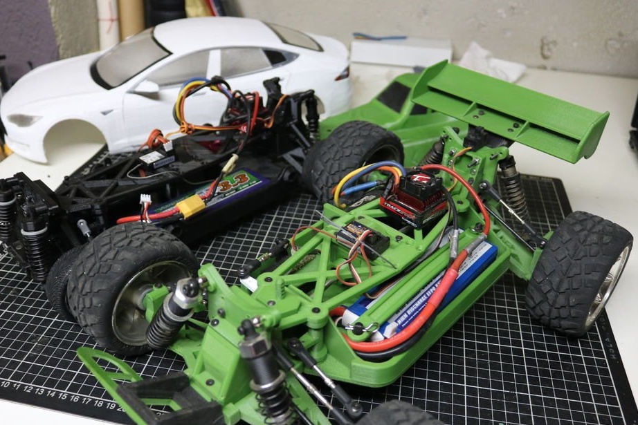
In this article, you will learn how to build your own RC (RC) car. The author did not stop, as far as possible, to improve some parts of the models. He made several videos and posted on his channel in YouTube.
If you are new to the RC world, you may not know what you need and what you really want; types of cars and their characteristics. Below is a summary table to help you make your choice.
After reading this article you can build Drifting, Touring, Rally, Buggy, Truggy or Short Course. In the first part of the table you will find the characteristics of the type of car. Some of the options depend on speed, clearance, wheel size and car.
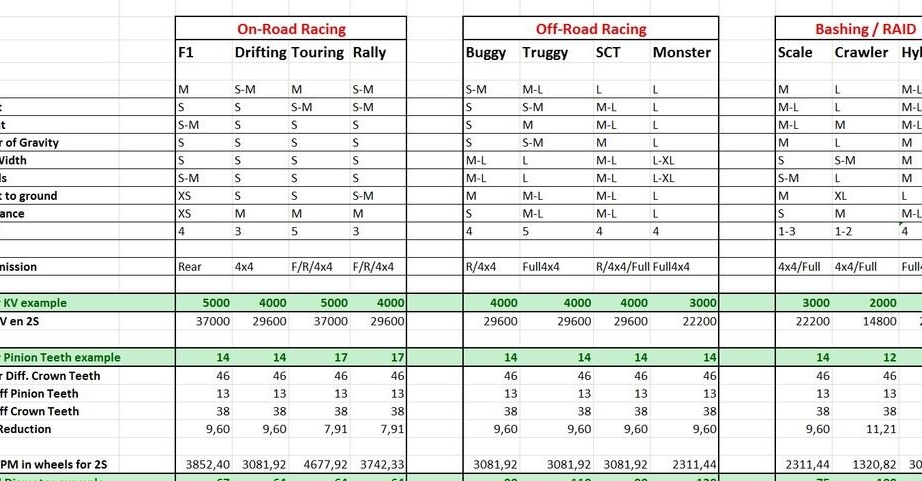
The second part of the table is the parameters needed to calculate the final maximum speed of each model. The three lines highlighted in green are those parameters that change to get maximum speed. By simply changing the ratio of the KV engine and the number of N teeth of the motor gear, you can get different model speeds.
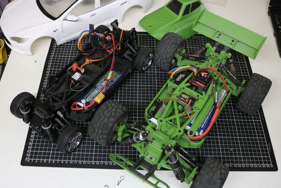
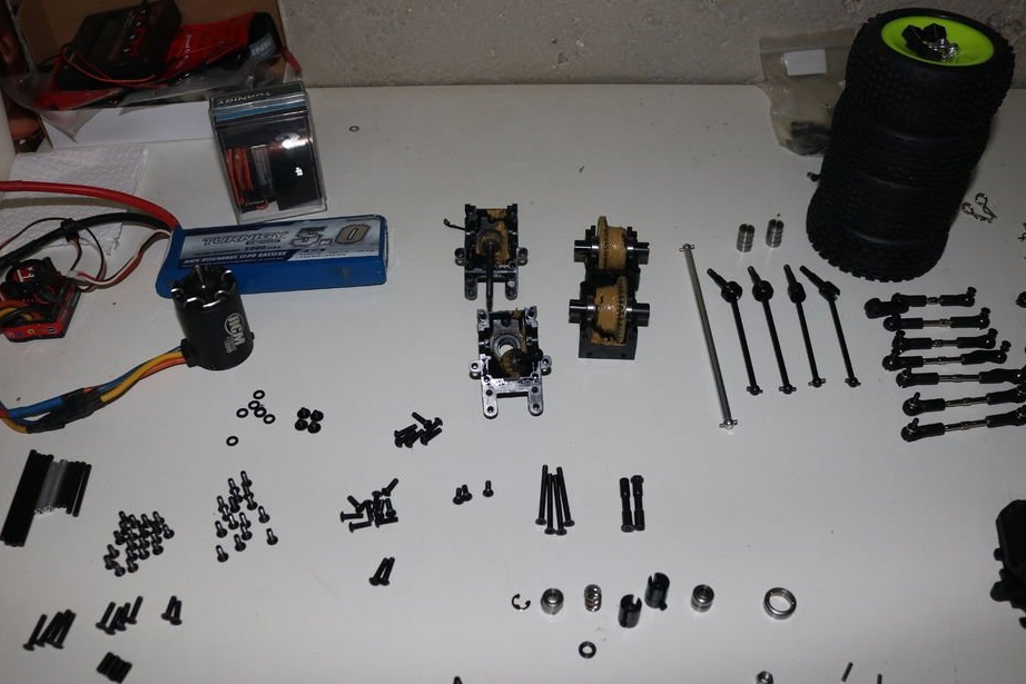
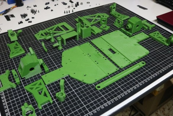
The parts you print will depend on the parts you buy. And those, in turn, will depend on the type of model that you will collect. Therefore, you must first think through everything before starting a “crazy print”.
Further, those details that will need to be purchased and the price range. So, for example, Motor (4-25-60) means that you can buy the cheapest collector motor for $ 4. A good brushless motor can cost $ 25. and finally, a powerful 3670 motor can cost $ 60.
• Receiver and transmitter (15-20-60)
• ESC Electronic speed controller (5-25-50)
• 3650 commutator / brushless motor or more for 1/10 (4-25-60)
• Servo 5-15KG (4-10-30)
• 2S LiPo Battery (9-15-25)
• LiPo Charging (5-12-40)
• Flashlights (4-8-20)
• Battery / Motor / ESC Shrink Adapter (0-2-10)
It will be $ 46 for the cheapest configuration, $ 117 for the good / recommended configuration, and $ 295 for the electronics configuration. Your task is to find the point where your desires meet with the possibility of your wallet.
But that is not all. You will need gears for differentials, bearings, axles.And of course we must not forget about shock absorbers.
• (shock oil) (8-15-40)
•
•
•
•
•
•
•
•
•
•
•
•
• [leechrl = https: //hobbyking.com/en_us/metal-flat-head-machine-hex-screw-m3x16-10pcs-set.html] many M3 bolts and 4 pcs self-locking nuts (6-12-30) [ / leech]
•
•
All links are for pricing.
Settings


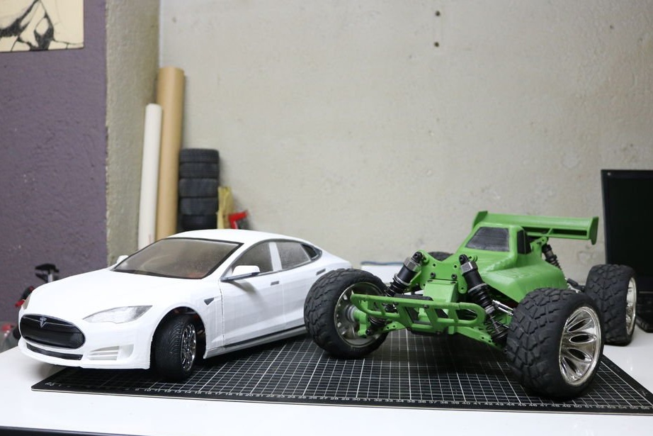
The selection of the original parts is the first setting, since the details depend on the type of car you want to build. The author of this project made a chassis for three types of cars On-Road, Buggy, Truggy. You can try to use the chassis from other projects. But then you have to adapt the wheelbase and axle width.
Wheelbase (Wheelbase) : distance between axles. You can create chassis with different wheelbases by choosing different parts for printing. Combine one front and one rear to have the final wheelbase matching the base you want to use. The length of the central platform depends on this. The wheelbase of many drift models is approximately 255 mm buggy and truggy 270 mm, Tesla Model S -295 mm.
Axis width (Wide of the axle): Distance between axle wheels. You will need to use short cardan shafts (CVD) and 3D printing levers for On-Road vehicles and longer ones for off-road vehicles.
Center differential (Center differential)- you can use different differentials 1/8, 1/10
The position of the central differential - you can place the casing of the central differential in the center of the chassis, or move 9.5 mm to the right.
Caster and wheel alignment - Caster refers to the longitudinal inclination of the axis of rotation of the wheel. You can adjust these parameters for each axis. The author recommends starting with 6º in front and 0º on the rear axle. These adjustments are made with the help of “adjustable steering pins”, which can be printed out, or use the 4.7 mm ball pairs from the list above.
Clearance - you can change this parameter using two different printed “butterflies” for road and off-road configurations. For this, levers of different lengths and holes in the "butterflies" are used.
Universal platform
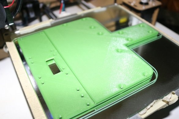
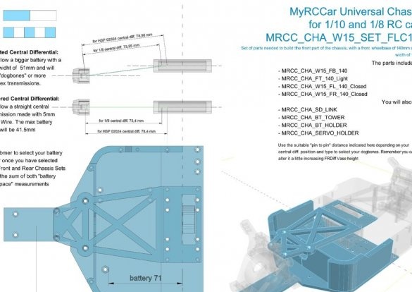
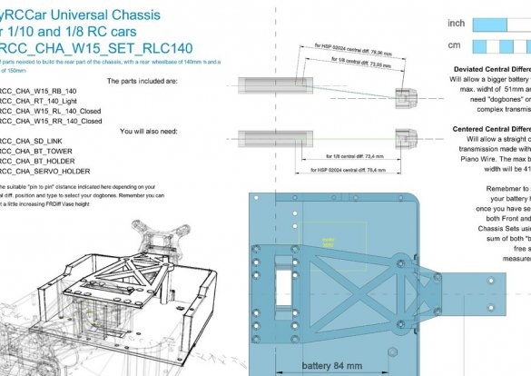
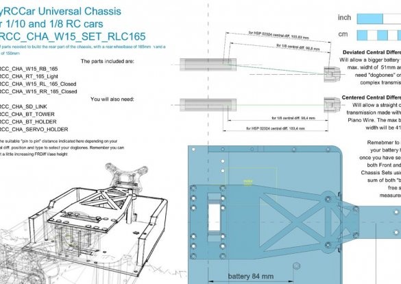
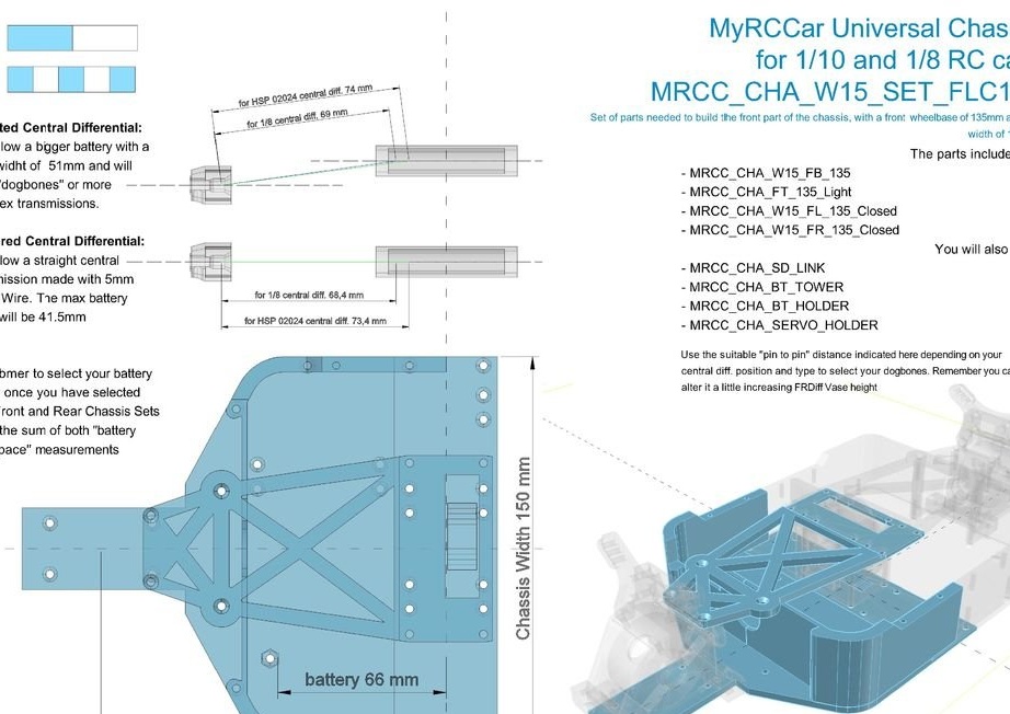
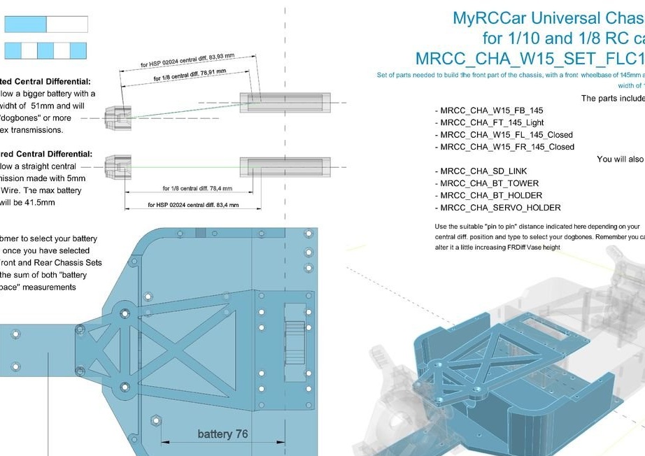
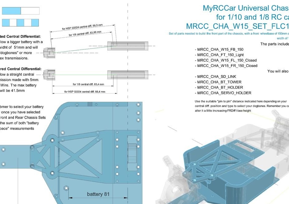
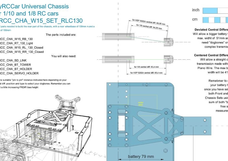
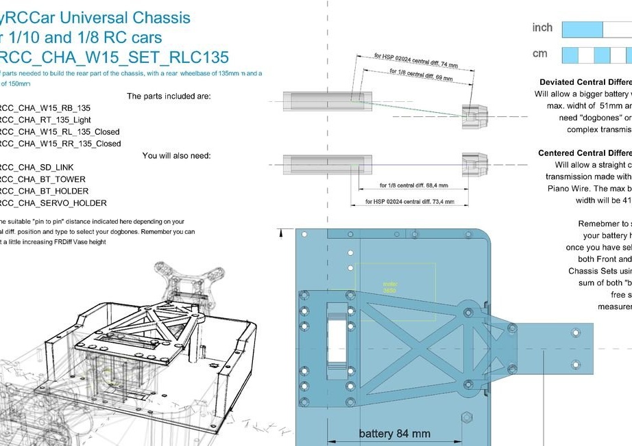
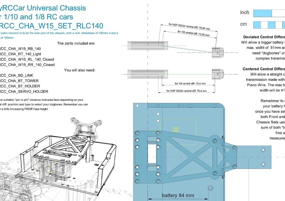
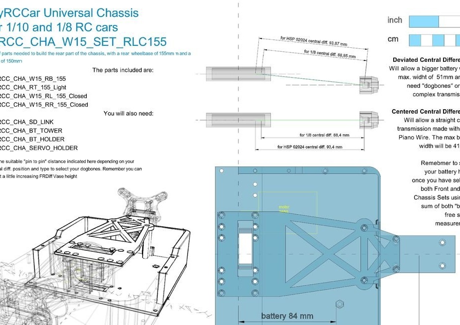
The platform allows you to build a chassis with a width of 115 mm and a wheelbase from 255 to 315 mm. Since the chassis is divided into two parts, the combination of these parts is the design key. In front of the chassis will be a servo, steering system and part of the battery. A motor, a part of the battery, and possibly some electronics will be installed on the back of the chassis. To choose the right front and rear chassis, you need to know the right wheelbase.
Your desired wheelbase = front wheelbase + rear wheelbase. As can be seen in the figures, the front wheelbase ranges from 135 to 150, and the rear - from 120 to 165.
• The four parts of the chassis are combined into one STL file, but a gap of 0.01 mm is left between them, which allows them to be easily separated after printing. For example: you want to build a car with a wheelbase of 270 mm. Select a 135 mm wheelbase and print the front and rear kit
• MRCC_OBTS_UP_W15_SET_FLC135.stl
• Bottom
• Top
• Sides
• MRCC_OBTS_UP_W15_SET_RLC135.stl
• Bottom
• Top
• Sides
If you are using parts from a set file, then print also two “side plates”. Remember plates do not need to be printed if you want to build a Frogger Build, Titan Build, or Tesla Model S Build.
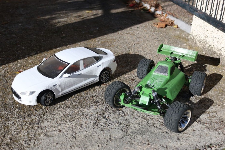
Shells for buggy, truggy, and on-road must be mounted on a chassis with a wheelbase of 270 mm for buggy and 295 mm for Tesla.
The drawings show that the maximum battery size is 150mm 66 + 84. You also need to print two brackets for the battery and servo.
• 2x MRCC_OBTS_UP_SD_LINK.stl
• 2x MRCC_OBTS_UP_BT_TOWER.stl
• MRCC_OBTS_UP_BT_HOLDER150.stl
• MRCC_OBTS_UP_SERVO_HOLDER.stl
All holes for M3 screws are 2.8 mm in diameter, 3.2 mm “pass-through" holes. All screws can be 16 mm long. For the center differential, you can use 30 mm bolts.
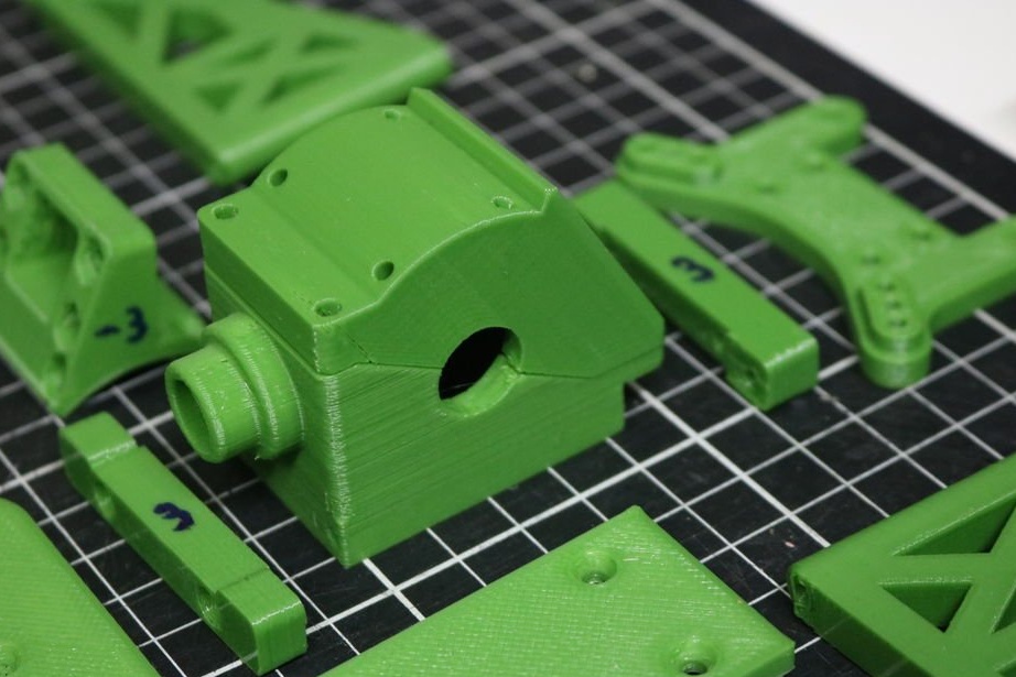
Front / rear differential
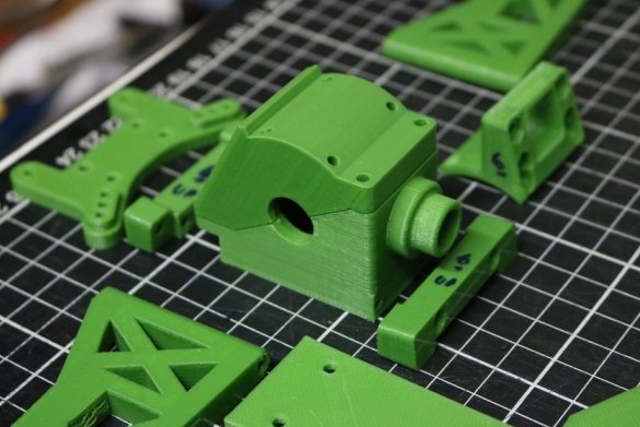

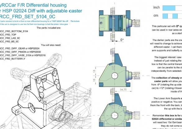
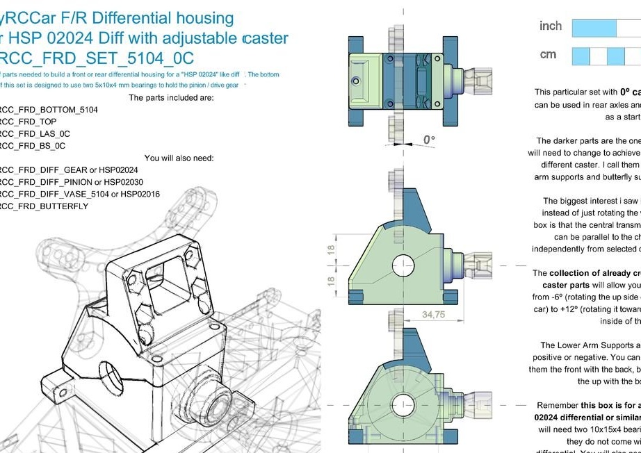
The differential cover is made for the “HSP 02024 Front Rear differential” or similar, because this differential is the most affordable in stores and is compatible with cheap Chinese counterparts.
An interesting feature of this casing is that it allows you to change the axis caster, changing only three small details when printing. The author tried 6º for the front and 0º or -3º for the rear axle. To do this, you need to print the desired lower support arms and support rack "butterfly".
You will need two 10x15x4 bearings to hold the differential in place, but some of the differentials purchased come with these bearings. You will also need two 5x10x4 bearings to lock the differential gear in place. In the same way, you will need one central drive shaft coupling 1/10 (1/10 universal cup / vase) for each gear.
There are two support stance "butterfly". A large one will allow you to install 80-100 mm shock absorbers for buggy / truggy, and a small one will install 60-80 mm shock absorbers for On-Road models.
To connect the lower and upper part of the casing, you will need one M3 nut and a countersunk screw M3x8-10. To place this casing on the main chassis, use M3 countersunk screws 12-14 mm long. You will need 4 for each differential case. this must be done to place part of the lower link caliper, which enters the inner side of the differential housing. Use the M3x16 countersunk head screws to attach the lower link caliper parts to the differential housing. For this you will need 8 screws.
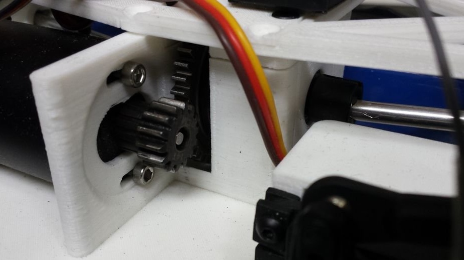
Center differential

You have two options for placing a central differential. Center the chassis or move it to the right to install a larger battery. Print the bottom and top of the box, the appropriate adapter for your differential. If you don’t want to spend $ 10 on an adapter and gear, then print out the attached gear Mod1 14T (made for trooper differential)
Once you have printed the adapter, you can place it on the chassis and screw it on the bottom with 5x M3x30 countersunk screws. They may be shorter, but in this way (30 mm) they help strengthen the chassis structure.
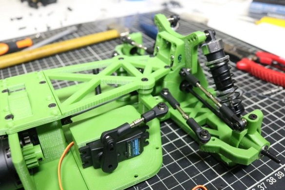
Steering gear
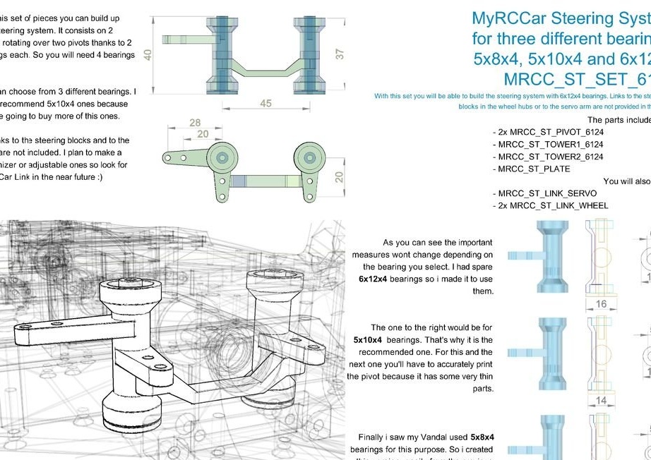
The steering system consists of two hinges and two “steering posts” above them. Both steering racks are connected by a steering draft. If one of the servo levers is rotated, the other does the same.
The steering system is designed for 3 different sizes of bearings. The author recommends using 5x10x4 if they are easy to find for you. You will need 4 pcs. 6x12x4 bearings would be better if you can get them for the same price. You need to print only 5 parts. Insert the bearings into the “steering racks” and fix the hinges on them. After that, you need to connect the racks and the front steering blocks and the servo mechanism. For this, 4.7 mm ball joints with M3 screws are used.
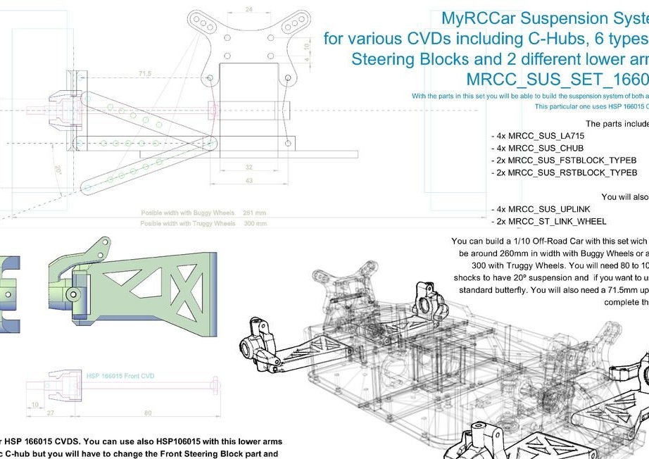
Suspension.
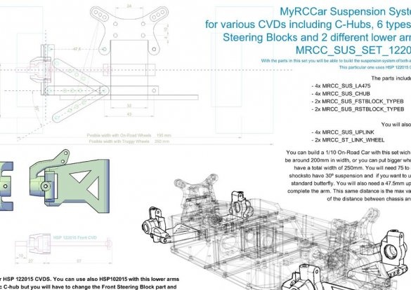
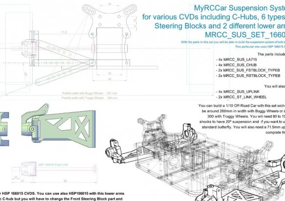
Now let's do the suspension. Suspension arms, steering units and rear fixed units other than the C-Hub will depend on the universal drive shaft (CVD) you want to use. And now again you have to choose from a large number of options. Perhaps the best solution would be to buy a CVD complete with a kit kit. Since HCP CVD is the cheapest, the author made different versions of parts for different HCP CVDs. These include 102015 and 122015 for short levers, 106015 and 166015 for ordinary long levers (version 715) and 108015 and 188015 for extended levers (version 769).
So now there is type ON-ROAD and OFF-ROAD. In combination with the corresponding C-Hub or RFBlock (RearFixedBLock), the ONROAD type allows you to install small wheels, while OFFROAD is tested for large wheels.
You will need a 3 mm steel wire (piano wire), from which you will cut the rod to 56 mm. 3 of them must be inserted into the holes of the levers. Also cut 4x33 (off-road) and 4x26 (on-road) rods and connect the C-hub or rear fixed blocks with levers.
Now it's time to put the lower link with the front C-hub in place. To do this, insert the rear part of the 3x56 mm rod (already in the lower link) into the hole of the lower link caliper, which you screwed onto the differential case earlier. Then use another lower link caliper and screw it (remember, 2 M3x16mm with sweat) to the differential cover.
If you are collecting front suspension arms, then you need to print 2 C-hub and two front steering units according to your CVD type. It will also be necessary to print two rear fixed units, according to the type of your rear axle. Below is a description of the steering blocks and rear fixed blocks:
• Type A: for Quanum Vandal CVD and Mission-D CVD
• Type B: for HSP 122015, 166015 and 188015
• Type C: for HSP 102015, 106015 and 108015
• Type D: for OpenRC Truggy Reely CVD
• Type X: for Vandal, rear axle shaft and sleeve
Now you must also select the correct leverage for your CVD as follows:
• 375 leverage for Mission-D CVDs
• 475 levers for HSP 102015 and 122015
• 715 levers for Vandal and Reely, HSP 106015 and 166015
• 769 levers for HSP 108015 and 188015
Now that you have printed the front steering blocks, insert the bearings into them and place them in the front C-Hubs. To do this, insert the front steering block almost to its final position and rotate around the axis, combining the holes of the steering block and the C-Hub. Use 2x M3x14-16 mm to secure the steering unit in place. After that, put the CVD in place (one side in the steering unit bearing and the other in the differential).
The camber is regulated by lower links. To have a 0 degree camber, use UAS_XXX with the same number as your lower links. You can choose a little longer or shorter to change the camber from 0º.
Print Files and Tips
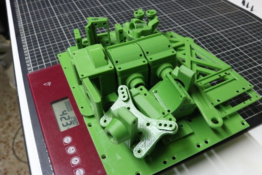
Files for printing are in the archive. Remember that you do not need to print all the parts, but only those that are needed for your assembly.
This project is intended for printing in FDM printers. All parts can be printed using the cheapest PLA you can find so as not to damage the printer.
Negative horizontal expansion is used (- 0.02.), Which allows printing mounting holes for bolts with sufficient accuracy. Although this is rather a feature of the author's 3D printer. Some parts are printed with supports that must be removed.
The author uses Annet A8. The basic settings for printing are as follows:
• Layer height 0.2 mm
• Perimeter thickness 0.48 mm
• 5/5 upper / lower solid layers
• From 15 to 50% filling with an overlap of 12%
• 210ºC at extruder temperature and 40ºC for the table (for standard PLA)
• Print speed 70 mm / s, speed 50% for external perimeters, speed 80% for filling and support
• The default speed of movement is 250 mm / s in XY
• Acceleration of the press of 300 mm / s2 and acceleration of movement of 400 mm / s2
• Retraction speed 60 mm / s, 2 mm retraction
• 0.23 mm when coasting at the end of the perimeter and 0.08 mm extrusion length of plastic before extrusion
• 0.2 mm Z-lift for retractions (to avoid some bumps and scratches)
• -0.02 horizontal expansion (for the correct size and size of the holes)
• First layer at a rate of 33% (for better adhesion and greater safety)
• I use a skirt at a distance of 8 mm from the object with 2 contours of 1 layer (to refuel the extruder and check the correct alignment of the table)
• 40-50% fan speed for the second and other layers (up to 70% for fast layers)
To print faster, the author increases the layer height to 0.25 mm and uses 4/4 top / bottom layers. To make the most part reinforced, it uses 3 or 4 perimeters instead of 2 and a minimum of 33% coverage.
Videos from models author:


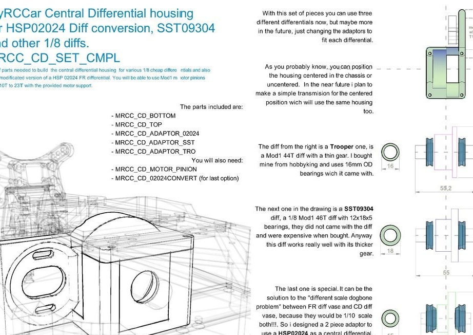


You have two options for placing a central differential. Center the chassis or move it to the right to install a larger battery. Print the bottom and top of the box, the appropriate adapter for your differential. If you don’t want to spend $ 10 on an adapter and gear, then print out the attached gear Mod1 14T (made for trooper differential)
Once you have printed the adapter, you can place it on the chassis and screw it on the bottom with 5x M3x30 countersunk screws. They may be shorter, but in this way (30 mm) they help strengthen the chassis structure.
Steering gear


The steering system consists of two hinges and two “steering posts” above them. Both steering racks are connected by a steering draft. If one of the servo levers is rotated, the other does the same.
The steering system is designed for 3 different sizes of bearings. The author recommends using 5x10x4 if they are easy to find for you. You will need 4 pcs. 6x12x4 bearings would be better if you can get them for the same price. You need to print only 5 parts. Insert the bearings into the “steering racks” and fix the hinges on them. After that, you need to connect the racks and the front steering blocks and the servo mechanism. For this, 4.7 mm ball joints with M3 screws are used.
Suspension.
Now let's do the suspension. Suspension arms, steering units and rear fixed units other than the C-Hub will depend on the universal drive shaft (CVD) you want to use. And now again you have to choose from a large number of options. Perhaps the best solution would be to buy a CVD complete with a kit kit. Since HCP CVD is the cheapest, the author made different versions of parts for different HCP CVDs. These include 102015 and 122015 for short levers, 106015 and 166015 for ordinary long levers (version 715) and 108015 and 188015 for extended levers (version 769).
So now there is type ON-ROAD and OFF-ROAD. In combination with the corresponding C-Hub or RFBlock (RearFixedBLock), the ONROAD type allows you to install small wheels, while OFFROAD is tested for large wheels.
You will need a 3 mm steel wire (piano wire), from which you will cut the rod to 56 mm. 3 of them must be inserted into the holes of the levers. Also cut 4x33 (off-road) and 4x26 (on-road) rods and connect the C-hub or rear fixed blocks with levers.
Now it's time to put the lower link with the front C-hub in place. To do this, insert the rear part of the 3x56 mm rod (already in the lower link) into the hole of the lower link caliper, which you screwed onto the differential case earlier. Then use another lower link caliper and screw it (remember, 2 M3x16mm with sweat) to the differential cover.
If you are collecting front suspension arms, then you need to print 2 C-hub and two front steering units according to your CVD type. It will also be necessary to print two rear fixed units, according to the type of your rear axle. Below is a description of the steering blocks and rear fixed blocks:
• Type A: for Quanum Vandal CVD and Mission-D CVD
• Type B: for HSP 122015, 166015 and 188015
• Type C: for HSP 102015, 106015 and 108015
• Type D: for OpenRC Truggy Reely CVD
• Type X: for Vandal, rear axle shaft and sleeve
Now you must also select the correct leverage for your CVD as follows:
• 375 leverage for Mission-D CVDs
• 475 levers for HSP 102015 and 122015
• 715 levers for Vandal and Reely, HSP 106015 and 166015
• 769 levers for HSP 108015 and 188015
Now that you have printed the front steering blocks, insert the bearings into them and place them in the front C-Hubs. To do this, insert the front steering block almost to its final position and rotate around the axis, combining the holes of the steering block and the C-Hub. Use 2x M3x14-16 mm to secure the steering unit in place. After that, put the CVD in place (one side in the steering unit bearing and the other in the differential).
The camber is regulated by lower links. To have a 0 degree camber, use UAS_XXX with the same number as your lower links. You can choose a little longer or shorter to change the camber from 0º.
Print Files and Tips
Files for printing are in the archive. Remember that you do not need to print all the parts, but only those that are needed for your assembly.
This project is intended for printing in FDM printers. All parts can be printed using the cheapest PLA you can find so as not to damage the printer.
Negative horizontal expansion is used (- 0.02.), Which allows printing mounting holes for bolts with sufficient accuracy. Although this is rather a feature of the author's 3D printer. Some parts are printed with supports that must be removed.
The author uses Annet A8. The basic settings for printing are as follows:
• Layer height 0.2 mm
• Perimeter thickness 0.48 mm
• 5/5 upper / lower solid layers
• From 15 to 50% filling with an overlap of 12%
• 210ºC at extruder temperature and 40ºC for the table (for standard PLA)
• Print speed 70 mm / s, speed 50% for external perimeters, speed 80% for filling and support
• The default speed of movement is 250 mm / s in XY
• Acceleration of the press of 300 mm / s2 and acceleration of movement of 400 mm / s2
• Retraction speed 60 mm / s, 2 mm retraction
• 0.23 mm when coasting at the end of the perimeter and 0.08 mm extrusion length of plastic before extrusion
• 0.2 mm Z-lift for retractions (to avoid some bumps and scratches)
• -0.02 horizontal expansion (for the correct size and size of the holes)
• First layer at a rate of 33% (for better adhesion and greater safety)
• I use a skirt at a distance of 8 mm from the object with 2 contours of 1 layer (to refuel the extruder and check the correct alignment of the table)
• 40-50% fan speed for the second and other layers (up to 70% for fast layers)
To print faster, the author increases the layer height to 0.25 mm and uses 4/4 top / bottom layers. To make the most part reinforced, it uses 3 or 4 perimeters instead of 2 and a minimum of 33% coverage.
Videos from models author:

