

There are several reasons to equip system units of personal computers with water cooling. One of the most important is to reduce or completely get rid of the noise of fans blowing radiators. For a domestic indoor computer, in some cases working around the clock, this is important - a buzz at work is very uncomfortable. There are several hot spots in the system unit that require cooling, and if replacing a radiator with a blower fan with a water heat exchanger for the central processor and several large CHIPs is not particularly difficult, then upgrading the power supply unit is very rare.
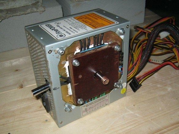
The following is a description of such a rework of a regular switching power supply for the system unit of a home computer. For this purpose, a water heat exchanger of its own design has been installed in place of a large fan, all powerful transistors and diode assemblies from air-blown radiators have been transferred to it. It should be said that in addition to the elements located on the radiators, pulse transformers and chokes are also heated in a switching power supply. General blowing somewhat cools them. It should be understood that by removing the fan, we deprive them of this cooling, however, observations of a long-running device showed that the metal case of the device heats up very slightly, from which it was concluded that this mode of operation is permissible in the existing configuration.
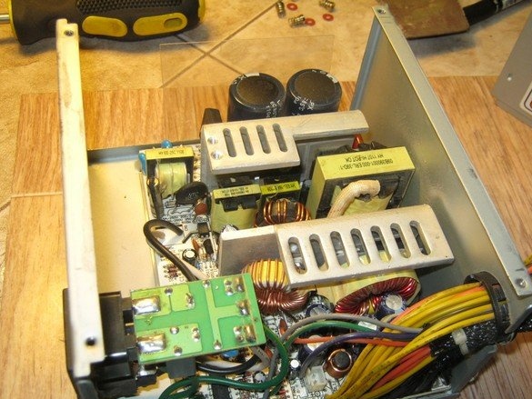
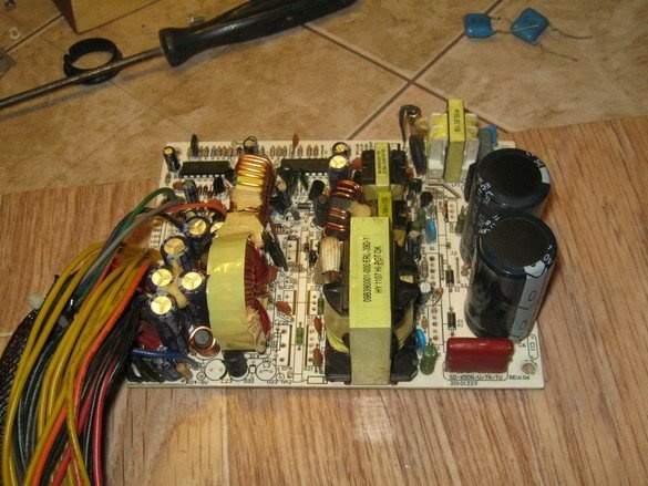
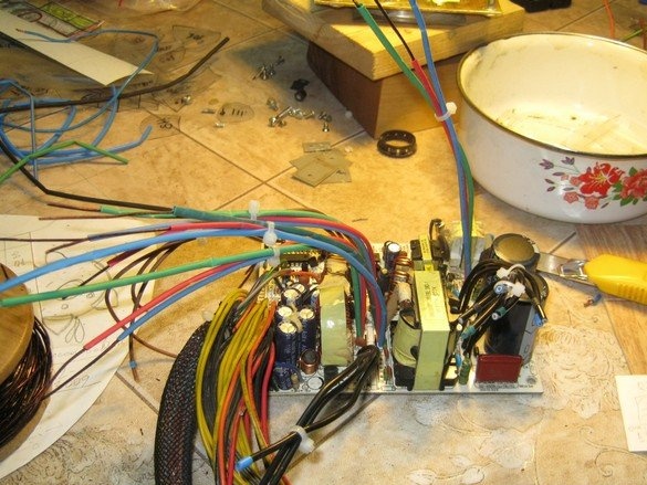
In the photo - a typical PSU without the upper half of the case. The textbook fan layout, what can I say. In fairness, it should be said that there are power supplies in nature specially designed for use with water or passive (a huge radiator-wall without fans) cooling - all the heating elements in it are pressed against one wall-heat sink. We have to work with what we have.
Dismantling regular radiators
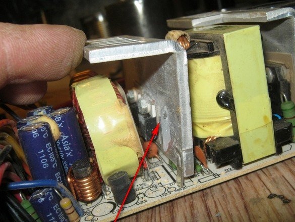
The power supply, unfortunately, is extremely compact, its powerful elements are adjacent to very delicate ones and it is very easy to damage the latter when dismantling it - any applied effort, a tool breaks or something like that. In addition, a very dense soldering "from below", where, nevertheless, you have to wield a powerful soldering iron. It seems that the unit is in principle not intended for repair.In a word, accuracy and accuracy again.
It is not difficult to say how the elements are mounted on the radiator - they are all set according to the template, the legs of all the elements are threaded into the required holes and everything is sealed. How to make out all this is a question. Unfortunately, such a useful thing as a desoldering pump was not at hand, but the high density of installation did not seem to give him a chance either. Collectively removing a block with 17 spaced legs without soldering everything around is somewhat difficult. I had to divide into components diode assemblies of three legs each, mechanically. These can be removed easily. Fortunately, along the fasteners of the elements, on the board, a sort of corridor was formed, where it was possible to act with a blade from a hacksaw for metal. Having cut off the caps of the screws, he tucked these TO-220s with a flat screwdriver and, removing it from the rest of the screws, soldered one at a time. After sawing each element, carefully blowing the board with compressed air.
Crossed to the other side, there were three elements, two also in the TO-220 and one larger. Diode assemblies are pulled back to back through the radiator plate, but this does not reduce the hassle - the radiator also has a thread and you have to cut off the cap on one side and the nut on the other.
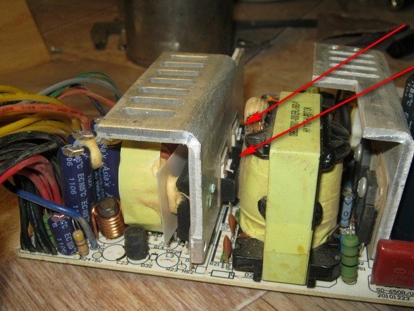
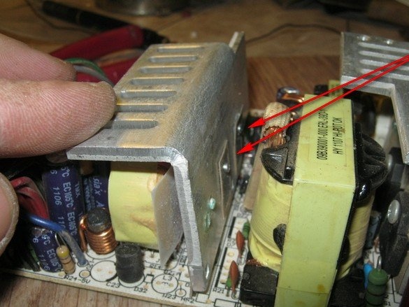
Finally, it was possible to unsolder the radiator of the low voltage part itself. Let's proceed to the high-voltage, it is simpler - only three elements.
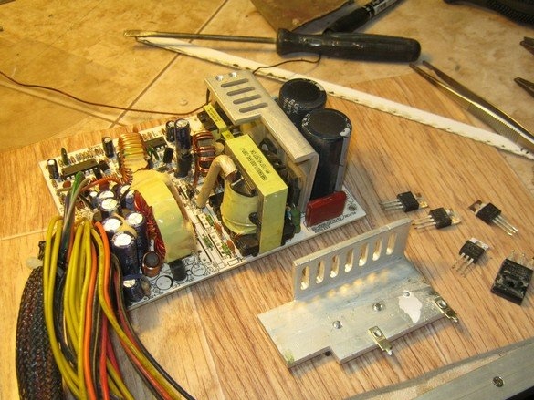
Voila! Radiators with the attached elements were removed, all the little things around were alive and well, the printing pads were put in order.
Making a water heat exchanger
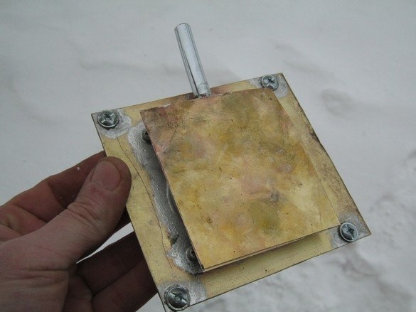
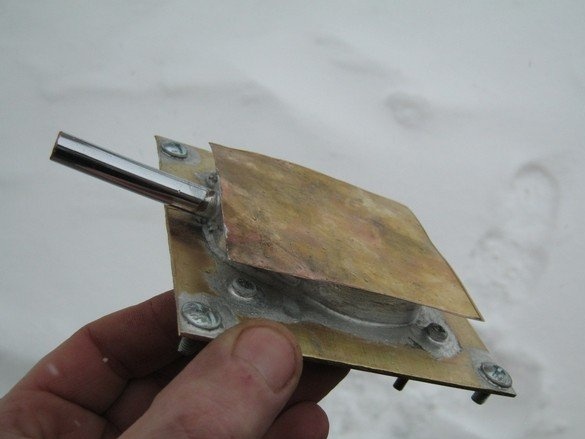
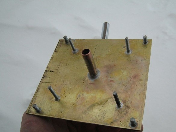
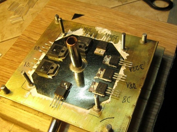
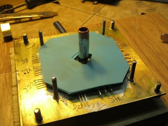
Made by technology tested on significantly smaller heat exchangers for the processor and chip of the video card and rigidly fixed in place of a regular fan on the unit cover. All screws are soldered to the bottom of the heat exchanger so that they can be tightened on one side. One set of screws is intended for fastening the heat exchanger itself, the second for pressing the plate holding elements. The internal structure of the heat exchanger and it is ready, in the photo below.
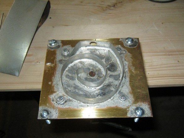
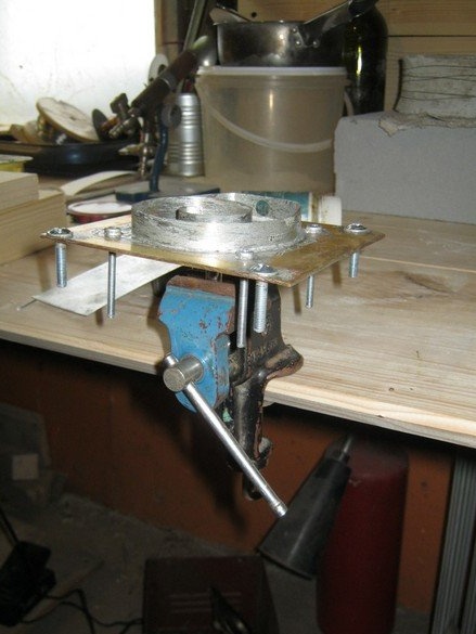
In the assembled heat exchanger, the screw lengths are specified and the excess is cut off. The heat exchanger fasteners are fitted to the ears of the power supply housing. From a piece of thick getinaksovoy plate made mounting clamping devices to the heat exchanger. After fitting, the getinax mount was coated with nitro-varnish - the material is very porous, respectively hygroscopic. Painting or varnishing overlap the pores and neutralize this disadvantage, although in this case, it is rather just a good tone.
Mounting
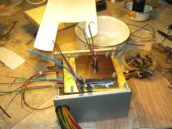
We proceed to unite all this in a single design. In place of each element soldered from the power supply board, we solder a sort of extension cord - a piece of wire of sufficient cross section. At this stage, it is important to mark each wire because when soldering the ends, the board with its “tips” will not be visible. My wires are marked like this - three wires from each element are combined into groups with a disposable plastic screed, each wire in the group is marked with a piece of colored thermotube. By far, the best way is when you have a large selection of mounting wire and you can choose pieces with different colors of insulation.
It does not hurt to make several large photo montages.
The low-voltage part is high-current - wires are required a significant cross-section. Part of my wires is a thick winding wire insulated from a heat pipe. This allows you to save a large cross section and at the same time fit into a regular hole on the board, although the wires are quite stiff, which complicates the installation.
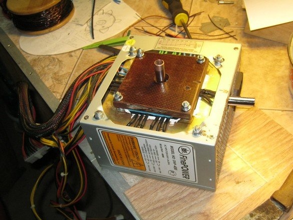
All elements requiring forced cooling are placed on the water heat exchanger through a mica pad. The gasket is quite thick - usually it was necessary to split it with a blade into two or three layers, here, for better reliability, the mica was left in its original form.Under the gasket and each case of the device, KTP-8 is coated with a thin layer. Each device is signed with an alcohol felt-tip pen and the entire sculptural group is covered with two layers of a thin silicone rug to neutralize small deviations of the thickness of the cases. A layer of silicone gasket turned out to be about 1 mm.
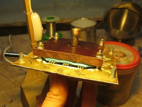
A rigid plate of getinax is put on over the elastic gasket, fastening screws - M4, washers, stoppers, everything is just like in people. Having carefully pulled the conclusions, it is possible and necessary to check the degree of pressing of the elements. Everything turned out to be in order, each building was pressed more or less, deserters and draft deviators were not found. We place the heat sink assembly at the place of service and proceed to the wiring of the conclusions.
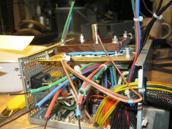
The conclusions were formed in a sort of S-shaped manner, so that after all rations, the heat sink could be moved within certain limits. In general, the piece of iron was practically in its place and we are talking about 10 ... 15 mm, which are needed for orientation and installation in loops from a regular fan. Installation is usual, the necessary three wires were put into circulation - the technological plastic clamp was cut off, the wires were formed, their length was specified, the excess was cut off. The ends were cleaned from isolation, tinned, soldered to the desired output of the element, isolated with a piece of thermotube pre-dressed on the wire. And so 24 times, but where to go?

Lastly, carefully blow out the block in different positions with compressed air. We dress the upper part of the casing of the power supply, from the inside we insert the screws of the heat exchanger into the petals on the body, washers, stoppers, nuts.
conclusions
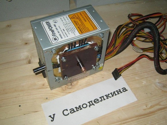
The power supply works well, the metal case heats up barely noticeable. Nevertheless, I do not presume to recommend such a design for repetition - the work requires a fair amount of electrical installation practice and is associated with a high risk of damaging a rather expensive device. In addition, the block, initially unsuitable for repair, turns generally the devil knows what.
Babay Mazay, January, 2019