

Greetings to all who have hands in place and sympathizers.
Today we will talk about a small grinding machine, based on the KD-30-U4 engine. Say what’s cooler. I agree. But, to me for ship modeling, cutting out of plywood and other crafts it is more than enough.
1 step. Details from the zagashnik.
I have long been planning to build myself a grinding machine for home, so to speak needs. Yes, somehow it didn’t work out. Well, that's it, peppered. I decided to see what is needed and what is available.
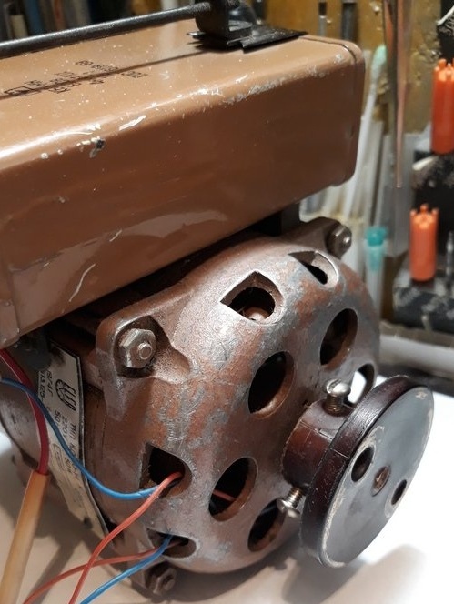
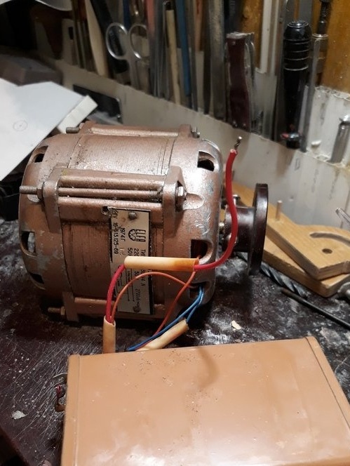
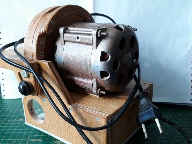
Naturally, the first thing is an electric motor. From the presence of stopped on the electric motor KD-30-U4 with a capacitor already, no need to pick up.
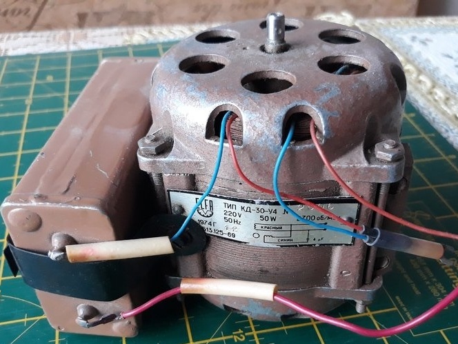

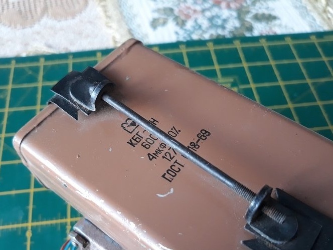

Capacitor with mount, I think come in handy for the intended.
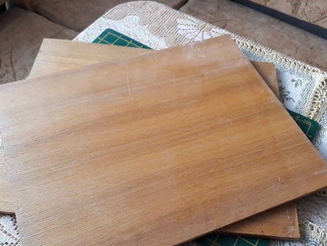
Plywood 10 mm thick is.
Found a sleeve for mounting the working disk of the machine. Longish. Cut off
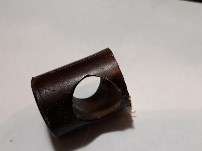
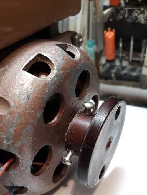
He adjusted the landing hole in the sleeve and mounted it on the engine.
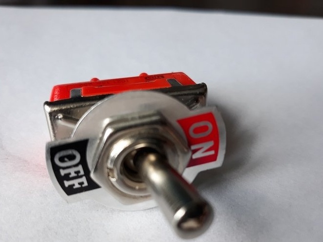
Found a toggle switch and wires.
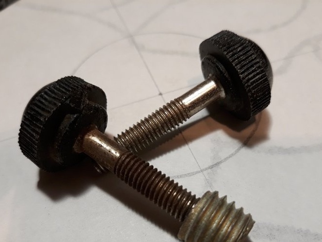
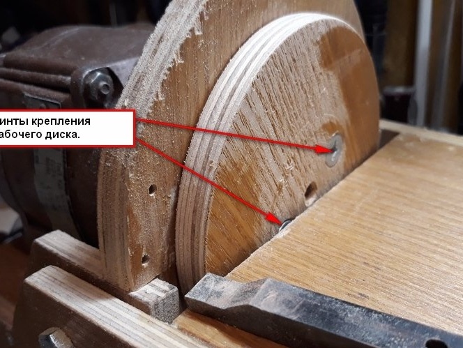
Picked up the clamping screws.
The rest I think will follow.
2 step. Parts manufacturing and assembly.
To begin with, I made a drawing of the machine. As planned with an inclined table. That question arose with a movable and rotary focus. Like here.
Decided not to do it yet. So far, to work, but it will be seen there. You can always finish it. After drawing, I drew on paper and cut out the main parts of the machine, so that it could be correctly placed on the material, so that there would be less waste.

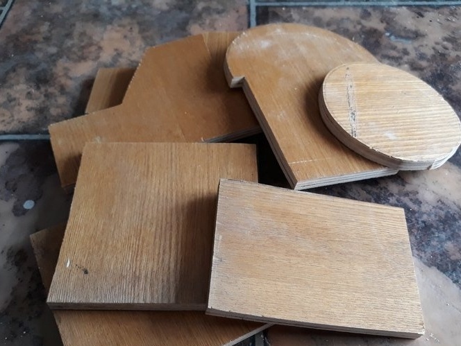
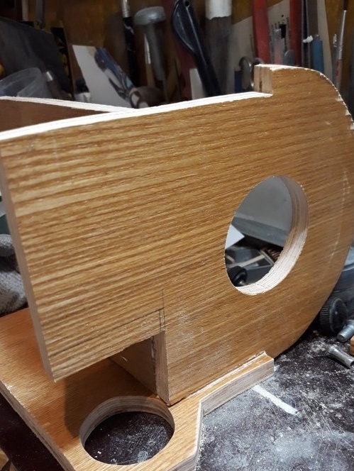
Well, then I sawed off the workpiece with an electric jigsaw.
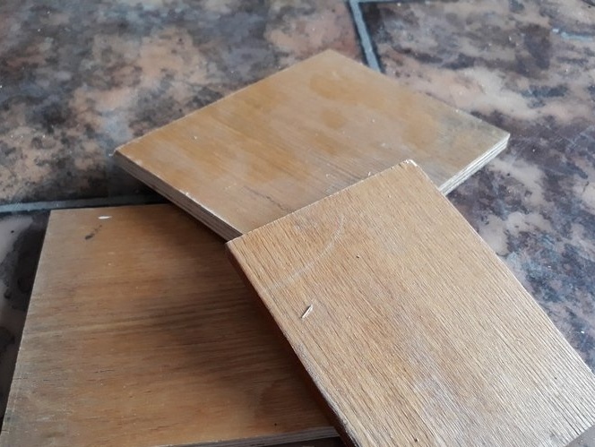
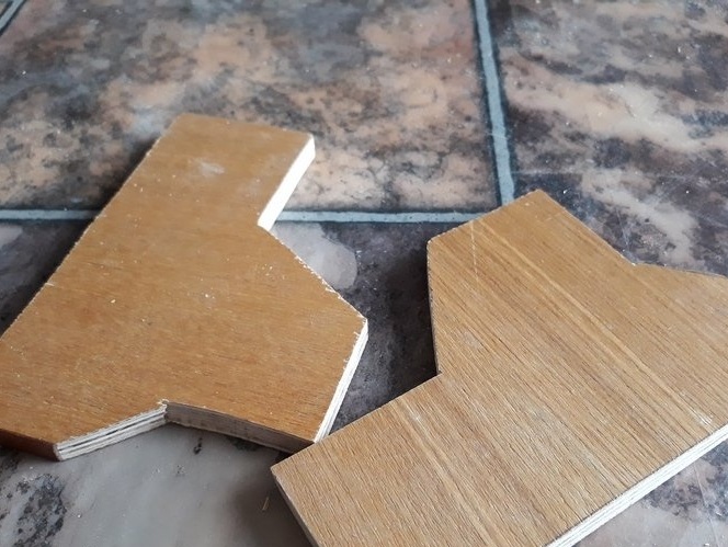
It turned out a whole bunch.
I did not trust the sides of the table with an electric jigsaw; I cut them out with a hand jigsaw.
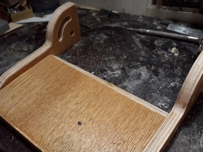
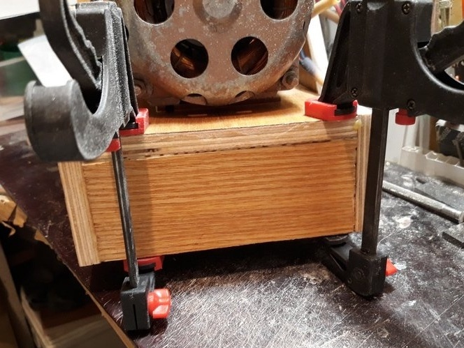
After processing the parts at the ends of the saw cuts, he began assembling. The first assembled on PVA glue moment-joiner right sidewall and engine panel.
Glued and put aside. And I think, just glue the side of the table to the countertop.
And carried away.
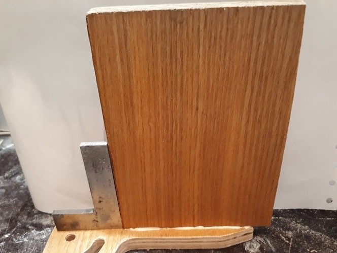
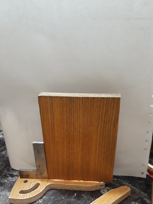
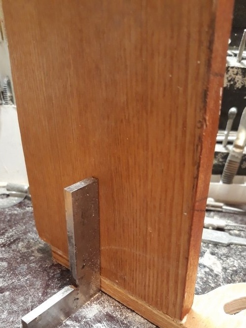
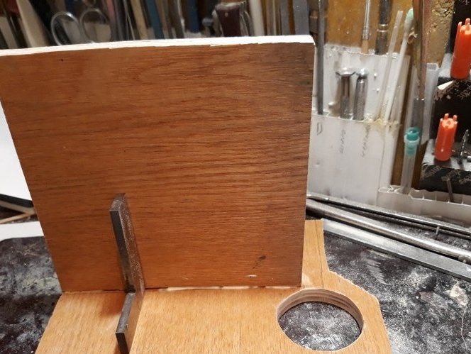
For the parallelism of the table sides and the alignment of the holes, I installed a control brass bar.
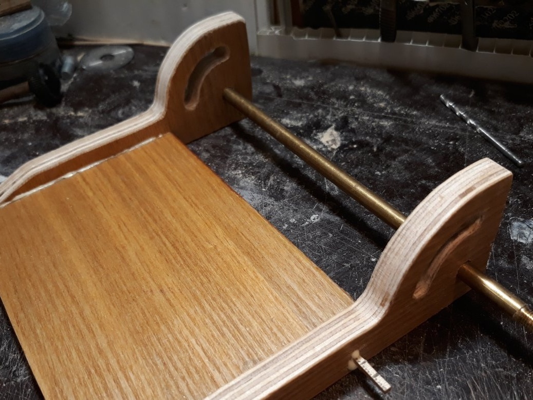
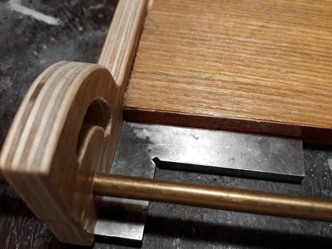
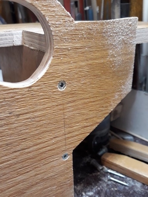
Then, after setting the glue, he drilled holes in the sides for self-tapping screws. And installed them. So the design will be more reliable.
I installed the front panel of the machine on glue.
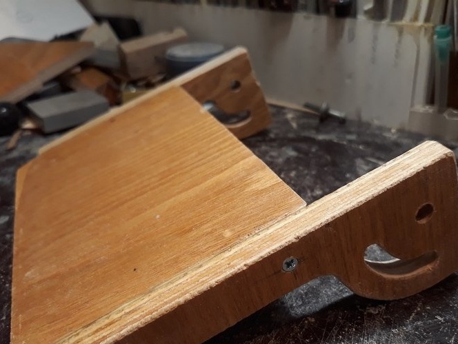
He fixed the right side of the machine, glued earlier on the screws. Also, drilling holes for screws.
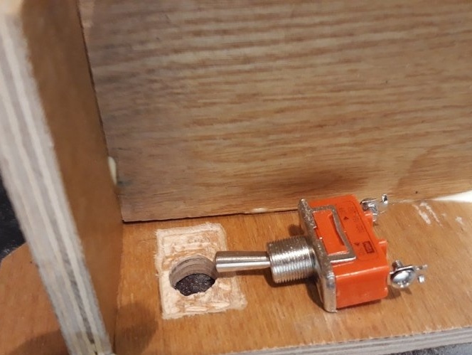
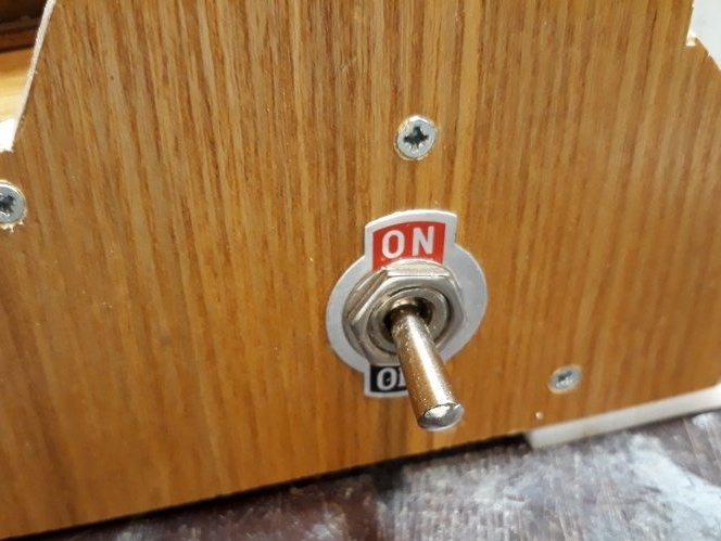
Then he put on the glue and the left side of the machine. Having previously measured, the toggle switch and having made a selection for it in the sidewall.
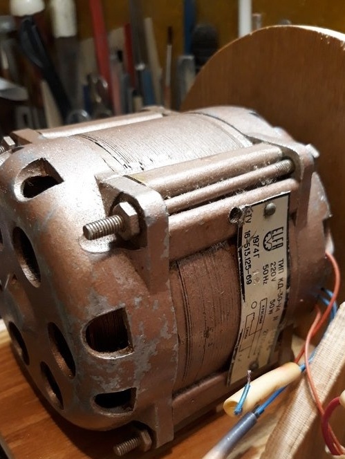
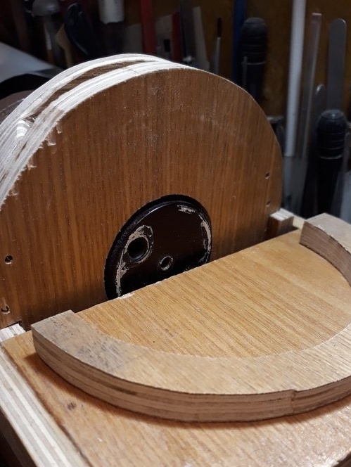
He freed the electric motor from the capacitor and its fastening.
Marked and drilled holes on the motor panel to install the motor.
He put the electric motor in place and secured it.
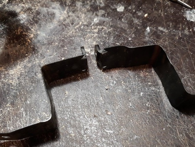
I tried on the installation of a capacitor, marked out the tapes of its fastening to the inner plane of the electric motor panel, and bent them in place.
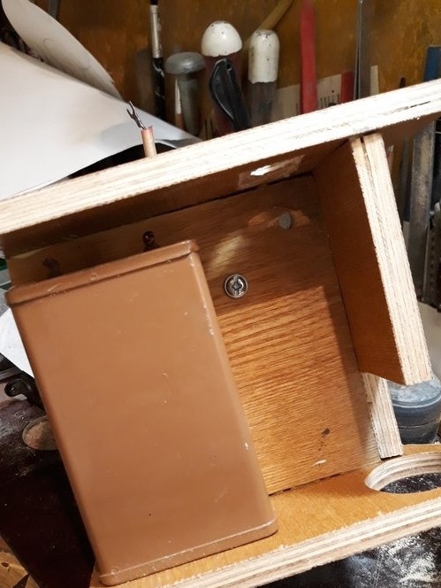
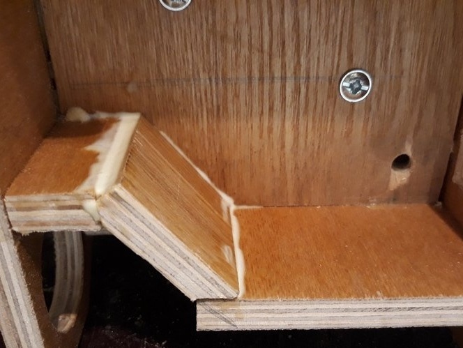
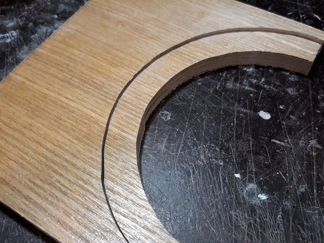
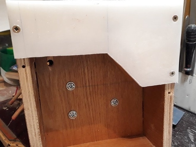
Marked, sawed and installed in place the curved wall of the chip collector chamber.
I installed the rear wall of the machine housing on the PVA glue.
I marked the bevel of the chip collection chamber on the front panel of the machine and processed it according to the marking.


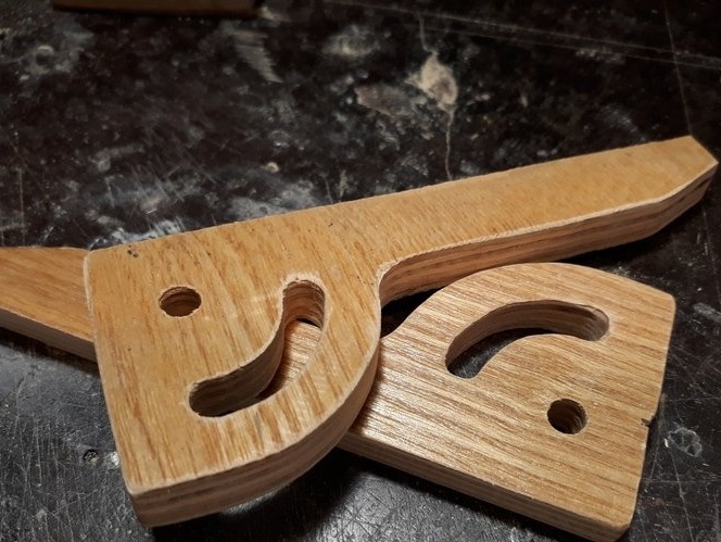
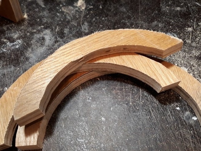
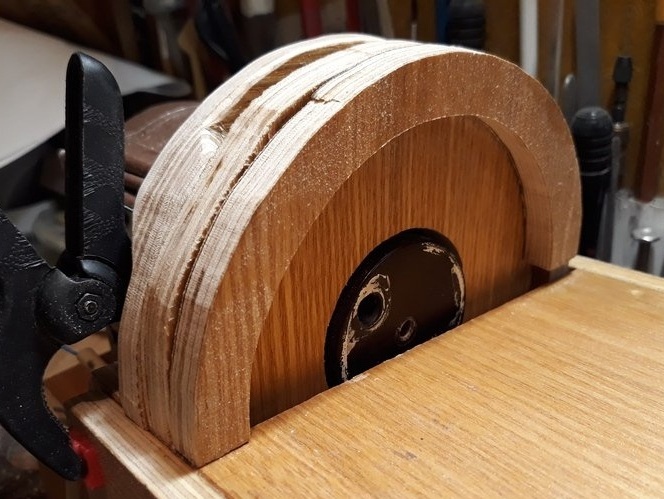
Marked and sawed a protective cover for the working disk of the machine.
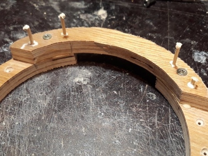
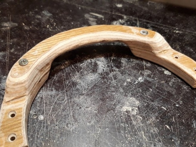
I marked and sawed the protective cover on the back of the front panel of the machine, which plays a dual role - the protective cover and handles for carrying the machine.
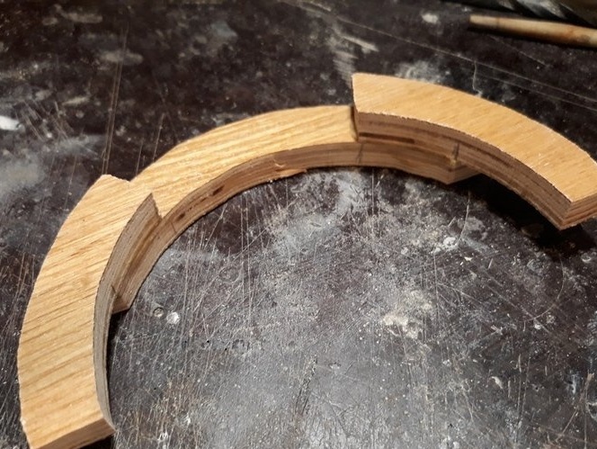
I assembled a casing-handle for PVA glue and self-tapping screws, Processed for ease of use.


It is attached to the back of the front panel of the machine, thereby removing it if necessary is provided for self-tapping screws.
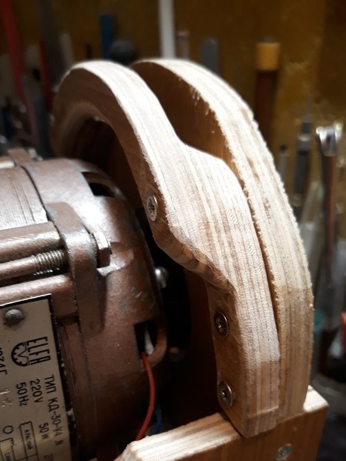
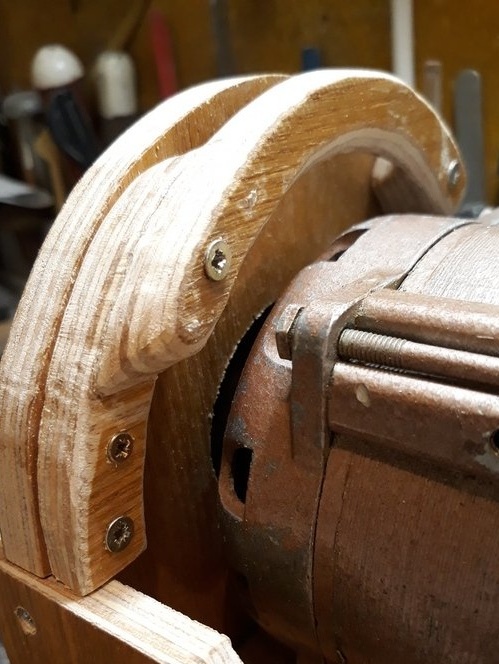
A hole is provided on the housing for adjusting or clamping the sleeve of the working disk.

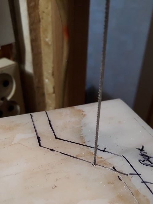
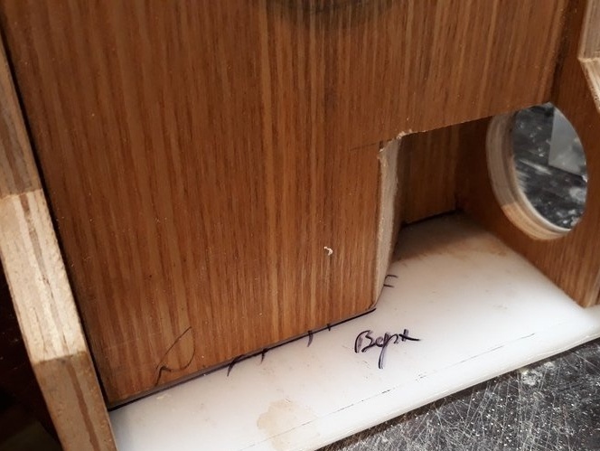
I decided to make the base of the machine from plexiglass.
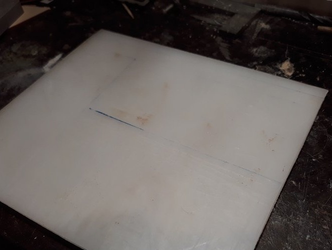
I sawed off the workpiece and tried on. Next, the workpiece was divided into two parts. The first is the base of the chip collection chamber. The second is the base, or rather the cover of the electrical compartment. He made the appropriate marking and sawed the base blank.

The lower part of the chip collection chamber was installed on self-tapping screws.
Pre-drilled the required holes. Then, glued the joints of the joints with a thermo-gun for their relative tightness.
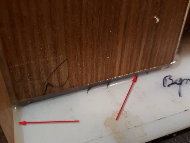
The back wall of the machine body, also glued with a thermo-gun.
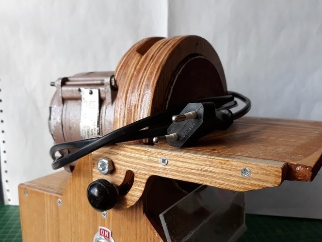
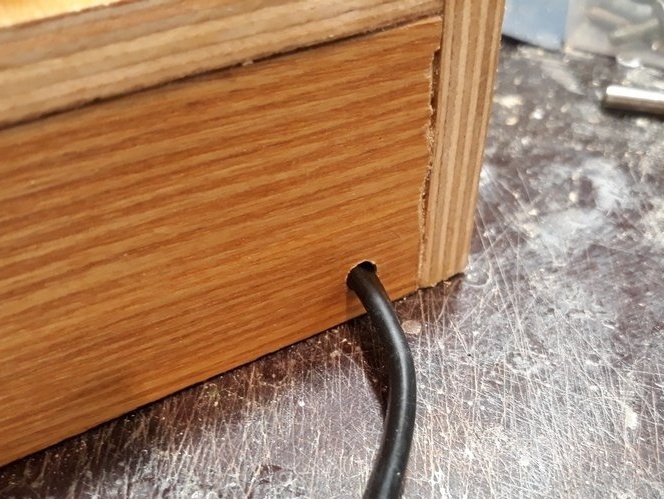
Then he began the wiring diagram of the machine. It is simple and there is no point in bringing it, put the network cable through.
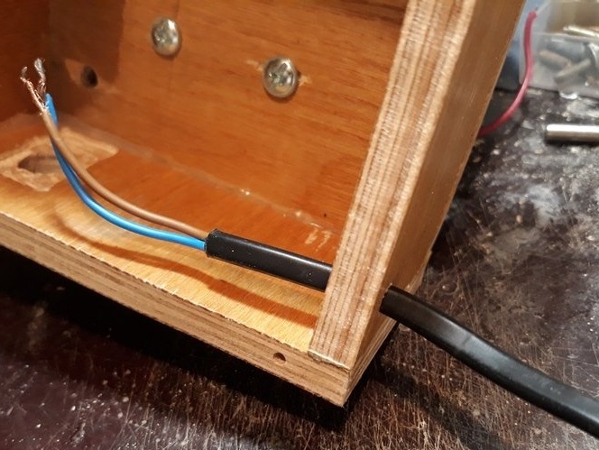
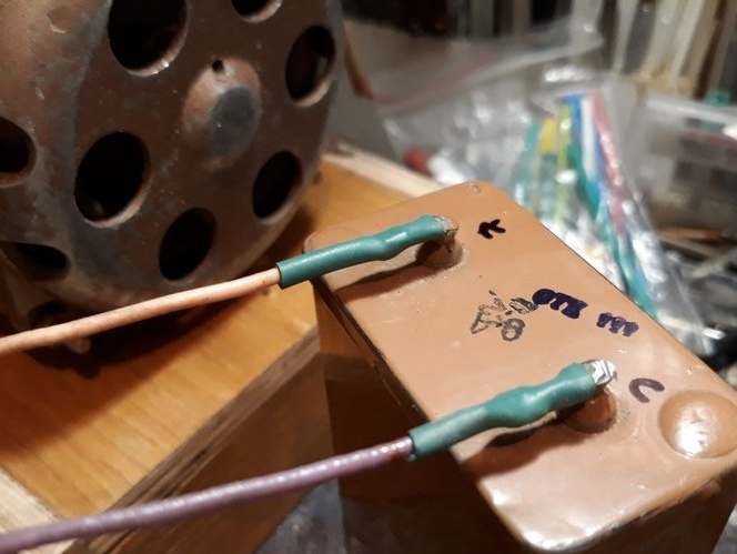
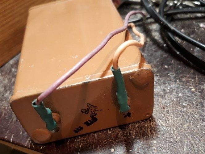
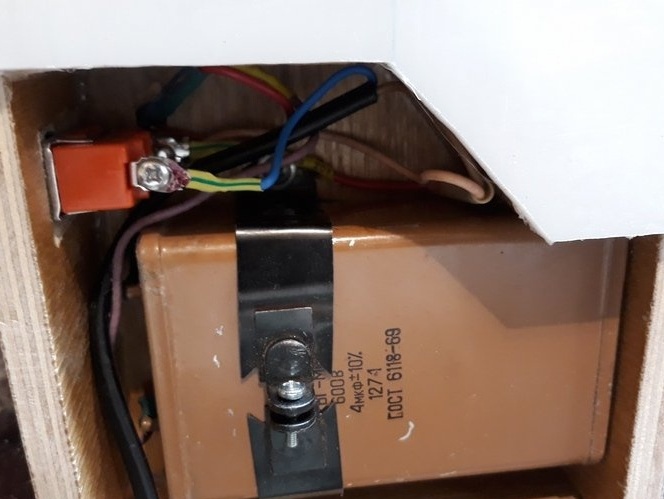
Next, I installed the clamp of the capacitor holder, laid the gasket under the capacitor
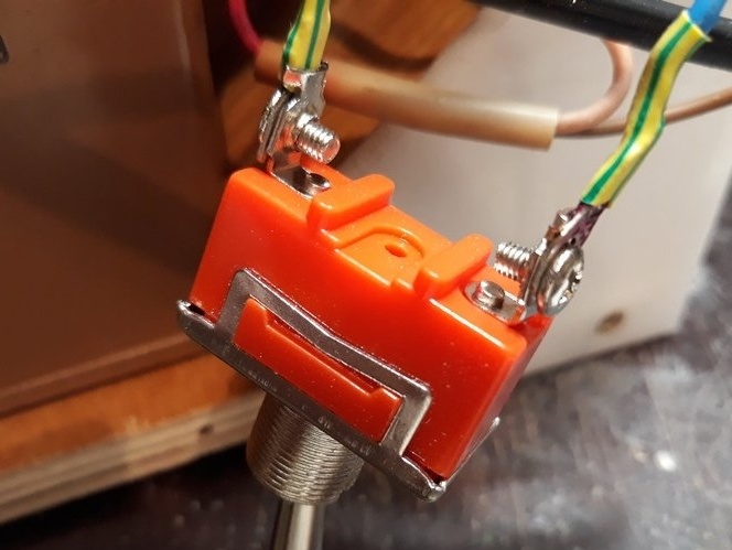
Soldered wires to the capacitor, molded them. Soldered the power switch. I installed the capacitor in place and secured it. Installed a toggle switch.

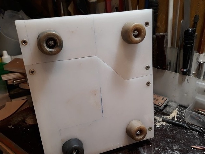
Marked the mounting holes of the machine supports. Two fell on the chip collection chamber, and two on the electric compartment. He drilled holes, strengthened the supports and closed the electric compartment.
Turned on the machine. Everything works.
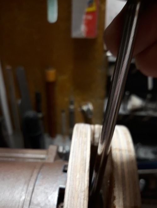
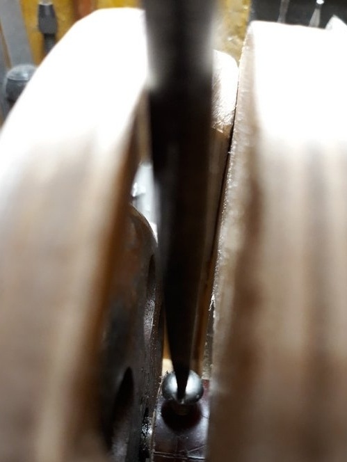
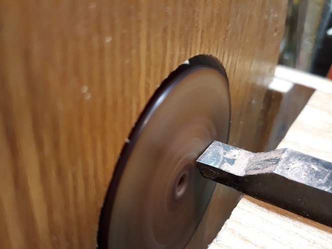
The cutter made a preliminary treatment of the mounting sleeve of the working disk of the machine.
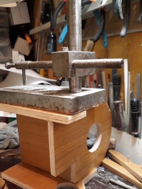
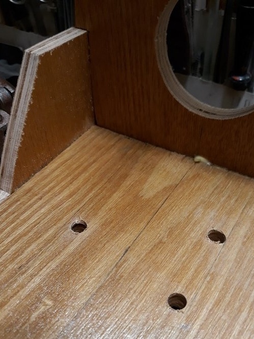
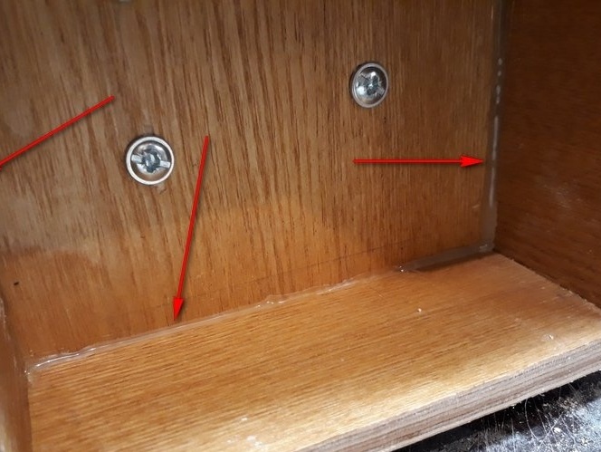
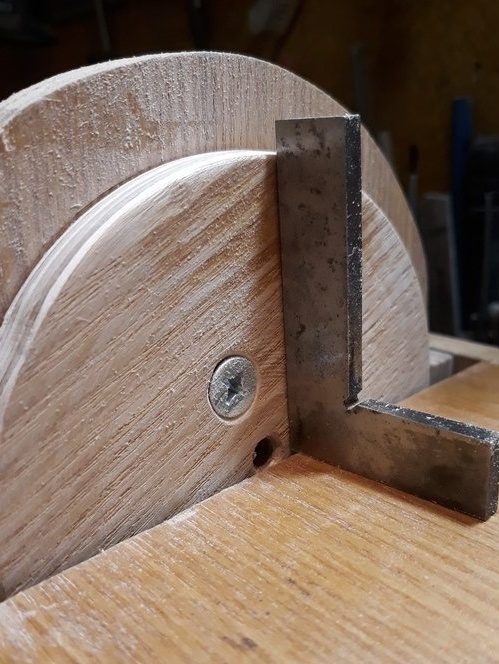
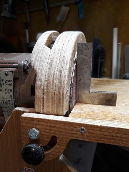
Having previously fixed the machine table, I made a marking for drilling holes to fix the table.
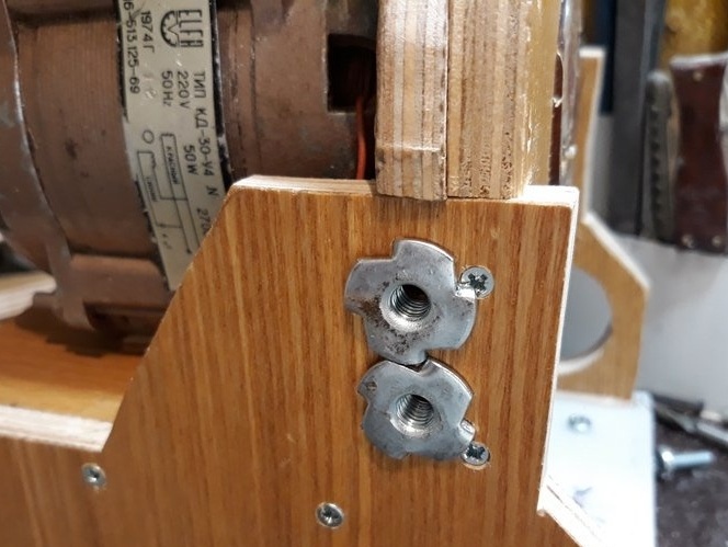
By marking, I drilled holes for installing furniture nuts on the axis of the table.
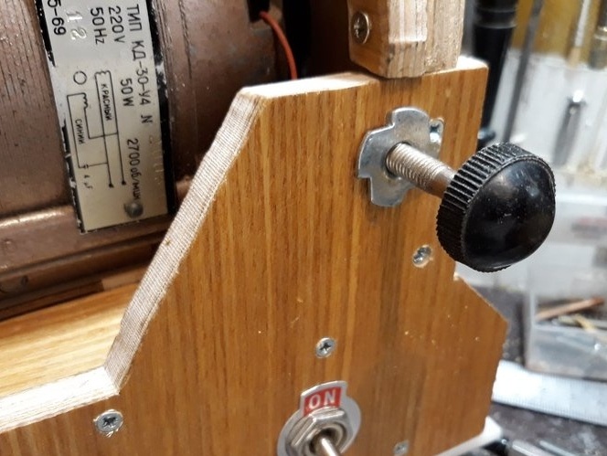

A little lower, according to the marking of the hole for furniture nuts, for the screws for clamping (fixing) the table.
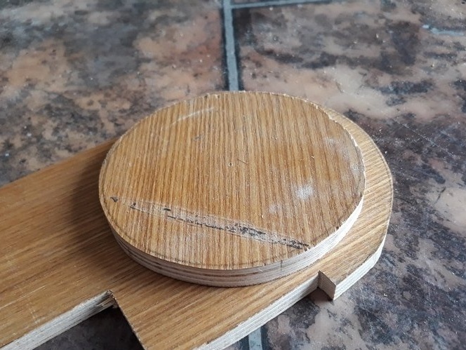
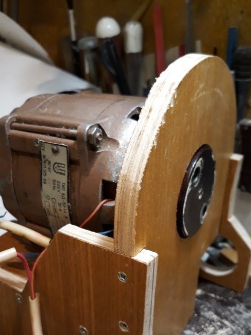
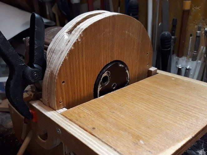
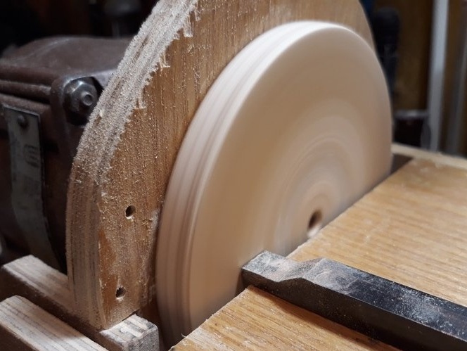
Further, I installed the working disk on the working disk bushing, having previously applied “Moment” glue to both joined parts.
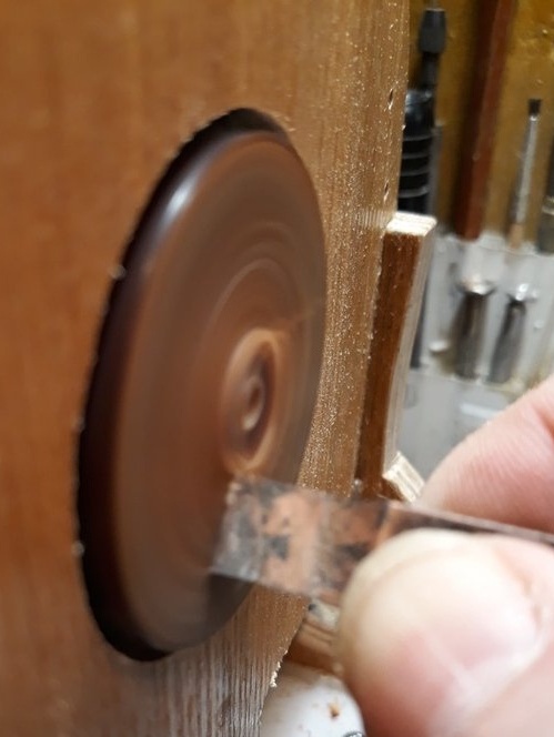
Then, he started the machine and made a frontal groove of the working disk to completely get rid of the runout of the working disk relative to the table.
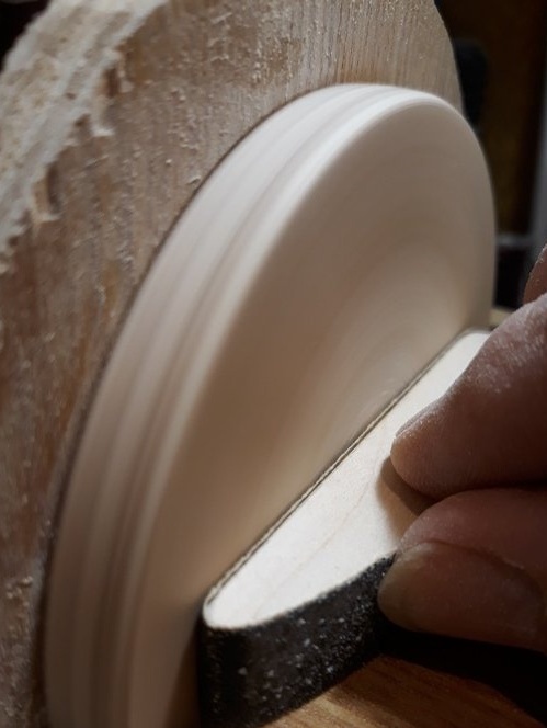
Next, pasted a double adhesive tape on the surface of the working disk.
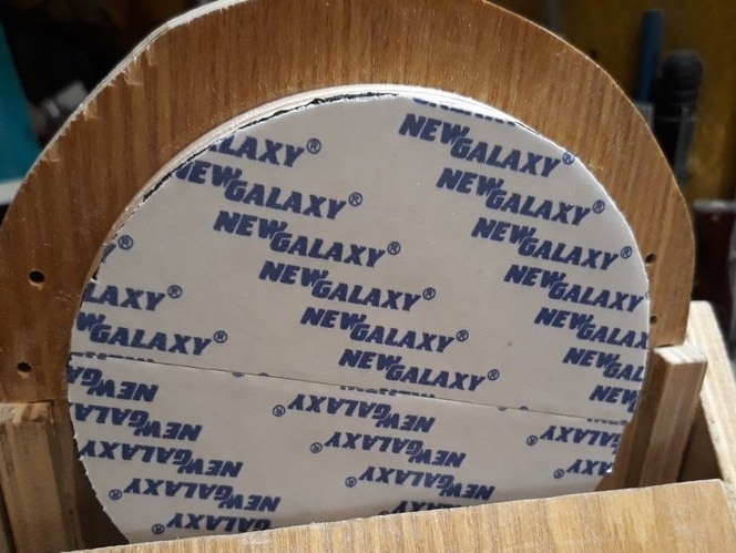
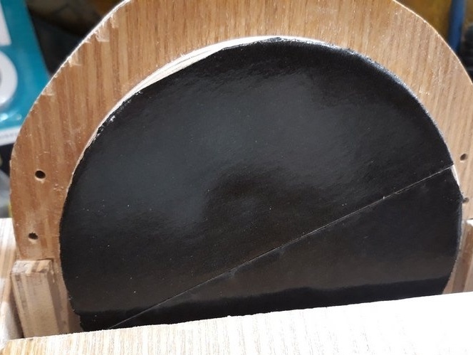
He removed the protection of the second layer of adhesive tape and glued an emery skin, then cut off the dimensions of the working disk. And installed the protective cover of the working disk.

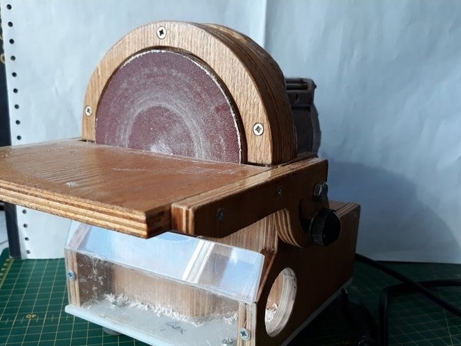
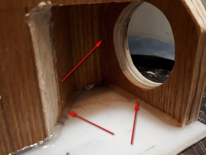
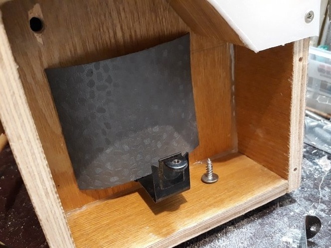
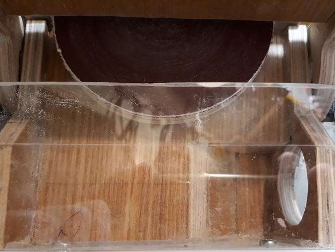
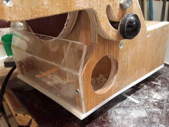
From organic glass, so that you could see the filling of the chip collection chamber, cut, bent and installed the front wall of the chamber. Mounting is carried out by self-tapping screws.
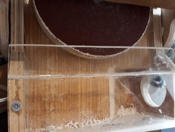
If necessary, chip removal can be carried out using a vacuum cleaner.
The hose of which can be connected to the machine through the hole in the right side of the machine.
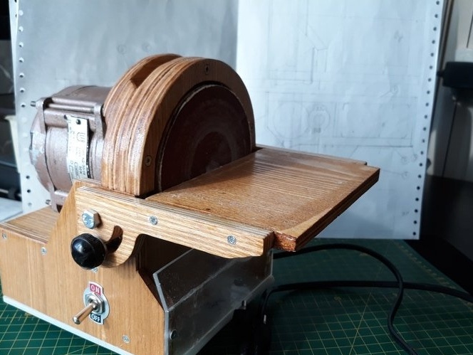
Well, that's all.
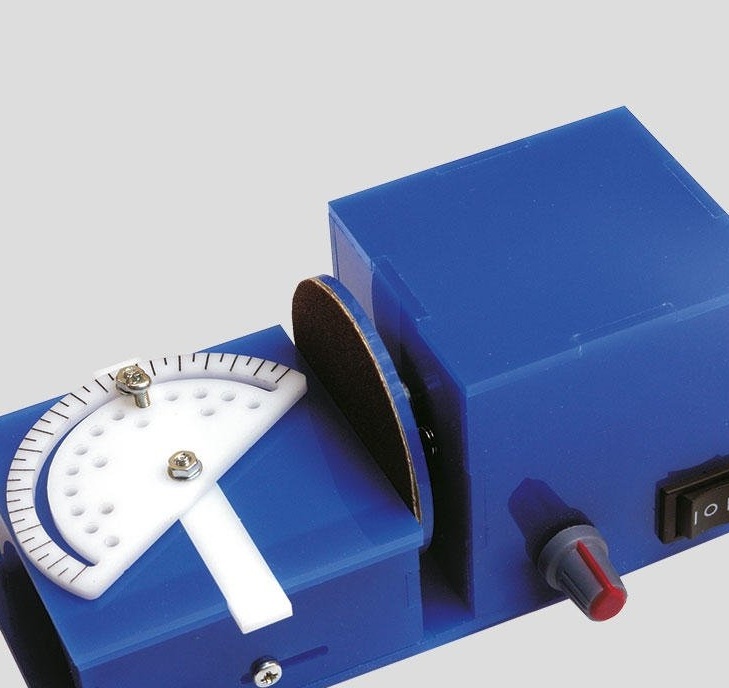
The result is such a workable machine.
Good luck to everyone and good ideas.
See, criticize, advise, ask.
Regards, Starp.