
And not only the musician, but also the singer, dancer. It is also used by the metronome in some school physical experiments in mechanics.
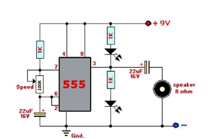
The traditional mechanical metronome in a wooden “house” housing and with a movable pendulum is good for everyone, but it was always quite expensive, and friends, as soon as this opportunity appeared, found it an inexpensive, “quick-launching” alternative in the form of a “snap” with an adjustable click frequency - first on neonka, then on two transistors. Then, after the appearance of the microcircuits, they went into the process. The metronome on the 555 chip (KR1006VI1) is especially convenient, since its click frequency depends only on the position of the handle, and not on the supply voltage.
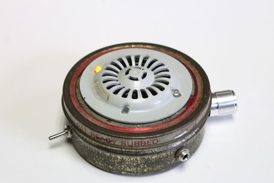
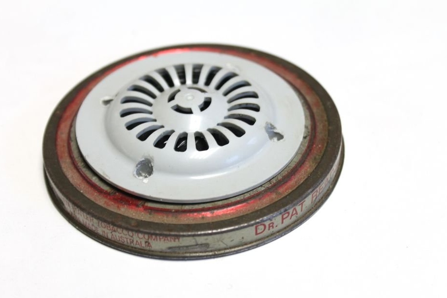
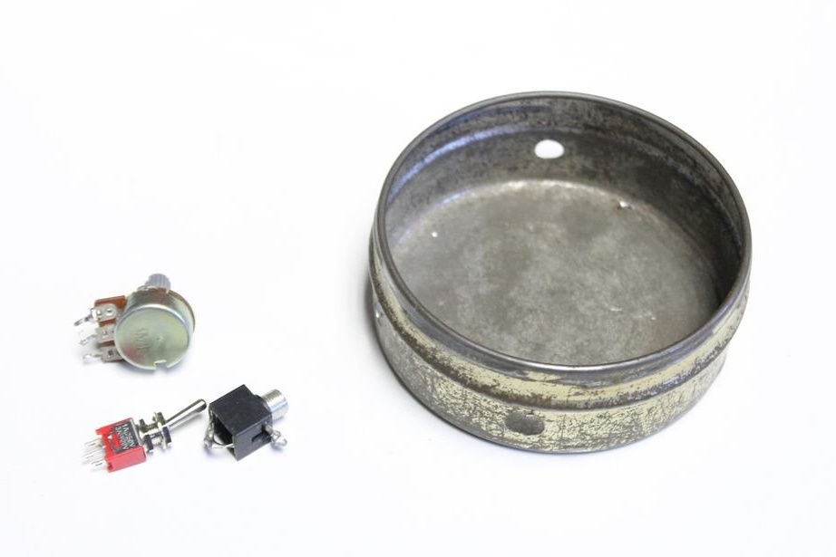
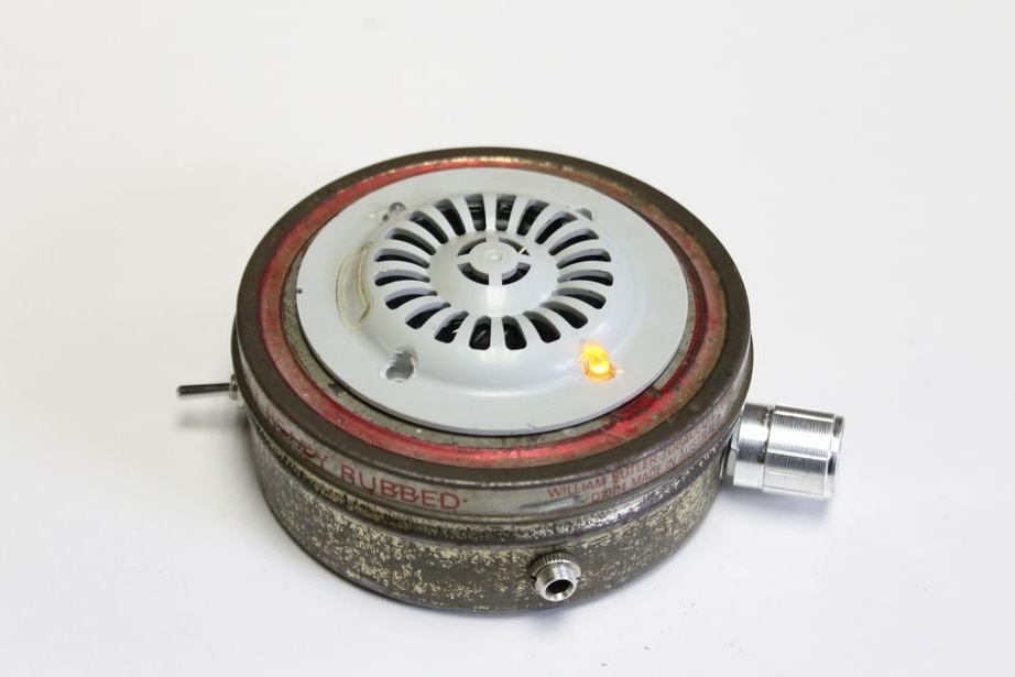
When the son of the author of Instructables under the nickname lonesoulsurfer began to learn to play ukulele, he received just such a metronome as a gift. The body of the device is a metal can of two halves, the handle of a variable resistor is also metal, and holes for two LEDs are drilled in a plastic overlay for the dynamic head. Also in the metronome provides headphone output.
The metronome is designed so that the LEDs blink: when one turns on, the second turns off, and vice versa. The dynamic head, however, clicks both during the transition from logical zero to one, and in the reverse transition:
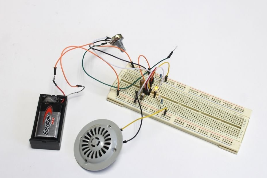
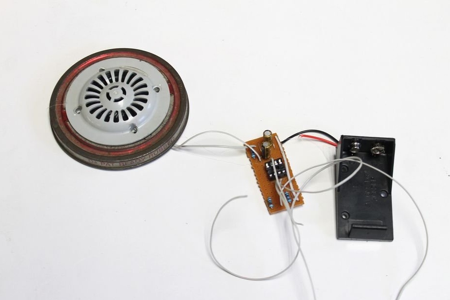
The wizard checks and debugs it on a breadboard type board:
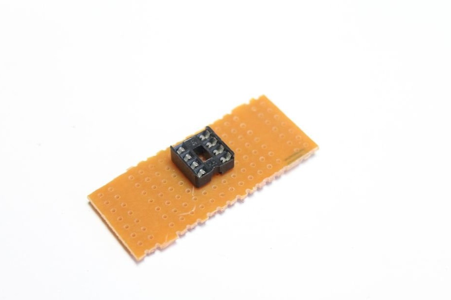
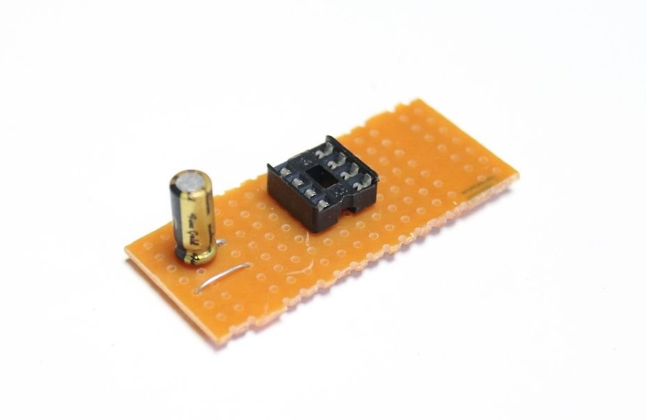
After making sure that everything works, he cuts out a small fragment from a prototype board of another type - perfboard, and begins to transfer components to it. It starts with a socket for a chip, it is optional:
Then solder the capacitor (it is polar), a jumper:
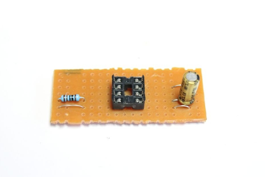
Resistor and more jumpers:
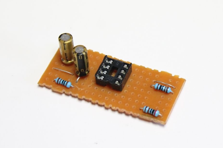
More capacitor and resistors:
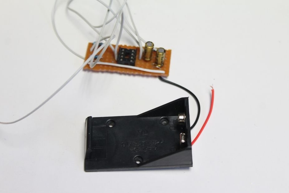
Adds conductors and battery compartment (polarity is important here again):
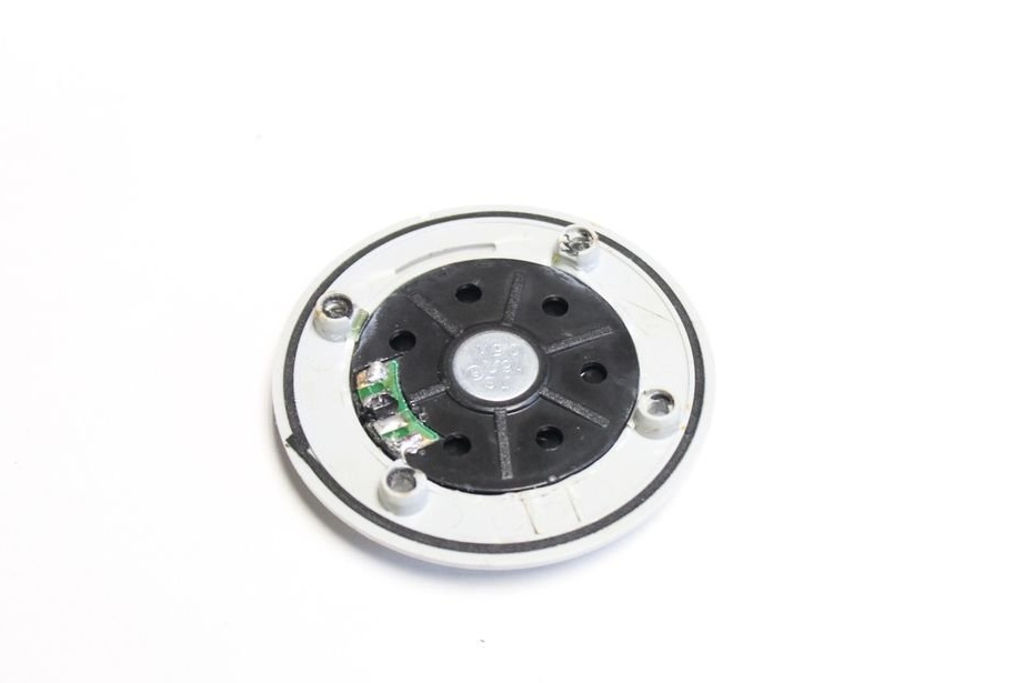
Drills fastening holes for a dynamic head with an overlay in the upper housing cover:

But with what they should coincide:
Installs:
Connects:
Adds a switch, a variable resistor, a headphone jack:
The LEDs are placed directly in the mounting holes of the lining on the dynamic head:
So it looks from the front:
It completes the assembly of the circuit, when soldering LEDs, it is also important to observe the polarity, and the microcircuit should be positioned correctly in the socket:
Sets the handle on the axis of the variable resistor:
The metronome is ready. Build process on video: