


The master invented Kravox during a research project at Lund University (Sweden), whose goal was to give digital musical instrument controllers the feel of traditional mechanical instruments. Now the master wants to make Kravox accessible to everyone as a music platform for experimentation. It was for this that he created this detailed briefing, which will allow as many people as possible to use this new interesting musical instrument.
Playing Kravox is pretty simple. Imagine that you are playing with an ordinary object, such as a broom, and the way you touch it and move it in space controls how the sound is generated. You can watch and hear how to play Kravox, as well as the process of making the instrument, at the end of the article in the videos.
Tools and materials:
- breadboard 50 * 24 holes -1 pcs;
-40-pin male connectors -5 pcs;
-40-pin plug - 5 pcs;
- Potentiometers 10 kOhm and handles for them - 5 pcs;
-Blue 5 mm standard LEDs - 3 pcs;
- Resistors 150 Ohms - 3 pcs;
- Capacitor 10 uF - 2 pcs;
- Capacitor 100 nF - 2 pcs;
-Radio module NRF24L01 - 2 pcs;
-Arduino nano -2 pcs;
-Resistors 220 Ohm -3 pcs;
- Boards of sensor sensors MPR121 - 2 pcs;
- Digital gyro GY-521 MPU 6050 - 1 pc;
- USB-A to USB-C cables;
-4 meters (minimum) of copper tape 1 cm wide;
-Powerbank;
-7 meters (minimum) wires of different colors;
-0.2 meters, heat shrink tube ø = 3 mm;
-Soldering accessories;
-Multimeter;
-Rule;
-Knife;
-Hacksaw;
-Pliers;
-Cardboard;
-Glue gun;
-Scotch;
-Glue;
-Office gum;
-Clips;


Step One: Theory
Kravox is an open source cross-platform digital musical instrument that consists of three components - a controller / controllers, a receiver, and software.
You can connect up to three wireless controllers. Each controller processes orientation and acceleration data from the MPU-6050 digital gyroscope and touch data from two MPR121 sensor sensor boards connected to the Arduino Nano. The controller sends data to the receiver using the nRF24L01 radio transmitter. If it is necessary to use more than one controller, the second and third controller must be assigned individual addresses.
The receiver transmits data received from the controller (s) to the connected computer along with data collected from several potentiometers.The provided receiver code allows you to establish communication with three controllers, but it will also work with only one or two without settings.
Data from the receiver is processed in a program written in that outputs sound.
The beauty of Kravox is that its form, how it sounds and how to play it, can be adjusted. This gave the wizard the opportunity to develop an easy-to-copy version of Kravox for this lesson.


Step two: create a controller board
Next, the wizard explains how to do electronics controller step by step from the above details.
If you are uncertain where to solder the cable, you can always return to the circuit diagram and check whether the components are connected correctly.


The first step is to cut the breadboard and connectors and assemble them together with a small and a large capacitor, which help increase the reliability of the radio transmitter.
Cut the board with a utility knife
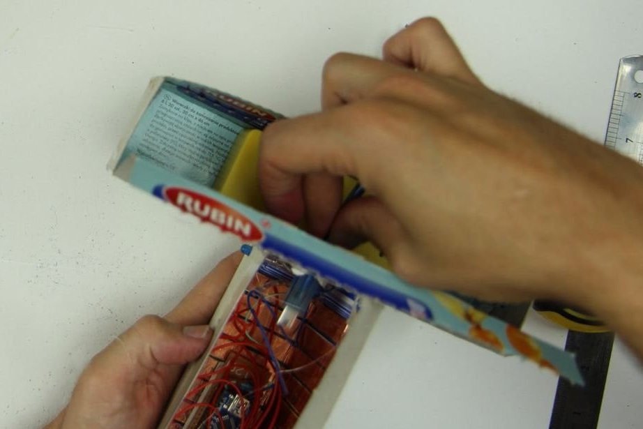
Cut the connectors with a hacksaw (the master put them on the book to align them from the table)
Install the connectors on the breadboard and solder. You can already connect each pair of contacts of two
long connectors that are adjacent to each other. For the rest, it is enough to simply attach them with a small solder - preferably contacts that, in accordance with the circuit diagram, will not be connected later. When soldering capacitors, pay attention to the polarity of the electrolytic capacitor of 10 microfarads (the larger of the two). One side will have a strip and, as a rule, a shorter leg. This side must be connected to the ground. The smaller 100 nanofarad capacitor is not polarized and can be soldered in any way.


Further, the LED resistors are soldered. Pay attention to the polarity of the LED: one side usually has a shorter leg. This side should be connected to the ground in the next step. A blue wire is soldered to the other leg. The other end of the wire is soldered to the connector where the Arduino pin D3 will be connected.


Next, all red and blue power cables are mounted. Red for 3.3 Volts and blue for ground (GND).


Three sensor boards communicate via I2C protocol (integrated circuit). This means that they can all be connected to the same two Arduino pins, so we solder the yellow and green wires to the sensors and Arduino A4 and A5 pins. You also need to mount a white cable to connect the interrupt contacts of the gyro.


The radio transmitter communicates via the SPI protocol (serial
peripheral interface), which requires more connections than I2C, the wizard adds black, gray, brown, purple and orange wires.


Now it's time to prepare the components. In addition to soldering on pin connectors, if not
soldered, you need to pay special attention to the sensor board! For cheap models from China, the address pin is rigidly grounded without an intermediate resistor, so it is necessary to physically cut this connection at the bottom of the board with a knife. Cut between two pads near the place where ADD is written. The wizard recommends ringing with a multimeter to make sure that the contacts are not connected.


When all the parts have soldered connectors and the sensor boards are prepared, you can connect the Arduino Nano, a gyroscope, two sensor boards, and a radio module to the controller board.


Step Three: Download Code
After a double check, if everything is connected correctly, the next step is to download the Arduino nano provided, but before you can do this, you will need to install the libraries for the gyroscope, sensor sensor boards, and radio transmitter. If you are new to Arduino libraries, learn how to install them.
The MPU6050 gyro requires the I2Cdev.h and MPU6050_6Axis_MotionApps20.h libraries, which can be downloaded.
For MPR121 touch boards, the Bare Conductive library MPR121.h is required, which can be found There are at least two versions of the library. Be sure to install the version developed by Bare Conductive, not the version developed by Adafruit.
The NRF24L01 radio transmitter board requires the nRF24L01.h and RF24.h TMRh20 libraries, which can be downloaded. Please note: there are also at least two versions of these libraries with the same name. Be sure to install the developed TMRh20, not the maniacbug.
Once the libraries are installed, you can download the Kravox-Controller code.
In order to check if the controller is working, you can enable it to output data from touch sensors and a gyroscope through a serial monitor. To do this, you need to edit the last section of the recipient code before downloading: by removing the comment mark at the beginning (/ *) and at the end (* /) of it (see. Photo)
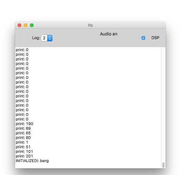
After downloading the code with this option, you need to open the Serial Monitor and set the transmission speed (data rate) for it to 115200. Now you can see the data from the sensors, which change when the controller board is moved and the contacts are touched, from MPR121 boards that are marked from 0 to eleven.
If nothing works or only zeros are obtained, you need to carefully check the wiring and compare it with the above diagram. If you receive the wrong signal from the Serial Monitor, you need to check whether the data transfer rates are set correctly.


Step Four: Board Power

For power, you need to connect the controller board to the bank.
If the bank does not turn off automatically after a while, the controller board is finished and you can go to the receiver board. Otherwise, follow the next step.
Step Five: Solve the Power Problem
In principle, the controller board is ready, but some banks will automatically turn off after a few seconds when connected to the controller board, because it consumes little power. As a solution, you can simply add three 220 Ohm resistors in parallel between the 5V and GND pins of the Arduino.


After reconnecting the components, (definitely) the finished controller board looks like this.


Step Six: Create a Receiver Board
In this step, the wizard will show you how to make the receiver board. The process is very similar to making a controller board.


First you need to trim the breadboard and connectors. Then install the capacitors. You can compare this step with the first step of creating a controller board for more information.


Next you need to add all the red and blue wires. Red for 3.3 Volts and blue for ground (GND).


Wiring for communication SPI.


The receiver board is ready, but before you upload the Kravox-Receiver code to the Arduino Nano, you must first create an interface for the receiver.


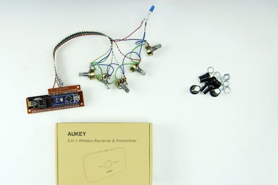
Then the wizard shows how to make an interface with 4 potentiometers and an LED for the receiver. The interface is connected, as in the first figure, and will be connected to the receiver board, as seen in the second figure.


The procedure is as follows, first you need to take a bundle of 8 cables and solder 5 of them to the middle contacts of the potentiometers. It is advisable to use the same colors as in the diagram so as not to get confused.

Then, you need to cut the breadboard 2 rows of 17 holes and a 17-pin male connector. Attach the cables and connector to the board. Pay attention to the diagram above to make sure that you connect the cables in the right places.


Now you need to solder blue wires (ground) to one of the contacts of all potentiometers. Solder a blue LED with a current limiting resistor of 150 Ohms.

Solder green wires.

The finished interface should look something like this (photo 1) and can be connected to the receiver board like this (photo 2).
Seventh step: code
Now available for download to Arduino Nano receiver.
To check, you need to make a small adjustment to the code again before downloading. By default, the receiver displays its data in a format that can be interpreted as pure data, but does not display useful information on a serial monitor. However, you can change this behavior in your code by editing (adding // before) the line #define WRITE_AS_BYTES and (removing // before) the line // #define PRINT_VIA_SERIAL_MONITOR.

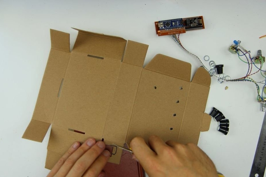
Step Eight: Case
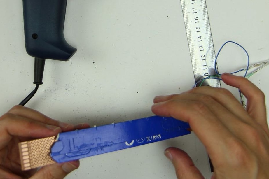
Further out of the copper strip, the master makes a sensor.


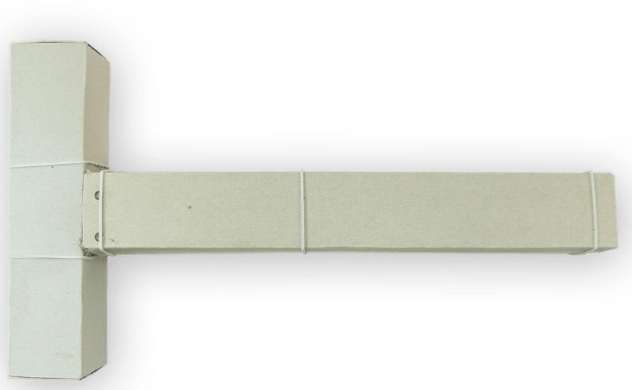
To make the case, the master uses empty boxes.

The master draws cardboard. Cuts 24 copper strips and fastens on a cardboard.


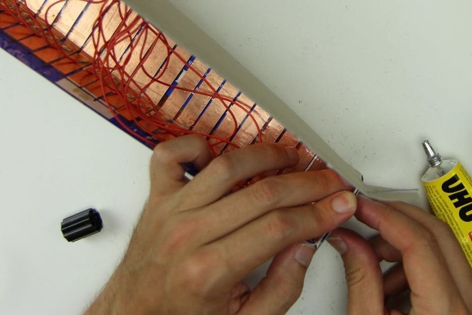
Further, the master cuts cardboard 2 * 24 holes wide and the 24-pin male connector to size and solders 24 wires to it. The wires in the middle should be at least 10 cm long. As you move away from the center, the length of the wires increases. For example, if you use a copper tape 1 cm wide and the distance between the electrodes 3 mm, the length of the wire should increase by 1.3 cm, as shown below: 10 / 11.3 / 12.6 / 13.9 / 15.2 ...
Now you can solder the second ends of the wires to the copper strips and seal the strips with tape.


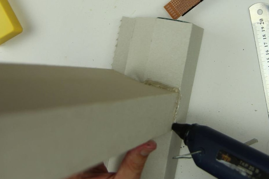
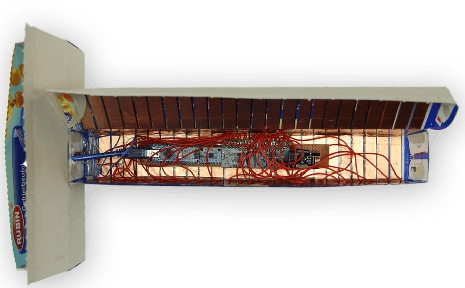
Glues the sensor into the body, and then glues another body to it (for verification).
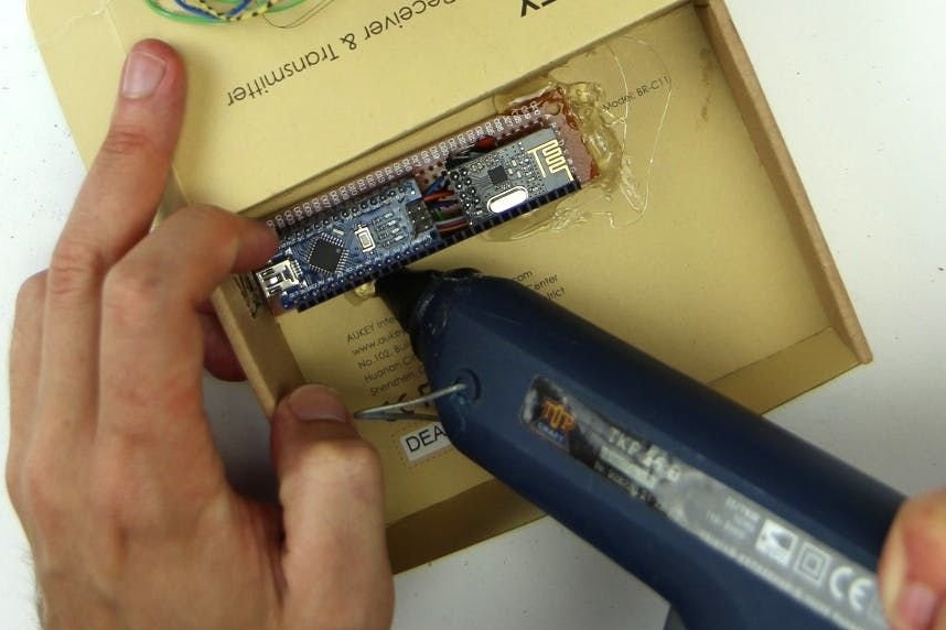
Covers the back of the controller board with cardboard.
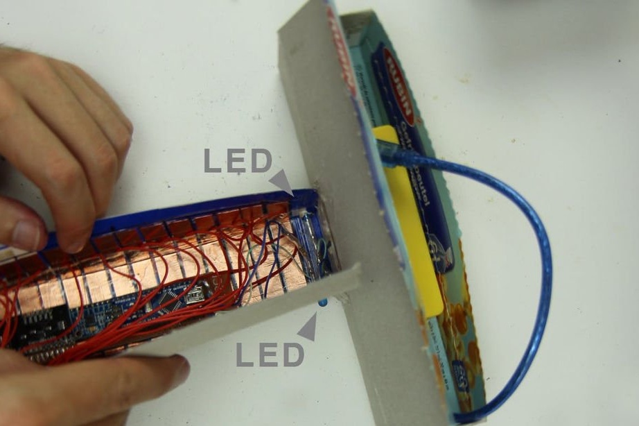
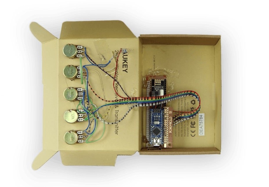
Installs LEDs and power bank. You need to arrange the power bank so that you can connect and disconnect the USB cable, because this is how the controller turns on and off. Also connect the touch interface to the controller board and put it in the box.
Makes a cutout for the USB-A-USB-C cable at the junction of the two boxes, holds it out and connect it to the Arduino Nano.
Now the controller is ready.
The master fixes the case with the help of stationery gum. If subsequently problems arise with sensors that detect touch when they are not present, you need to put insulating material, such as film, or the like between the touch-sensitive housing, the circuit board, and the wires. Connect the power without touching the sensors.
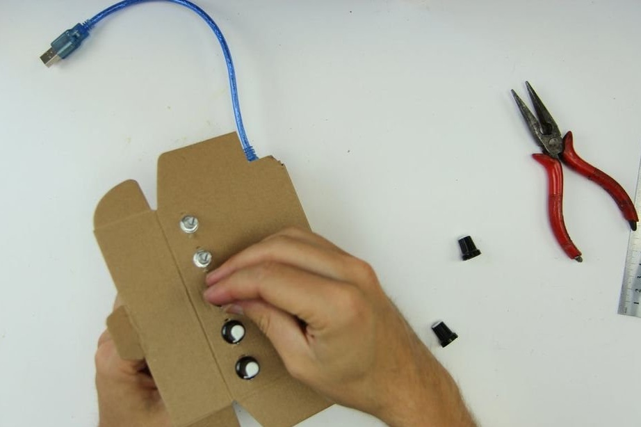
Step Nine: Creating a Receiver Case
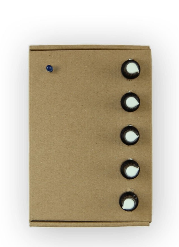
Now you need to make a housing for the receiver. The wizard cuts several round holes for potentiometers and LEDs.
It glues the receiver board, LED, screw potentiometers. Sets the handles.
Step Ten: Complete
Now that all the equipment is mounted, it's time to play music! To do this, you need software that you can connect equipment to. For Kravox, this is Pure Data Vanilla software, which you can download for free.
After installing Pure Data on the computer, you need to run it and open the Kravox.pd file. Please note that it must be saved on your computer in the same folder as the drumsamples folder with which it is supplied - otherwise Pure Data will not be able to find the files.
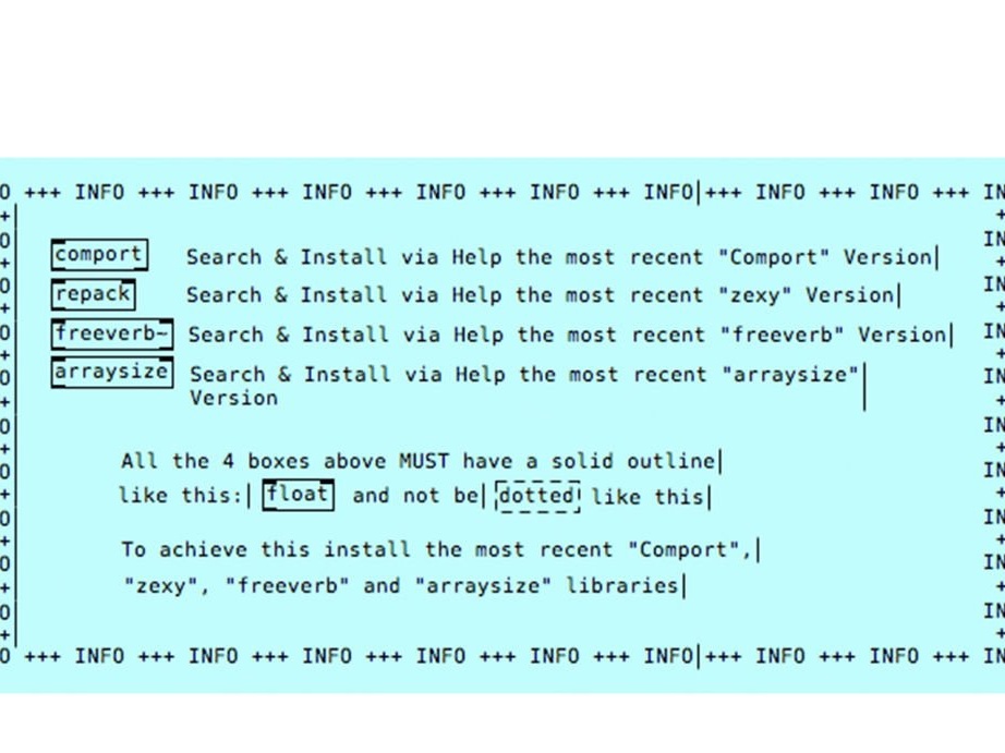
As soon as the Kravox.pd program interface opens, you need to open the window as in the photo and install the four so-called external devices that are listed in this window. Installing them is simple, just click "help" in the "Clean Data" menu, select "Find additional objects on the internet" (it may be slightly different), find "comport", "zexy", "freeverb" and "arraysize". "one by one and install the latest version. Now the four objects marked as comport, repack, freeverb and arraysize should have a solid outline, as in the figure below. You may need to restart Pure Data for this.
After installing external devices, you can connect the receiver via USB. If you changed the code in Part 4 to use the Receiver with the Arduino Serial Monitor, you must first undo this change and load the source code into the Arduino Nano receiver before connecting and closing the Arduino Serial Monitor.
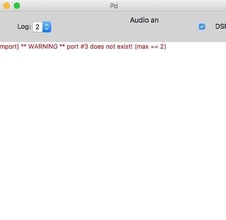
Now take a look at the Pure Data window. If you see a rapidly updated data stream, this is great, but most likely it will show you a red message instead, like the one in the first image, which is updated every two seconds.
The red text may be a little different, but still it means that, Pure Data has not yet been able to connect to your receiver. This is because the program needs to specify which USB port to connect. USB ports can be labeled differently on different devices; on the 2014 MacBook Pro, Pure Data recognizes both USB ports as serial port 3, regardless of which receiver you are connecting to. Then the wizard used Kravox with the Lenovo Yoga Pad with only one working USB port, which was designated as serial port 6. On Windows, the ports are designated as 8 and 9. The wizard advises just to try to find out which number the USB port works on your device . He created a dialogue as part of the Kravox.pd interface (second photo), where you can simply click on the numbers until the device works. You can also try “Show available ports” and the “Show connected USB devices” buttons.
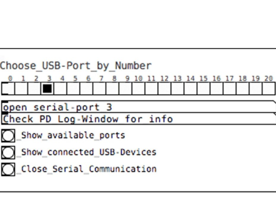
Then you need to click "Save" so that Pure Data will try to connect to this port the next time automatically.
If the controller code was edited, then you need to reload the code.
It remains to connect the controller board to the power supply. When you do this, the touch interface enclosure around the board should be closed, and the touch part of the enclosure should not touch your hands or anything else.
Everything is ready, additional information can be viewed on the video.