I decided to redo my laboratory power supply. Well, as a laboratory, rather, an adjustable power supply. I have already assembled a similar one, but for some reasons I dismantled it.
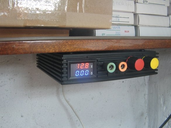
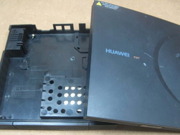
I decided to collect an unusual and not taking up much space power supply. It is unusual in that it will be suspended under a hinged shelf. I chose the box from the old Huawei modem with the case.
Accessories:
- housing from the modem;
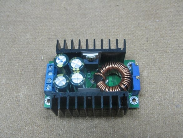
- lowering module;
- adjustment module;
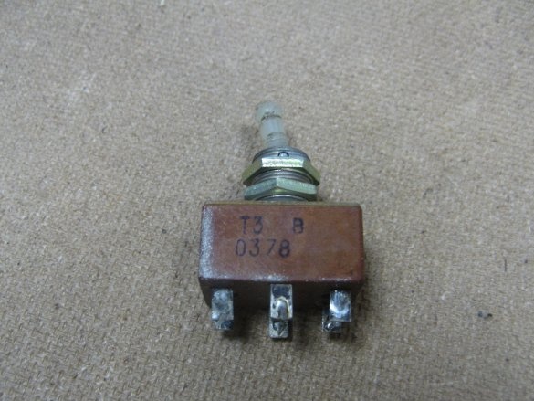
- toggle switch;
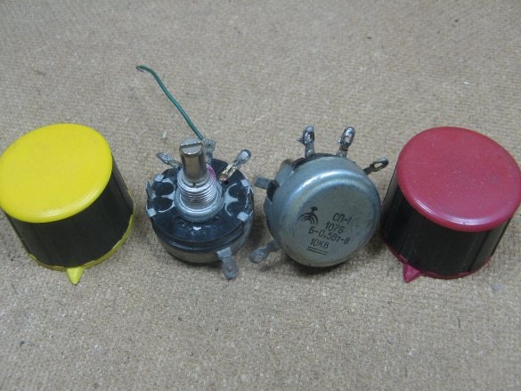
- adjustment resistors;
- handles on resistors;
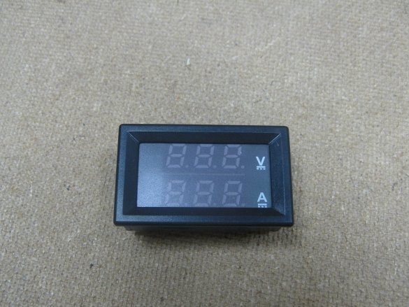
- voltammeter;
- terminals;
- instruments.
About accessories.
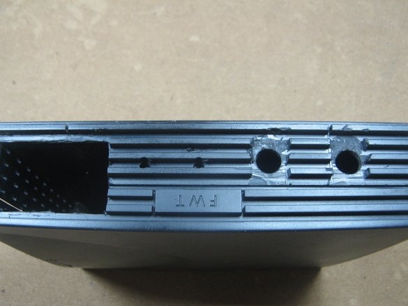
I have a case box from an obsolete and tattered modem. It is quite compact. There are vents. There is a very convenient niche for the toggle switch.
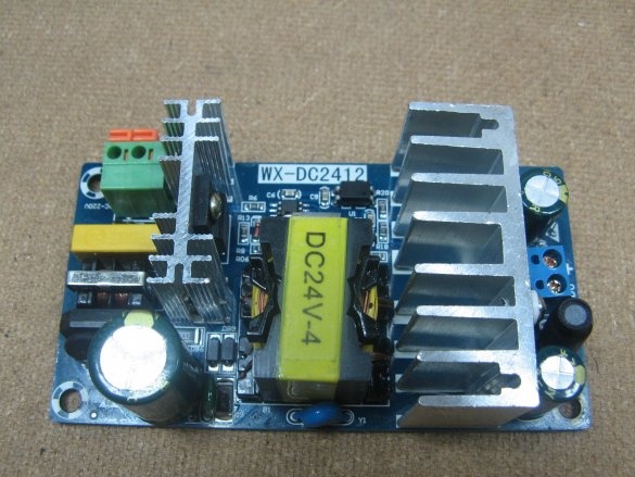
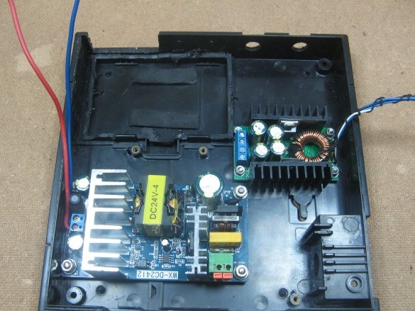
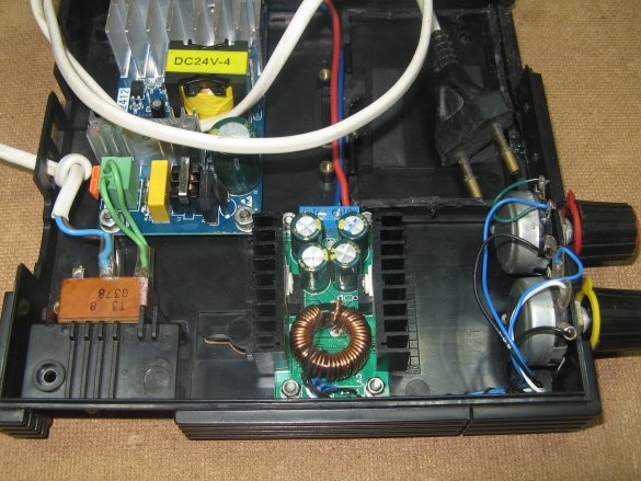
Lowering board from China. It is compact, just under my body. I squeezed more than 5A from her. Apparently this is its limit value, the nominal is kind of like 4A. The output voltage is 24V, my version produces 23.8V.
Adjustable module made in China. My version adjusts from 1.26 volts. There are refinement options on the Internet that allow you to adjust from zero. I don’t really need this, it will suit such a minimum voltage. Maximum output voltage, almost repeats the input voltage.
I will switch the mains voltage with the T3 toggle switch. I tumbled the tumblers.
Trimmer resistors of the adjustment module, replace, adjusting.
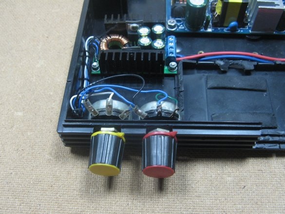
Both at 10 kOhm. Resistor handles are also needed. Initially, I took large ones, but they do not fit on the case, replacing a smaller one.
Voltammeter from the Middle Kingdom. The accuracy is pretty good, as a last resort there are tuning resistors on the back side.
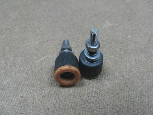
Terminals from the old measuring device, I do not remember the exact model. They are quite strong and just found a different color.
Assembly.
On the front panel we make markings for: a multimeter, terminals and resistors. Everything is very simply cut and drilled. I began to cut with a drill, but the plastic melted, even at low speed. Dorezal clerical knife.
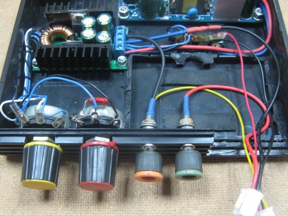
I wonder where the modules will be. I mark the holes, drill and screw the boards. Adjusting resistors soldered and soldered wires. The voltage of a pair of wires, the current three wires.
Install the adjustment resistors. I put the pens, found a smaller size. I solder wires to the resistors. I connected the wires with a thread so that they would not be confused. I connected the power board and the adjustment board with wires.
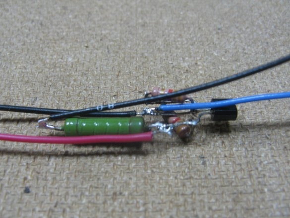
You can power a multimeter from the output of the power board, but I will power it through a separate stabilizer. I will collect it on TL431. You can calculate the output voltage on the calculator.
I fasten the output wires to the adjustment plate. I took the output wires from the old PSU, they already had lugs. I screw to the terminals. I bring out wires with connectors to a multimeter. Glue stabilizer with glue gun. In parallel to the voltage regulation resistor, a 27kΩ resistor was soldered. It seemed to me that the adjustment became smoother.
I almost forgot about the wiring of the toggle switch. I connect both input wires through the toggle switch. I will not install the network connector. Constantly losing the detachable wire, set the wire to constant.
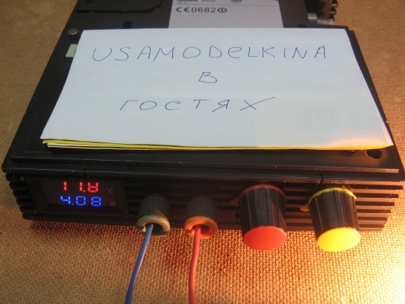
I install a multimeter, twist the case. It was possible to squeeze more than 5A from the block, but this is the limit and not for long. About 4A gives out stably.
A significant minus, judging by the description of such blocks, is the large ripple at the output. I currently do not have an oscilloscope, I will study this issue later. There are plenty of options for reducing ripple on the Internet.
I got such a power supply. Apparently it is noticeable that the block is assembled upside down. The lid of the case is its bottom. The following photo answers this question.
Assembly video available:


