
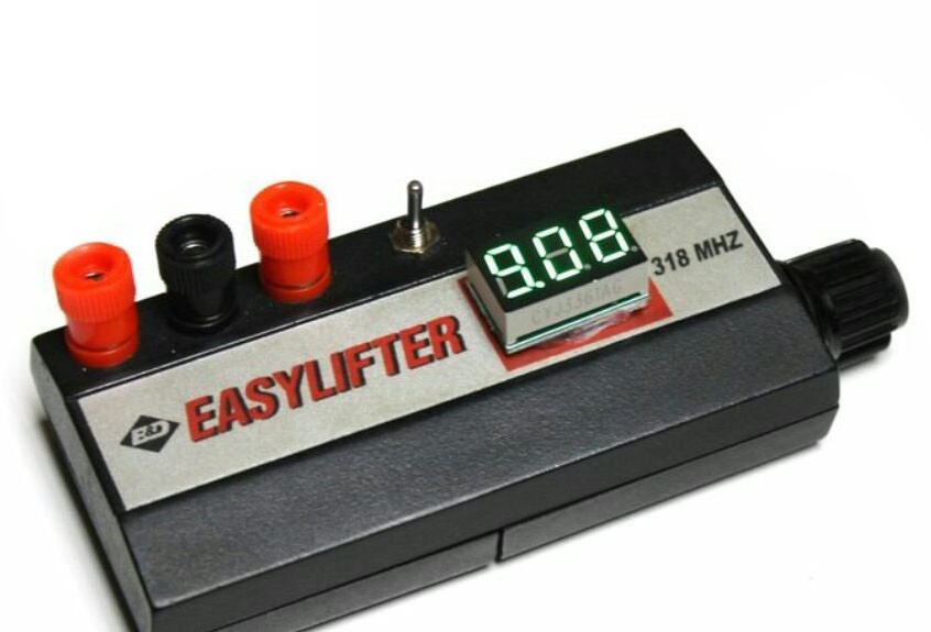
Although there are ways to power circuits on operational amplifiers with unipolar voltage, a bipolar power supply gives better results. You can immediately make a bipolar power supply, or, as the author of Instructables did under the nickname lonesoulsurfer, you can make a prefix to an existing power supply or battery that turns the source into a bipolar. Housing for homemade taken from Easylifter garage door remote control unit.
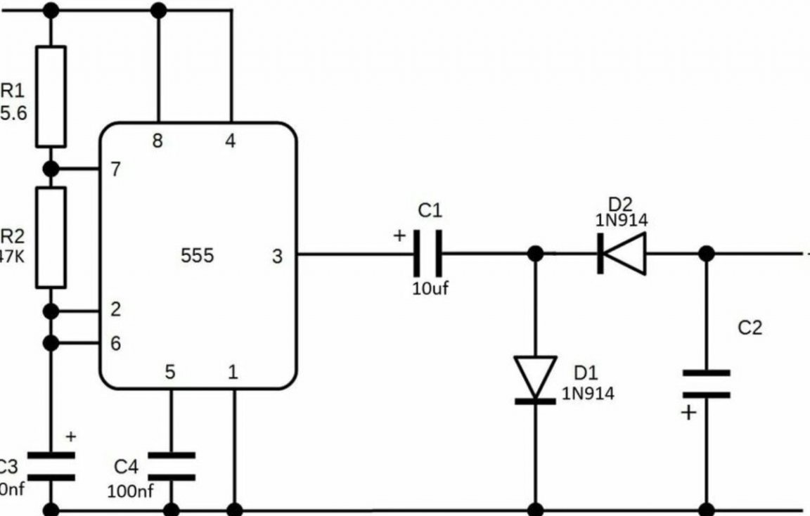
The master took the scheme, proposed by the author of the site All about circuits Robin Mitchell. The device consists of a generator and a rectifier with doubling, turned on so that the voltage at its output is negative, despite the fact that the generator is powered by a positive voltage.
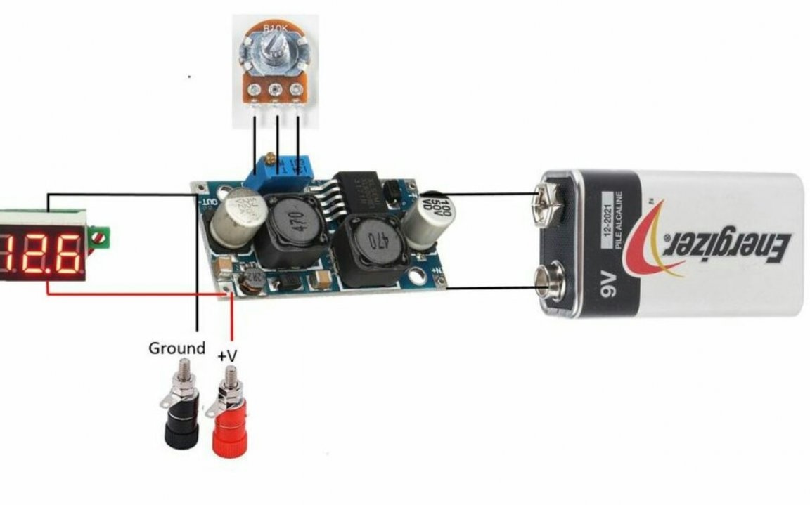
In practice, this circuit will be fed through a ready-made switching regulator, as shown below. The button is needed to discharge the capacitor after reducing the input voltage, otherwise, until this capacitor is discharged through an external circuit, the negative voltage will exceed the positive.
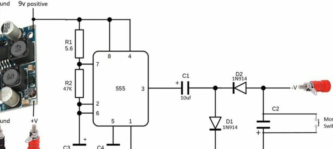
Attention, the error in this scheme. The source of negative voltage should receive power not before, but after the pulse stabilizer. Then, when adjusting the voltage on the converter, both voltages will change: both positive and negative.
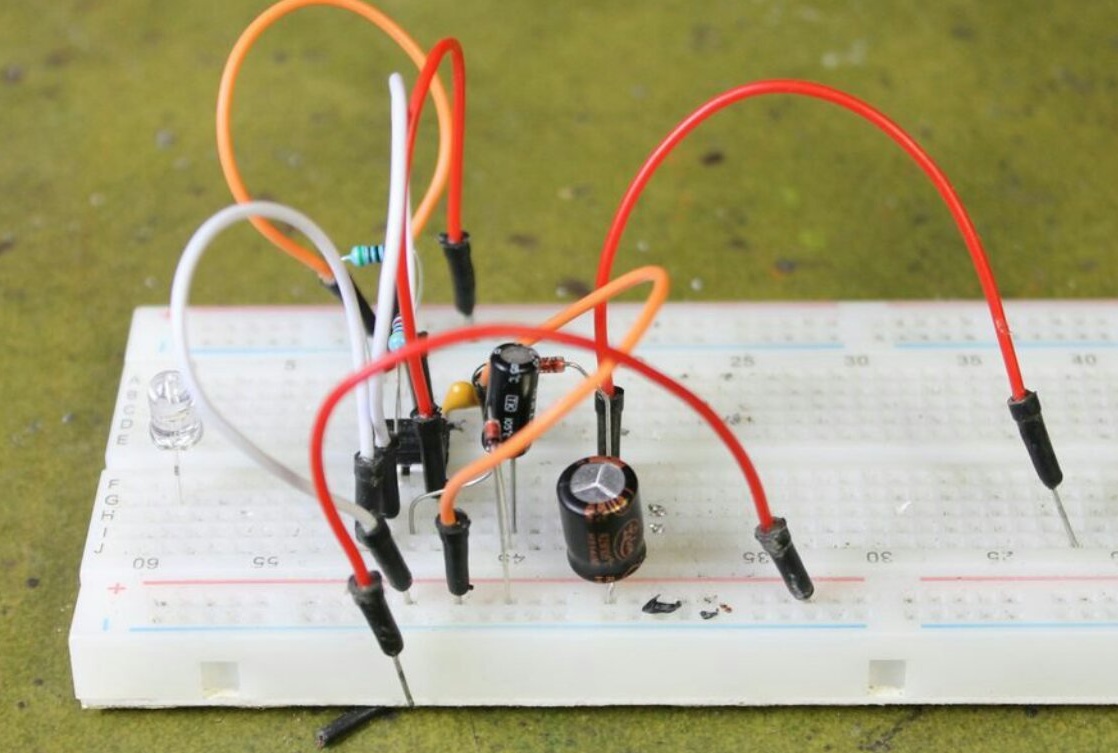
The master tests the source of negative voltage on a breadboard type breadboard and checks in action.

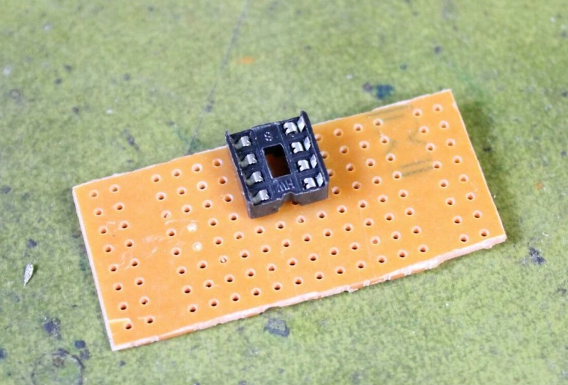
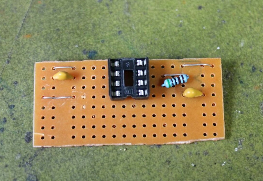
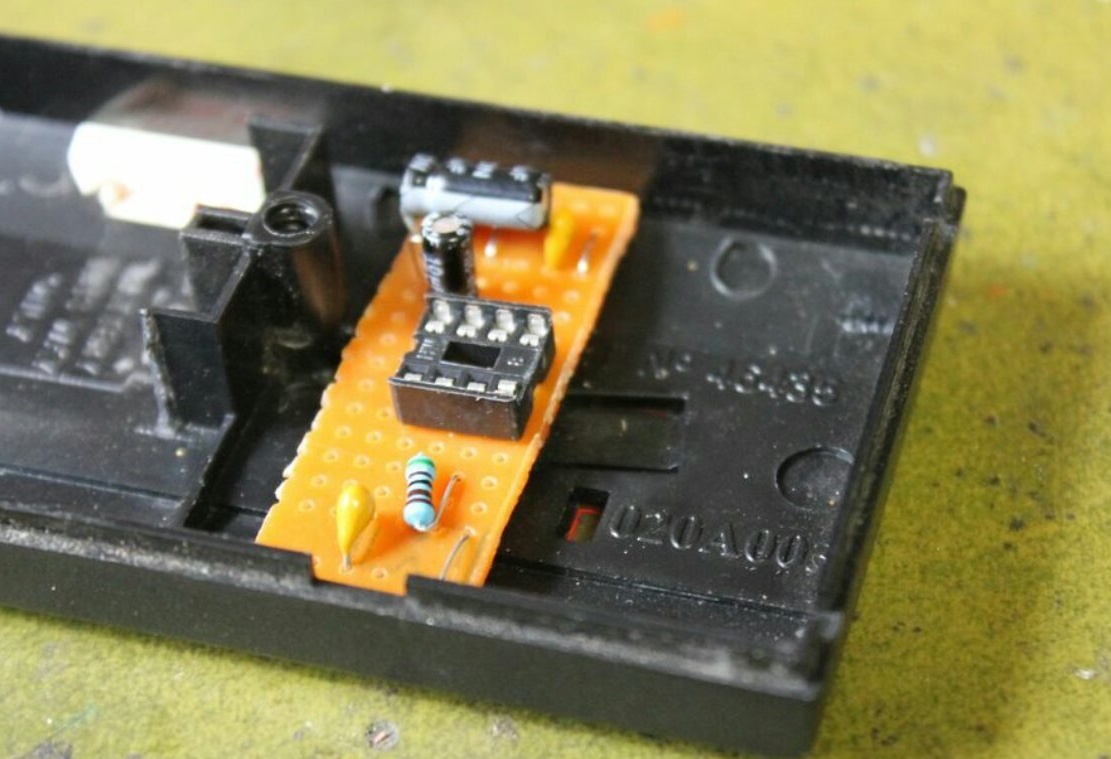
But such a board is bulky; it will not fit in the case chosen by the author. Therefore, he takes a piece of a breadboard of another type - perfboard. Installs a socket for a microcircuit on it (optional if you know how to solder well):
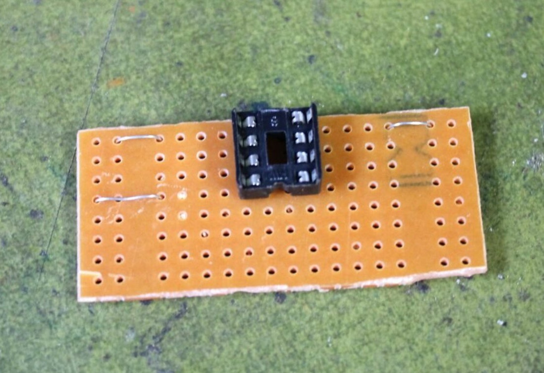
Jumpers:
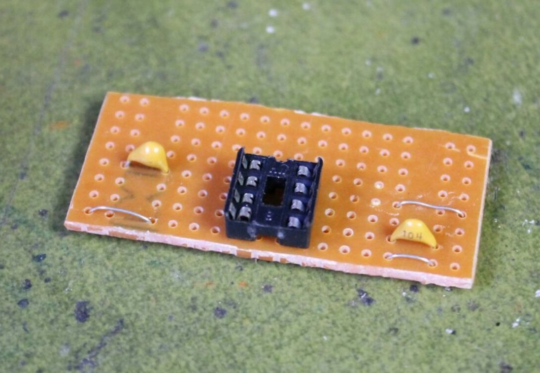
Ceramic Capacitors:
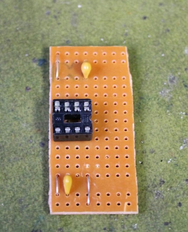
Back side resistor to save board space:
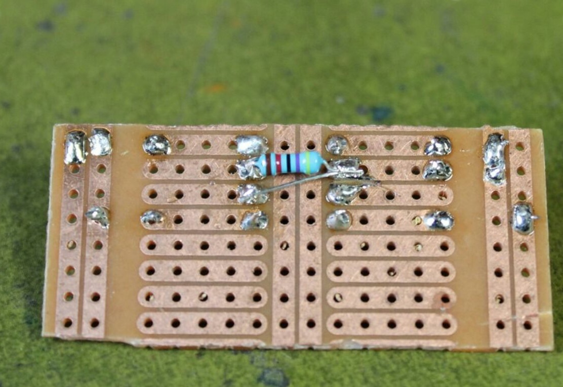
And one more - with the front:
Diode and electrolytic capacitor (these are polar components):
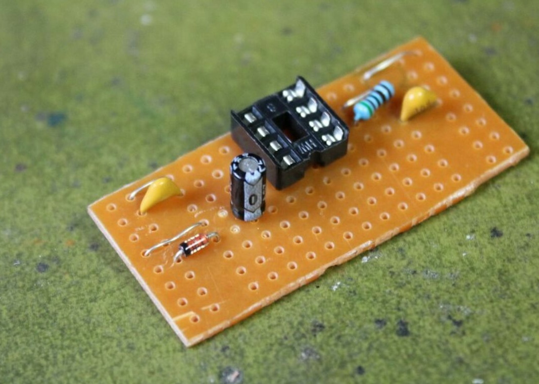
Another diode:

Another electrolytic capacitor:

Long jumpers:
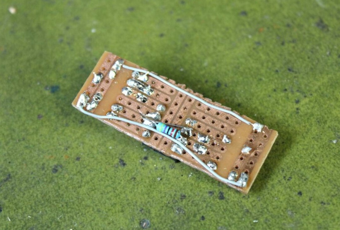
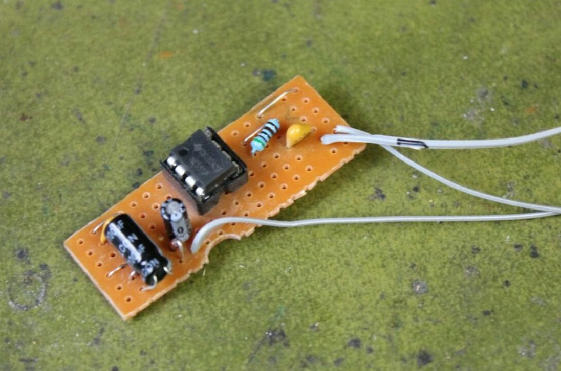
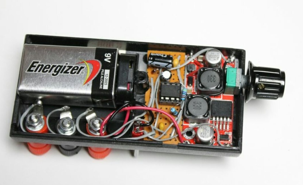
Having collected the board, the master makes sure that it is placed in the case:
Solders conductors to it and again checks in action:
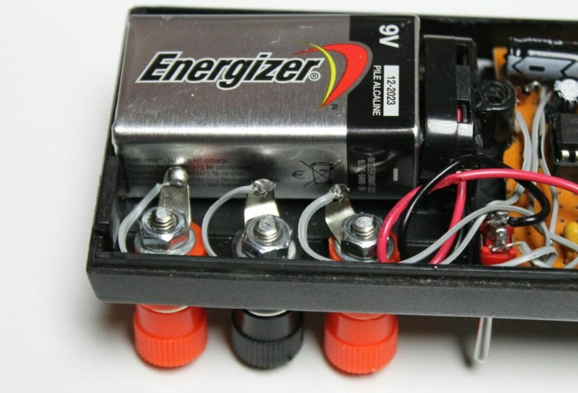
Installs battery, power switch, terminals:

Connects them.It is impossible to abut the terminal petal in the battery as shown in the following photo:
The master connects the voltmeter module:
And replaces the tuning resistor in the pulse stabilizer with a variable:

He squeezes it all very tightly into the case:
Installs a voltmeter and a button on the front panel:
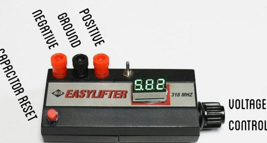
It connects a multimeter operating in a voltmeter mode to a positive output, makes sure that when adjusting the output voltage its readings change synchronously with the readings of the built-in voltmeter. Then he switches the multimeter to the negative output, makes sure that when adjusting upwards, the negative voltage increases synchronously with the positive. When adjusting downwards, this does not happen, the negative voltage becomes equal (modulo) to positive after the discharge of the capacitor with the button.