Homemade, developed by Instructables author under the nickname brianpxbd, automatically controls the brightness of the backlight of the alarm clock depending on the ambient lighting.
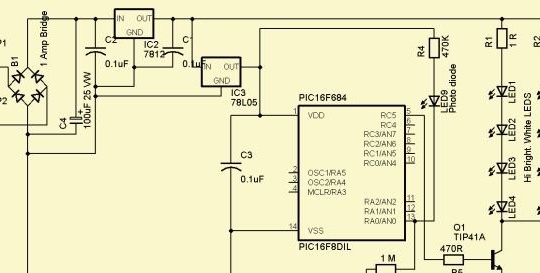
The device is powered by a secondary winding of a step-down transformer with an output voltage of 15 to 18 V (not shown in the diagram). After the rectifier with a filter, two linear stabilizers are installed, one of which provides a voltage of 12 V for powering the LEDs, and the second a voltage of 5 V for powering the microcontroller.

The light sensor is a photodiode, which, unlike a photoresistor, does not contain cadmium. When the light does not enter the photodiode, the corresponding output of the microcontroller turns out to be a 1 MΩ resistor pulled down. The microcontroller generates a PWM signal for controlling the brightness of the LEDs supplied to the transistor switch. The key loads are two chains of LEDs.
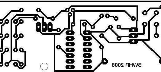
The master designs and manufactures a circuit board for the assembly of the device. Files uploads here: scheme, pay. After downloading, the first file must be changed to SCH, the second to BRD. It is possible to assemble the circuit on a protboard type board as well, for convenience, you can focus on the location of the conductors in the circuit board illustration.

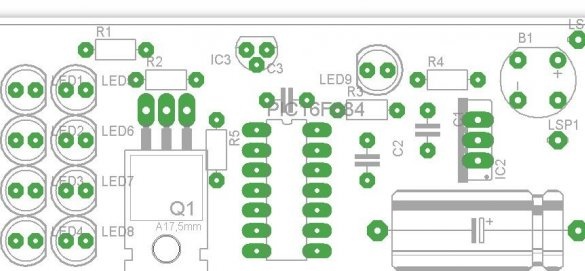
As well as the location of the components on it.
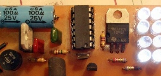
The wizard develops the firmware of the microcontroller and uploads it here. After downloading, the file extension must be changed to HEX. Is not Arduino - To program the microcontroller, you need a homemade or ready-made programmer. After filling in the firmware, the wizard installs the microcontroller and other components on the board.

The master puts the tube on the photodiode so that light from the LEDs does not get on it. It is advisable to install a heat sink on a 12 V voltage regulator. On a transistor operating in key mode, it is not needed.
By applying power to the board from the secondary winding of the aforementioned step-down transformer, the master is convinced of the reaction of the LEDs to a change in the illumination of the photodiode.After making sure that everything works, he installs the board in the alarm case, thereby obtaining a convenient alarm clock with automatic backlight.

The alarm itself continues to be powered by the AA element, but you can add another stabilizer to the design for a voltage of 1.6 - 1.9 V, then it will not need battery power.

