» Topics » Advice »B.A. for OS IN EXCESS OF

B.A. for OS IN EXCESS OF


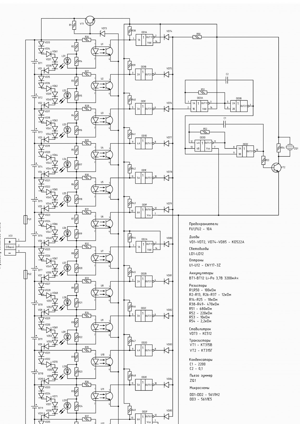
Good day and health to all the inhabitants of our sites. In the last three publications, about perfect lighting in the house, I kind of clearly described how the lighting system works and provided schematic diagrams of the main unit and regulators. And today I represent the finished development. Battery pack for TOP lighting system. Everyone understands that when there is no light in the house, this brings minor inconvenience. Under these circumstances, we begin to hastily look for flashlights, matches, candles, and even worse, get nervous and angry if we are in the bathroom. To prevent such a nervousness, during the development of the system I envisaged feeding it from an independent source. And so I came up with a circuit and created a battery pack.

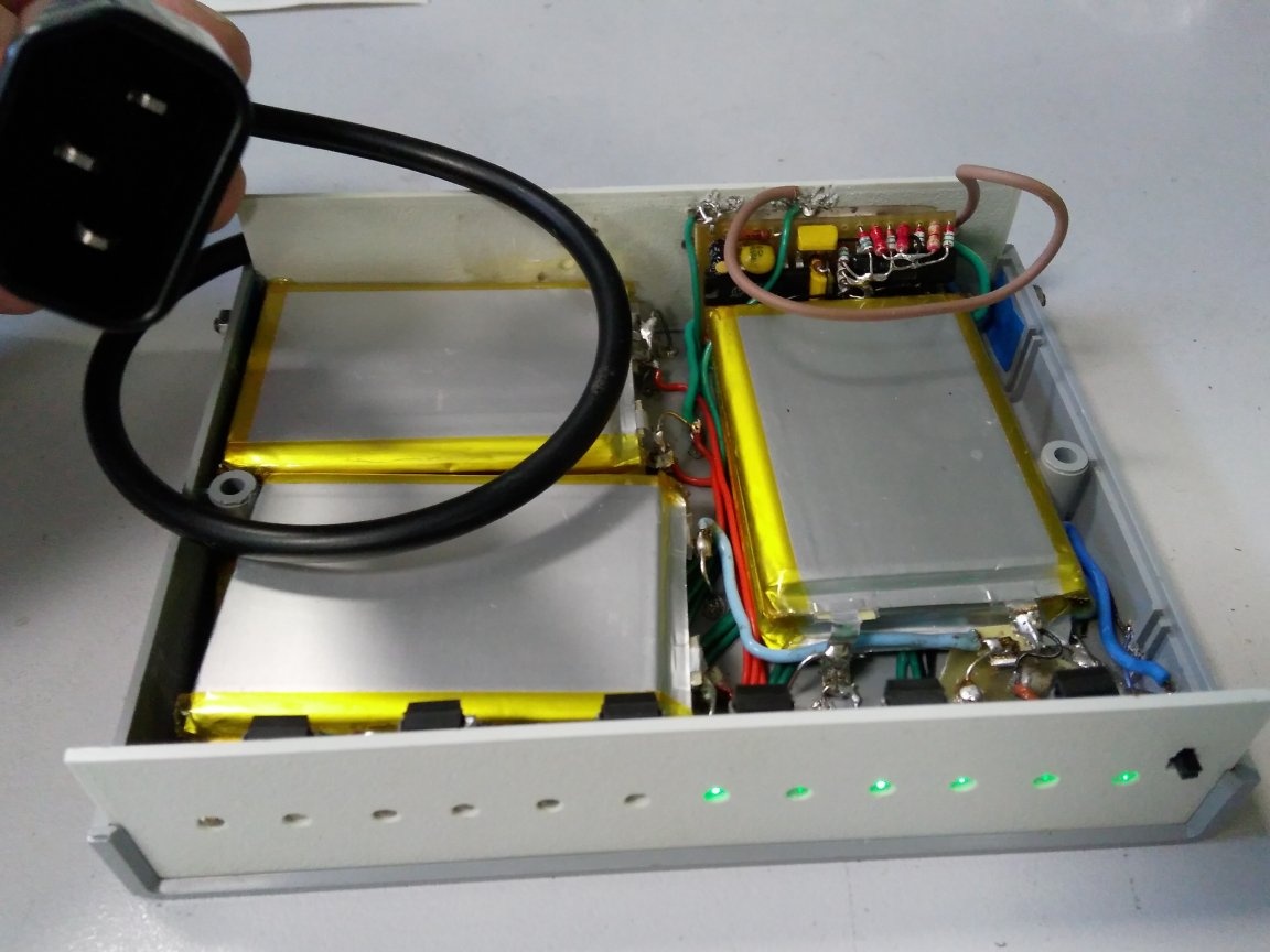
I bought the block case and all accessories in the Chip and Dip store. I mounted LEDs, optocouplers, a switch, resistors on the front panel of the case. All this is established by soldering a rounded conductor into plastic. The photo shows this mounting option.

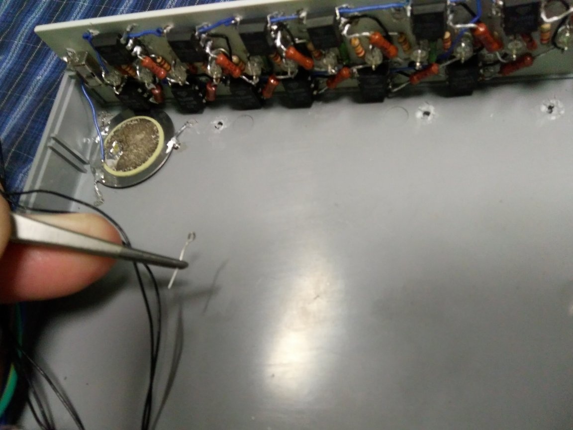
Then he soldered the thin conductors according to the circuit diagram. All that could and should have been connected, without batteries, I unsoldered. Further, using sealant glue, I glued the first six batteries and unsoldered the circuit. I want to emphasize that the soldering circuit with voltage from the battery cells must be very carefully and without rush.

The following six batteries also stuck and neatly soldered the remainder of the circuit.

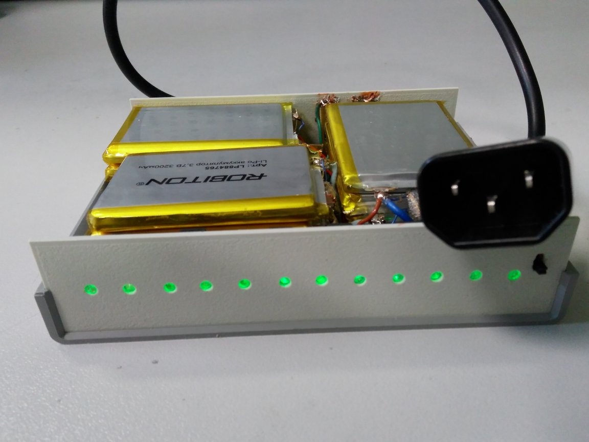
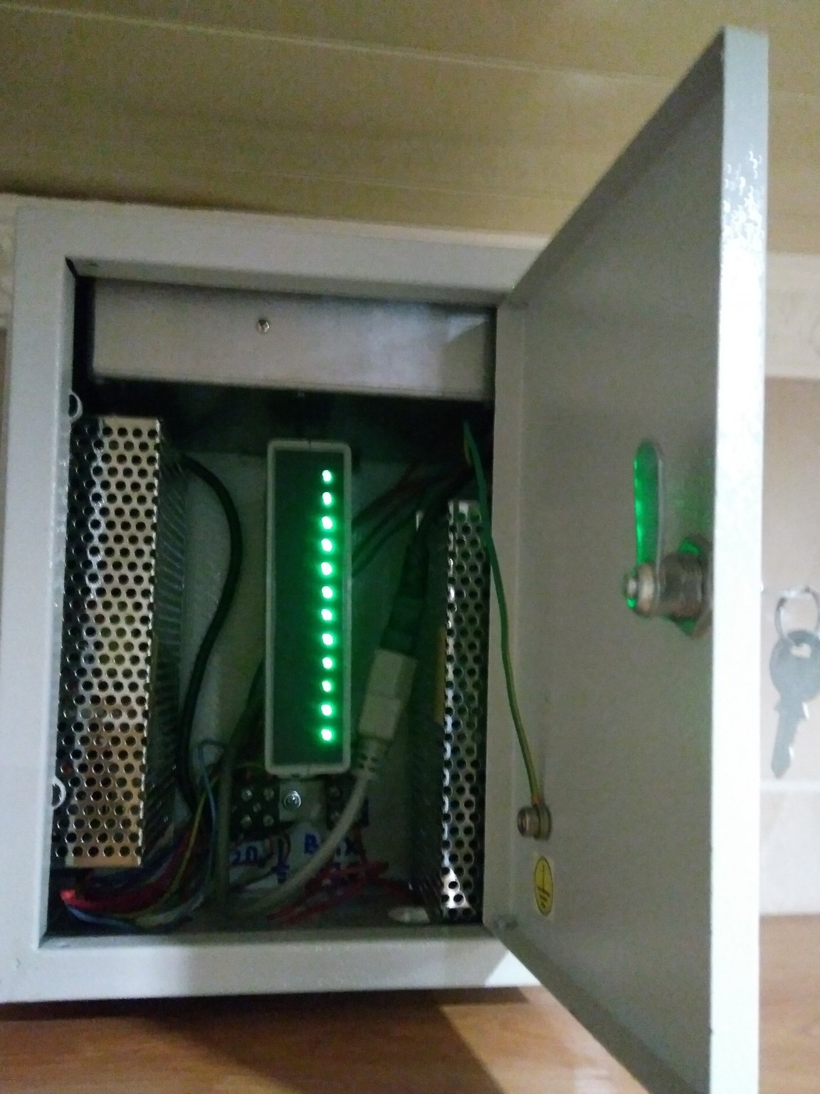
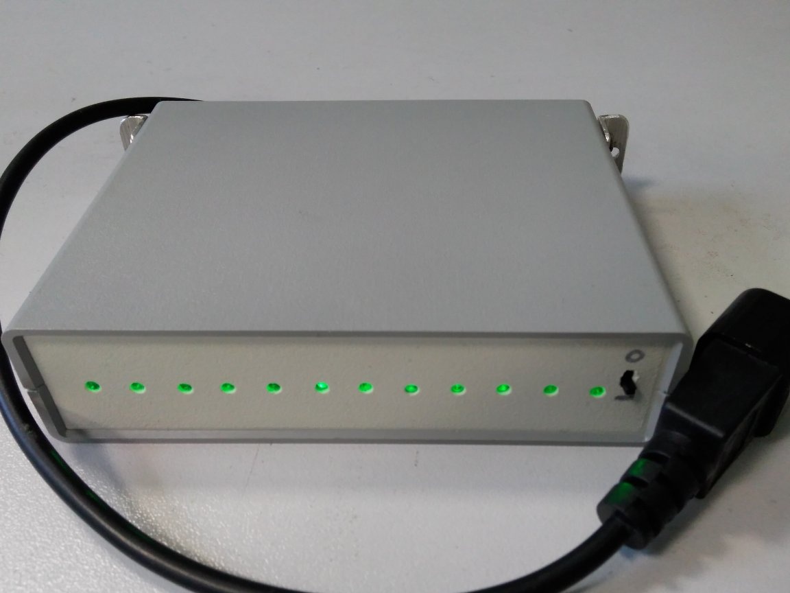
The block is mounted in a box on two aluminum corners. They are screwed to the block body, after its final assembly. This is how it looks like an assembly.

Now it remains to fix the unit in the system box and enjoy the perfect lighting in the house.

Suitable for topic

Related topics

Add a comment

    • smilesmilesxaxaokdontknowyahoonea
      bossscratchfoolyesyes-yesaggressivesecret
      sorrydancedance2dance3pardonhelpdrinks
      stopfriendsgoodgoodgoodwhistleswoontongue
      smokeclappingcraydeclarederisivedon-t_mentiondownload
      heatirefullaugh1mdameetingmoskingnegative
      not_ipopcornpunishreadscarescaressearch
      tauntthank_youthisto_clueumnikacuteagree
      badbeeeblack_eyeblum3blushboastboredom
      censoredpleasantrysecret2threatenvictoryyusun_bespectacled
      shokrespektlolprevedwelcomekrutoyya_za
      ya_dobryihelperne_huliganne_othodifludbanclose
40 comments
Author
Ivan_Pokhmelev,
I agree, everything is correct goodgood Hastily soldered a little scheme and it works. False operation occurs when the batteries sink to a voltage of 3.2 volts, in my scheme it is 2.3 volts. But your option is simpler and I like it more ...
Thank you very much goodgood
Quote: Razrabotchik
with a slight change in the voltage on the batteries, a false positive will occur.

Not at all. The power supply of the IC goes through the stabilizer, the power is approximately 11 V. The typical residual voltage on the FE of the optocouplers is 0.25 V (since there are a lot of optocouples, you can focus on the typical, and not the maximum value of 0.4 V). 0.25 V x 12 = 3 V. The upper resistor in this circuit is not needed at all. Switching voltage IS = 11 V / 2 = 5.5 V. The voltage at its input with all open optocouplers = 11 V - 3 V = 8 V. There is more than enough reserve. If you are completely confused by the maximum residual, you can split it into two parallel chains, turning them on through diodes.
Author
Ivan_Pokhmelev,
All the secrets are familiar to me, and I think it’s clear to you that with a series connection of 12 optocouplers, the total resistance between the collector and the emitter will increase sharply and with a slight change in the voltage on the batteries, a false positive will occur.
An interesting method is to blur obvious stupidity under a catchy heading, snapping a few comments at comments, add another one in case of a decline in interest, etc. , almost to ... whistle Example - https://enm.imdmyself.com/16867-sverh-jekonomija-na-jelektrichestve-s-idealnym-osvescheniem-v-dome.html#comment
We must take into service. xaxa
Quote: Razrabotchik
and there is a fuse from overdischarge

I'm in touch ... mosking
Razrabotchik, in secret, I’ll tell you how 11 more resistors and 11 diodes can be thrown out of my circuit. ;)
You just need to connect the outputs of the optocouplers in series, leaving one resistor and one diode.

Only all of this - backups caused by the initially wrong choice of battery type.
Razrabotchik,
that truth is born with a soldering iron
Looking where to insert! xaxa
For protection against overheating, it is unnecessary here ... There can be no overcharge due to the rated stabilized current, but there is a fuse from overdischarge
One gets the impression that you do not represent in very detail the processes occurring in chemical current sources, especially in Li-Ion ones ... About the ability to think, this is for you on other sites ...
Author
Ivan_Pokhmelev,
I’m reading your thoughts, it’s kind of right and you understand the logic, but there is still a practice that should not be forgotten. I have already argued that with a soldering iron truth is born and all the subtleties are comprehended in the process of practical research. And the simulator in this case does not pull. Here's an example of a piece of the logic circuit that you drew. By logic and theory, everything seems to be okay, but in practice, a connection with an unstable level of units during a power drawdown, which gives false positives for the circuit. To protect against overheating, it is unnecessary here. Batteries overheat from overcharge and overdischarge. The overcharge cannot be due to the rated stabilized current, but there is a fuse against overdischarge. If the battery itself is defective, then an indication circuit and a buzzer will show goodgood
Quote: 2Dem
the idiotic scheme does not provide any protection at all,

I wrote about this in the comments to the previous article, as well as about, to put it mildly, the stupid choice of the battery type. ;)
Quote: Razrabotchik
Everything is warm working

Good excuse, I'll take to practice, the first really useful words from you.
Quote: Razrabotchik
And in what place in the laptop is the protection, I completely disassembled my own and did not find a fig?

Inside the battery there is a circuit, most often on a programmable li-ion battery charging chip, which provides protection against overcharge, overdischarge, temperature and current protection, as well as controlling the disconnection or replacement of cans, while calculating the battery capacity and transmitting this value to the laptop.
Quote: Ivan_Pokhmelev
But here is a new ambush, they have a maximum forward current of 100 mA, and the charger gives 0.6 A.

This is not the most ambush. If you read the technical documentation (for particularly smart datasheets, I do not like this word), it turns out that at a current of 5mA, the voltage drop on these diodes is 0.6-0.7 volts and then it is unstable and depends on several variables, but at a current of 100mA the voltage drop will be already 1 volt and since the idiotic circuit does not provide any protection at all, a fire is guaranteed. That is, the scheme is not just moronic, it is still harmful and dangerous.
Quote: Razrabotchik
I think that at space bases, if ever they will, apply the same scheme

If there are morons who, in their sick imagination, think of using such an idiotic scheme, then there is no need to talk about any bases. You need to drive such mediocrity as you from electricians with sticks.
Author
Ivan_Pokhmelev,
Likely defective caught, forgot to program the counter, this happens with manufacturers. scratch
Quote: Razrabotchik
When the warranty period for batteries expires, the controller blocks the circuit and the charge of the cells stops.
Some passion. ((I have a netbook for 9 years, I have already re-soldered some of the batteries, but it still does not block.;)
Razrabotchik,
I think everyone has already disassembled the battery compartment
You are right, I sorted it out, and not a dozen, and you have not met a single one without a temperature sensor and a circuit for disconnecting the power circuit when the specified temperature is exceeded!
Voltage ratings were within tolerances, but no charge occurred ...
There is a fairly serious protection scheme, in addition to the fuse, the controller can block the battery when the voltage unbalance of any of the cans, with an increased (reduced) charge current - discharge of any of the cans, when the temperature is exceeded, and much more. And it is not always unlocked when normal parameters are reached, more often it locks forever!
Nobody is going to kill anyone
The Criminal Code has a section on manslaughter! I do not know if this case can be attributed to them. yes
Guys, I may not have completely sobered up, but why .....
Author
Ivan_Pokhmelev,
The zener diode does not play the role of a stabilizer, it limits the voltage at the base of the transistor, and taking into account the power supply of the buzzer circuit, the transistor has a margin, but with the electrolyte I didn’t draw it correctly on the circuit, but it costs in the board clapping

Korolev,
Nobody is going to kill anyone. In the laptop battery there is a scarf with a soldered controller and wiring to the batteries. When the warranty period for batteries expires, the controller blocks the circuit and the charge of the cells stops. I think everyone has already disassembled the battery compartment and took measurements on the elements. Voltage ratings were within tolerances, but no charge occurred ... yes-yes
Quote: Razrabotchik
if someone offended by something.

Goodbye boy!
Author
Ivan_PokhmelevYes, the scheme can be considered. In this case, the value of the resistor R50 must be increased by 20 times, and when the voltage is lowered on the battery, an unstable state is created on the optocoupler collector which can trigger the buzzer. The circuit is basically correct, but I do not like unstable states and therefore I put an inverter into the circuit. dance3 I am very glad that you are all interested ... thanks for your participation and I'm sorry if I offended someone with something.
Razrabotchik,
In my practice, points are either measuring control points or a jumper field
But only? And in my practice I came across the notation given by ino53
By the way, the minimum stabilization current KS512A is 1 mA. You have the sum of the zener current and the base of the transistor less than 0.4 mA.
The voltage drop at the collector-emitter junction VT1 is close to the maximum allowable, there is almost no margin, and given the spread of the stabilization voltage of the zener diode and lower voltage at low current, there is no margin at all.
There is no capacitor at the output of the stabilizer.
Guys, why do we need glasses for him? Let's chat, or ....
Razrabotchik,
And in what place in the laptop is protection
We read carefully:
in the battery of laptops
For those in the tank: Battery is the abbreviation for Rechargeable Battery!
I completely disassembled my own and did not find a fig?
xaxa The laptop does not need to be disassembled, but it is necessary to know that Li-Ion and Li-Po banks are prone to swelling and fire. You can kill people!
Quote: Razrabotchik
Draw your options and I will prove that you are wrong.

Quote: pogranec
ino53,
how to draw a diagram.
those. if several radio components of the same and with the same nominal value go sequentially in the circuit, then the beginning and end of the circuit are plotted, and between them are the points by the number of components?
ESKD read
Sorry, I don’t remember the details
Author
pogranec,
In my practice, the points are either measurement control points or a field for jumpers. I don’t know how to draw or draw now negative
ino53,
how to draw a diagram.
those. if several radio components of the same and with the same nominal value go sequentially in the circuit, then the beginning and end of the circuit are plotted, and between them are the points by the number of components?
Author
And in what place in the laptop is the protection, I completely disassembled my own and did not find a fig? pardon
Razrabotchik,
Thermal protection from what? Everything is warm working and within normal limits
Yes, here I think, what for in the laptop battery (and not only) they put protection against overheating? scratch
Author
Korolev,
Thermal protection from what? Everything is warmly working and within normal limits. And in case of a fire in an apartment or house, everything will go to hell.

ino53,
Well, yes, I also drew something in a draft sketch (in dashed lines), but in the complete diagram I decided to fit it into grinding ... victory
ino53,
From overdischarge - and is not provided, but from overcharge - it is said above
I will add the core too. Thermal protection not provided? In a closed box, in a locked drawer, possibly in the closed back of the cottage ... Burn, burn, clearly ... xaxa
Now the boy from the former circle went in to congratulate (the boy is decent for 30), and drew how to draw a diagram.
Quote: Ivan_Pokhmelev
And this too, but not only. LN2 is superfluous here: we remove them, we reverse the diodes, put the right leg of R50 on a common one, change LE5 to LA7 - the functioning does not change.
Well, sir, you are threatened with the principle of the product, down! xaxa

Quote: Ivan_Pokhmelev
in the main unit, a current stabilizer circuit and it takes into account the charge time. How is this?)))
Well, an interesting question ...
Quote: Ivan_Pokhmelev
Where will the current flow when the battery is charging?
600 mA through 100 mA diodes, i.e. ... matyukov down!
Author
Ivan_Pokhmelev,
All legs where they should be and without LN2 can not do, you need to read the diagram correctly. Draw your options and I will prove that you are wrong. derisive The charging time for this circuit is one carriage and a small trolley, because I am not a supporter of the fast charge of batteries and this is taken into account in the circuit. And when the batteries are charged, only 10 milliamps of current flows through the entire diode chain.
Quote: ino53
only the 9th leg seemed to get lost.
And this too, but not only.LN2 is superfluous here: we remove them, we reverse the diodes, put the right leg of R50 on a common one, change LE5 to LA7 - the functioning does not change.

Quote: Razrabotchik
in the main unit is a current stabilizer circuit and it takes into account the charge time.
This is how?)))

Quote: Razrabotchik
Six diodes connected in parallel to each element provide a voltage balance during the series connection of the batteries and the main current does not flow through their transition.

Where will the current flow when the battery is charging?
Author
ino53,
Thank you, all the guys also congratulate you on the holiday! dance3 The charge and discharge level of each battery element is shown by a parallel connected through a divider LED. It goes out at a voltage of 3.3 and burns brightly at 4.0. As for the optocouplers, they control the short circuit of the batteries and form a control signal for the buzzer. And the buzzer provides sound control of the malfunction when the drawer door is closed. As for recharging, it simply cannot be, since the main unit has a current stabilizer circuit and it takes into account the charge time. And at overdischarge, if it’s K.Z. the fuse will save. And the total current value, when the network is disconnected with the maximum power consumption of the lighting lamps and fixtures, changes with decreasing voltage on the batteries and all these values ​​are not critical for B.A. circuit Six diodes connected in parallel to each element provide a voltage balance during the series connection of the batteries and the main current does not flow through their transition. Something like this... sorry
Quote: Ivan_Pokhmelev
Okay, let's say this is a mistake for the designer of the circuit and there is KD522A. But here is a new ambush, they have a maximum forward current of 100 mA, and the charger gives 0.6 A. ((
I wanted to find the CVC of this diode for the post. current, but I saw this figure - 100 mA, and changed my mind.
Quote: Ivan_Pokhmelev
I will not repeat that the circuit does not protect the batteries from either overcharging or overdischarge. ((
From overdischarge - and is not provided, but from overcharge - it is said above.
Quote: Ivan_Pokhmelev
It is strange to determine the battery level using an optocoupler due to low accuracy.
There was such a class of devices, they had an “I” stamp on the glass - indicator (?), Without accuracy class. And so - yes, in the whole scheme there is not a single supporting element.
Quote: Ivan_Pokhmelev
And the sound alarm scheme is generally extremely strange. ((
No, it’s a typical intermittent signal (pee-pee), only the 9th leg seems to be lost. And generally speaking


Yes, happy holiday, men!
B.A. for OS IN EXCESS OF
Just a super-name, in comparison with which all the mistakes in the names that were before are simply masterpieces of the accuracy of the description.
Now to the circuit.
In the list of components (it’s impossible to name this list, of course) some mysterious diodes KABOUT522A:

Okay, let's say this is a mistake for the designer of the circuit and there is KD522A. But here is a new ambush, they have a maximum forward current of 100 mA, and the charger gives 0.6 A. ((
I will not repeat that the circuit does not protect the batteries from either overcharging or overdischarge. ((
It is strange to determine the battery level using an optocoupler due to low accuracy.
And the sound alarm scheme is generally extremely strange. ((
Author
ino53,
Well, yes, if I, in a schematic diagram, because of an old man’s carelessness, forgot to draw a piezo buzzer switch, on the space station everyone will go crazy because of the accident B.A. and jump into outer space help And now a little more serious. At space stations, the on-board voltage is from 27 to 34 volts. Solar batteries charge the main battery pack, then through the fuse box the voltage is distributed to all consumers. Therefore, for example, to connect a laptop, you need an appropriate converter.In my version of OS, if it is used on the ISS, it is also necessary to replace two power supplies (220/24) with converters (27-34 / 24). I think that at space bases, if ever they will, apply the same scheme. But we probably won’t live up to this point and all issues, at best, our grandchildren will decide, and at worst, invaders are aliens. sun_bespectacled
N-yes, it was good for you to work there with space (if this is true) - he threw his dope into orbit, and who the hell will figure it out, whose fault it shied away. We had it differently - a training ground, night, rain, dirt and blood under the tracks, guys with weapons nearby, and you know what they will write about you - the designer died during the test of the product ...

latest comments

All comments

We advise you to read:

Hand it for the smartphone ...