

If you suddenly need an LED matrix of a non-standard size or shape, then you can always assemble it with your own hands. We will consider the manufacture of a matrix of ultraviolet diodes, while creating a kind of money authenticity detector. This will allow you to verify the authenticity of the currency purchased from friends or on the street and be sure that you are not deceived.
In this video, we suggest you watch the process of creating such an LED matrix.
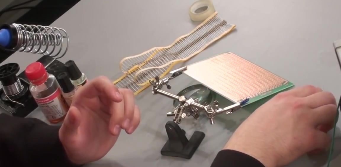
For work, we need to prepare the following:
- bread board;
- 100 LEDs;
- soldering iron;
- 100 resistors;
- adhesive tape;
- nippers;
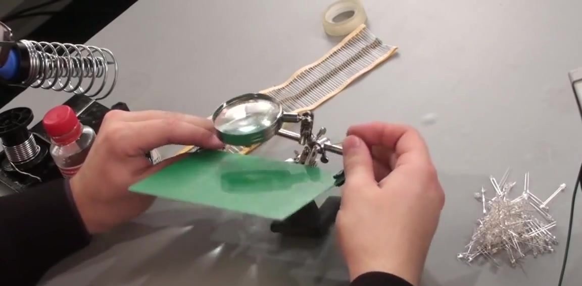
Having prepared everything you need, we proceed to the manufacture of LED matrix with dimensions of 100x100 mm.
To power the LEDs, we will use a voltage of 5 V, we use resistors with a nominal value of 470 Ohms, this is necessary to set the desired current value of 20 mA passing through each LED.
To simplify the task of creating an LED matrix as much as possible, we will connect all the LEDs in parallel. However, with such a connection, it is very important to remember that each LED must have its own current-limiting resistor.
First, solder the LEDs on the board. For convenience, we fix each line consisting of them with tape so that we have the opportunity to turn the board over and solder the entire line of LEDs at once.
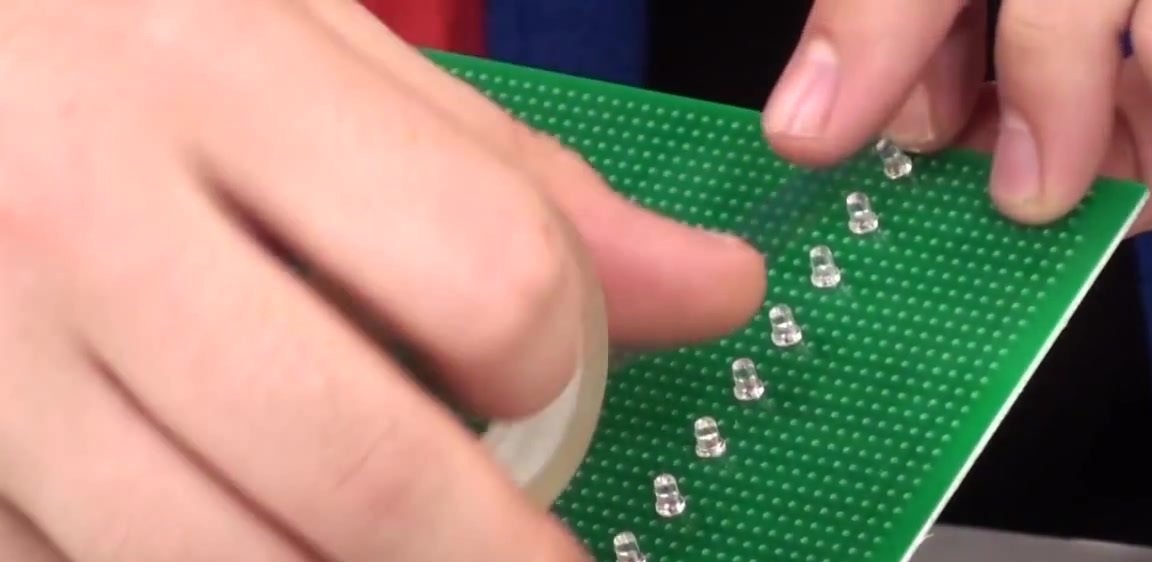
We arrange all the LEDs on the board. Please note that these radio elements have anode and cathode leads. In order not to make a mistake, the longer output has a “+” sign. We fix them with tape to temporarily fix them in place.
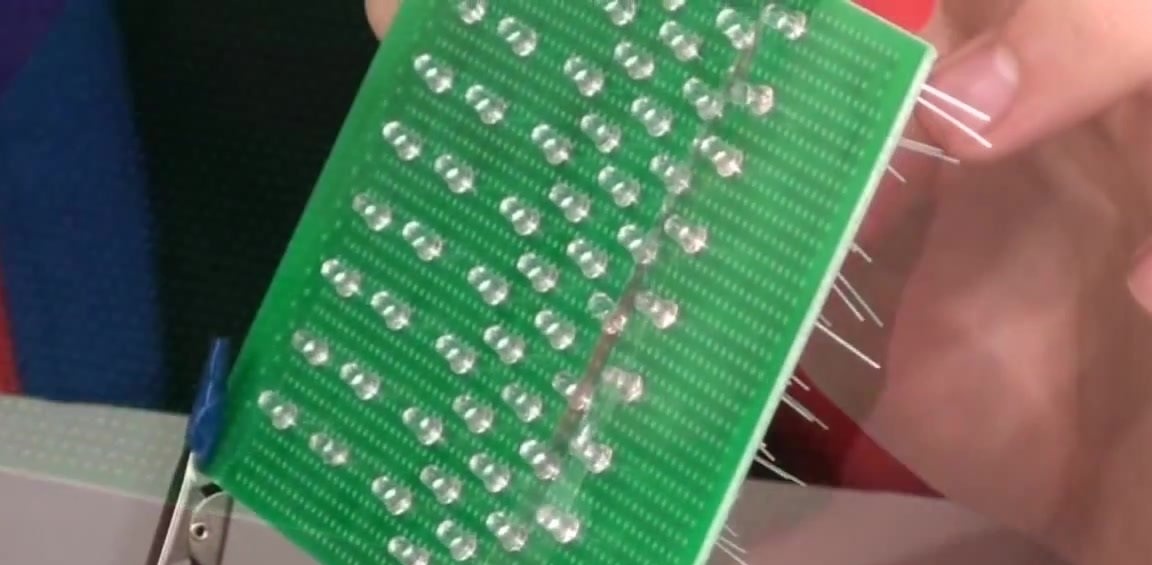
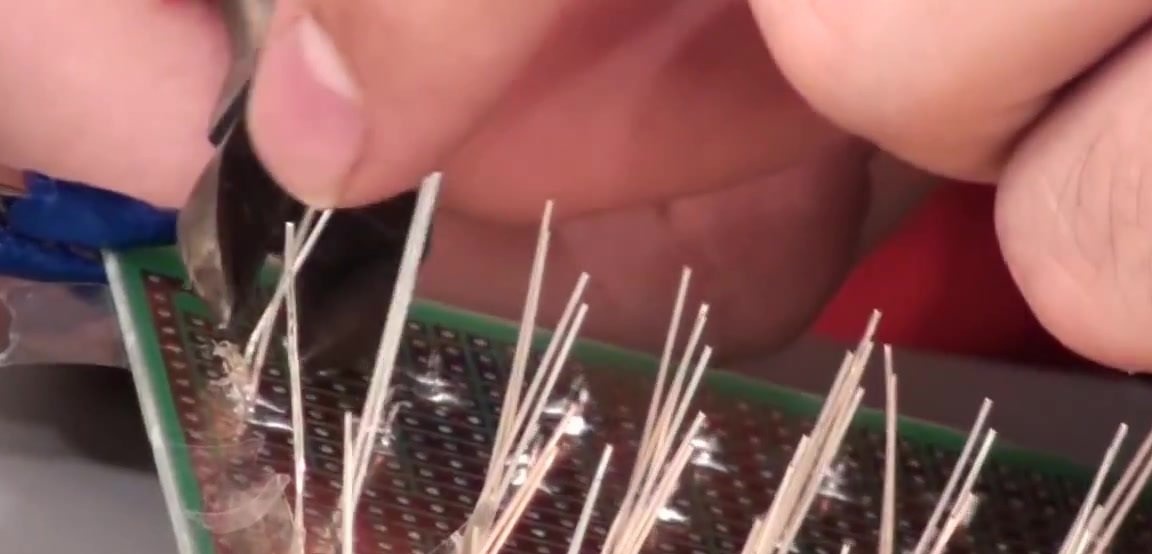
Now we turn over our board, on the reverse side of which there are the conclusions of all the LEDs and we begin to slowly solder them one after another.
After soldering the first row, so that the conclusions of the soldered LEDs do not interfere with further work, you can bite with the help of nippers. We remove the tape.
After all the LEDs are soldered, their conclusions are bitten off, we begin to arrange the resistors. They do not have polarities, so it does not matter which side to put them on.
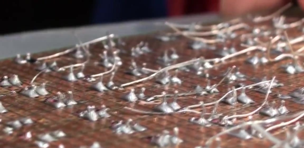
We solder all the resistors, also biting off the extra length of the leads.
The soldering of the board is finished, now we supply power to it and check that all the LEDs are on.
It remains only to install the finished board in the case and get the finished device.